EP0473182A2 - Appareil de formation d'images - Google Patents
Appareil de formation d'images Download PDFInfo
- Publication number
- EP0473182A2 EP0473182A2 EP91114612A EP91114612A EP0473182A2 EP 0473182 A2 EP0473182 A2 EP 0473182A2 EP 91114612 A EP91114612 A EP 91114612A EP 91114612 A EP91114612 A EP 91114612A EP 0473182 A2 EP0473182 A2 EP 0473182A2
- Authority
- EP
- European Patent Office
- Prior art keywords
- driving force
- image forming
- forming apparatus
- transmitting means
- force transmitting
- Prior art date
- Legal status (The legal status is an assumption and is not a legal conclusion. Google has not performed a legal analysis and makes no representation as to the accuracy of the status listed.)
- Granted
Links
- 238000000034 method Methods 0.000 claims abstract description 38
- 230000005540 biological transmission Effects 0.000 claims abstract description 20
- 230000007246 mechanism Effects 0.000 claims description 39
- 230000000903 blocking effect Effects 0.000 claims 4
- 238000010276 construction Methods 0.000 description 1
- 230000003287 optical effect Effects 0.000 description 1
- 230000002093 peripheral effect Effects 0.000 description 1
Images





Classifications
-
- G—PHYSICS
- G03—PHOTOGRAPHY; CINEMATOGRAPHY; ANALOGOUS TECHNIQUES USING WAVES OTHER THAN OPTICAL WAVES; ELECTROGRAPHY; HOLOGRAPHY
- G03G—ELECTROGRAPHY; ELECTROPHOTOGRAPHY; MAGNETOGRAPHY
- G03G15/00—Apparatus for electrographic processes using a charge pattern
-
- G—PHYSICS
- G03—PHOTOGRAPHY; CINEMATOGRAPHY; ANALOGOUS TECHNIQUES USING WAVES OTHER THAN OPTICAL WAVES; ELECTROGRAPHY; HOLOGRAPHY
- G03G—ELECTROGRAPHY; ELECTROPHOTOGRAPHY; MAGNETOGRAPHY
- G03G21/00—Arrangements not provided for by groups G03G13/00 - G03G19/00, e.g. cleaning, elimination of residual charge
- G03G21/16—Mechanical means for facilitating the maintenance of the apparatus, e.g. modular arrangements
- G03G21/18—Mechanical means for facilitating the maintenance of the apparatus, e.g. modular arrangements using a processing cartridge, whereby the process cartridge comprises at least two image processing means in a single unit
- G03G21/1803—Arrangements or disposition of the complete process cartridge or parts thereof
- G03G21/1807—Arrangements or disposition of the complete process cartridge or parts thereof colour
-
- G—PHYSICS
- G03—PHOTOGRAPHY; CINEMATOGRAPHY; ANALOGOUS TECHNIQUES USING WAVES OTHER THAN OPTICAL WAVES; ELECTROGRAPHY; HOLOGRAPHY
- G03G—ELECTROGRAPHY; ELECTROPHOTOGRAPHY; MAGNETOGRAPHY
- G03G15/00—Apparatus for electrographic processes using a charge pattern
- G03G15/01—Apparatus for electrographic processes using a charge pattern for producing multicoloured copies
-
- G—PHYSICS
- G03—PHOTOGRAPHY; CINEMATOGRAPHY; ANALOGOUS TECHNIQUES USING WAVES OTHER THAN OPTICAL WAVES; ELECTROGRAPHY; HOLOGRAPHY
- G03G—ELECTROGRAPHY; ELECTROPHOTOGRAPHY; MAGNETOGRAPHY
- G03G15/00—Apparatus for electrographic processes using a charge pattern
- G03G15/01—Apparatus for electrographic processes using a charge pattern for producing multicoloured copies
- G03G15/0105—Details of unit
- G03G15/0126—Details of unit using a solid developer
-
- G—PHYSICS
- G03—PHOTOGRAPHY; CINEMATOGRAPHY; ANALOGOUS TECHNIQUES USING WAVES OTHER THAN OPTICAL WAVES; ELECTROGRAPHY; HOLOGRAPHY
- G03G—ELECTROGRAPHY; ELECTROPHOTOGRAPHY; MAGNETOGRAPHY
- G03G15/00—Apparatus for electrographic processes using a charge pattern
- G03G15/06—Apparatus for electrographic processes using a charge pattern for developing
- G03G15/08—Apparatus for electrographic processes using a charge pattern for developing using a solid developer, e.g. powder developer
- G03G15/0896—Arrangements or disposition of the complete developer unit or parts thereof not provided for by groups G03G15/08 - G03G15/0894
-
- G—PHYSICS
- G03—PHOTOGRAPHY; CINEMATOGRAPHY; ANALOGOUS TECHNIQUES USING WAVES OTHER THAN OPTICAL WAVES; ELECTROGRAPHY; HOLOGRAPHY
- G03G—ELECTROGRAPHY; ELECTROPHOTOGRAPHY; MAGNETOGRAPHY
- G03G21/00—Arrangements not provided for by groups G03G13/00 - G03G19/00, e.g. cleaning, elimination of residual charge
- G03G21/16—Mechanical means for facilitating the maintenance of the apparatus, e.g. modular arrangements
- G03G21/1604—Arrangement or disposition of the entire apparatus
- G03G21/1623—Means to access the interior of the apparatus
- G03G21/1628—Clamshell type
-
- G—PHYSICS
- G03—PHOTOGRAPHY; CINEMATOGRAPHY; ANALOGOUS TECHNIQUES USING WAVES OTHER THAN OPTICAL WAVES; ELECTROGRAPHY; HOLOGRAPHY
- G03G—ELECTROGRAPHY; ELECTROPHOTOGRAPHY; MAGNETOGRAPHY
- G03G21/00—Arrangements not provided for by groups G03G13/00 - G03G19/00, e.g. cleaning, elimination of residual charge
- G03G21/16—Mechanical means for facilitating the maintenance of the apparatus, e.g. modular arrangements
- G03G21/1642—Mechanical means for facilitating the maintenance of the apparatus, e.g. modular arrangements for connecting the different parts of the apparatus
- G03G21/1647—Mechanical connection means
-
- G—PHYSICS
- G03—PHOTOGRAPHY; CINEMATOGRAPHY; ANALOGOUS TECHNIQUES USING WAVES OTHER THAN OPTICAL WAVES; ELECTROGRAPHY; HOLOGRAPHY
- G03G—ELECTROGRAPHY; ELECTROPHOTOGRAPHY; MAGNETOGRAPHY
- G03G21/00—Arrangements not provided for by groups G03G13/00 - G03G19/00, e.g. cleaning, elimination of residual charge
- G03G21/16—Mechanical means for facilitating the maintenance of the apparatus, e.g. modular arrangements
- G03G21/18—Mechanical means for facilitating the maintenance of the apparatus, e.g. modular arrangements using a processing cartridge, whereby the process cartridge comprises at least two image processing means in a single unit
- G03G21/1839—Means for handling the process cartridge in the apparatus body
- G03G21/1857—Means for handling the process cartridge in the apparatus body for transmitting mechanical drive power to the process cartridge, drive mechanisms, gears, couplings, braking mechanisms
-
- G—PHYSICS
- G03—PHOTOGRAPHY; CINEMATOGRAPHY; ANALOGOUS TECHNIQUES USING WAVES OTHER THAN OPTICAL WAVES; ELECTROGRAPHY; HOLOGRAPHY
- G03G—ELECTROGRAPHY; ELECTROPHOTOGRAPHY; MAGNETOGRAPHY
- G03G2221/00—Processes not provided for by group G03G2215/00, e.g. cleaning or residual charge elimination
- G03G2221/16—Mechanical means for facilitating the maintenance of the apparatus, e.g. modular arrangements and complete machine concepts
- G03G2221/1603—Mechanical means for facilitating the maintenance of the apparatus, e.g. modular arrangements and complete machine concepts for multicoloured copies
-
- G—PHYSICS
- G03—PHOTOGRAPHY; CINEMATOGRAPHY; ANALOGOUS TECHNIQUES USING WAVES OTHER THAN OPTICAL WAVES; ELECTROGRAPHY; HOLOGRAPHY
- G03G—ELECTROGRAPHY; ELECTROPHOTOGRAPHY; MAGNETOGRAPHY
- G03G2221/00—Processes not provided for by group G03G2215/00, e.g. cleaning or residual charge elimination
- G03G2221/16—Mechanical means for facilitating the maintenance of the apparatus, e.g. modular arrangements and complete machine concepts
- G03G2221/1651—Mechanical means for facilitating the maintenance of the apparatus, e.g. modular arrangements and complete machine concepts for connecting the different parts
- G03G2221/1654—Locks and means for positioning or alignment
-
- G—PHYSICS
- G03—PHOTOGRAPHY; CINEMATOGRAPHY; ANALOGOUS TECHNIQUES USING WAVES OTHER THAN OPTICAL WAVES; ELECTROGRAPHY; HOLOGRAPHY
- G03G—ELECTROGRAPHY; ELECTROPHOTOGRAPHY; MAGNETOGRAPHY
- G03G2221/00—Processes not provided for by group G03G2215/00, e.g. cleaning or residual charge elimination
- G03G2221/16—Mechanical means for facilitating the maintenance of the apparatus, e.g. modular arrangements and complete machine concepts
- G03G2221/1651—Mechanical means for facilitating the maintenance of the apparatus, e.g. modular arrangements and complete machine concepts for connecting the different parts
- G03G2221/1657—Mechanical means for facilitating the maintenance of the apparatus, e.g. modular arrangements and complete machine concepts for connecting the different parts transmitting mechanical drive power
-
- G—PHYSICS
- G03—PHOTOGRAPHY; CINEMATOGRAPHY; ANALOGOUS TECHNIQUES USING WAVES OTHER THAN OPTICAL WAVES; ELECTROGRAPHY; HOLOGRAPHY
- G03G—ELECTROGRAPHY; ELECTROPHOTOGRAPHY; MAGNETOGRAPHY
- G03G2221/00—Processes not provided for by group G03G2215/00, e.g. cleaning or residual charge elimination
- G03G2221/16—Mechanical means for facilitating the maintenance of the apparatus, e.g. modular arrangements and complete machine concepts
- G03G2221/18—Cartridge systems
- G03G2221/183—Process cartridge
- G03G2221/1853—Process cartridge having a submodular arrangement
Definitions
- the present invention relates to an electrophotography, and more particularly it relates to a process cartridge having a plurality of developing means for developing a latent image formed on an electrophotographic photosensitive member, and an image forming apparatus using such cartridge.
- each developing unit comprises a developing roller for applying developer (toner) to the photosensitive member, and a container for containing the developer.
- the present invention aims to eliminate the above-mentioned conventional drawbacks, and has an object to provide a process cartridge and an image forming apparatus, which can facilitate the mounting and dismounting of the cartridge without the engagement and disengagement of a connection mechanism during the mounting and dismounting operation of the cartridge and which are simple and inexpensive.
- the present invention provides a process cartridge adapted to integrally support an electrophotographic photosensitive member and a plurality of developing means and removable with respect to a body of an image forming apparatus, and comprising a first driving force transmitting means for receiving a driving force from the image forming apparatus to drive the photosensitive member; developer supplying means provided in the respective developing means and adapted to supply developer to the photosensitive member; second driving force transmitting means provided in the respective developing means to drive the developer supplying means; and a third driving force transmitting means disposed between the first and second driving force transmitting means and adapted to selectively transmit a driving force from the first driving force transmitting means to any one of the developing means.
- the present invention also provides an image forming apparatus on which the above-mentioned process cartridge can be mounted.
- Fig. 1 is an elevational view of a main portion of an image forming apparatus
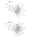
- Figs. 2 and 3 are views for explaining an operation of a driving force transmitting mechanism associated to the present invention
- Fig. 4 is an elevational sectional view of the image forming apparatus.
- a cartridge 2 including a plurality of developing units 3 therein can be removably mounted on a body of an image forming apparatus 1.
- the image forming apparatus as shown is embodied as a printer which exposes an electrophotographic photosensitive drum A with a laser beam from an optical scanning means B.
- the cartridge 2 is constituted by the photosensitive drum A, a charger roller C for uniformly charging the drum, a cleaner D for removing the residual toner from the drum, and a frame E for integrally supporting these elements.
- a transfer drum F is disposed at a position opposing to the cartridge 2, which transfer drum receives a transfer sheet from a sheet supply cassette P and holds the transfer sheet during the multi-transfer process.
- a transfer corona discharger G is fixedly disposed within the transfer drum F, which discharger provides a transfer bias for transferring toner images formed on the photosensitive drum onto the transfer sheet sequentially. After the transfer process, the transfer sheet is separated from the transfer drum F and is fed to a fixing heat roller H, where the image is fixed to the sheet. Then, the sheet is ejected onto an ejection tray I.
- the developing units 3 comprise an yellow developing units 3a for yellow toner, a magenta developing unit 3b for magenta toner, a cyan developing unit 3c for cyan toner, and a black developing unit 3d for black toner.
- a full-color image can be formed on the transfer sheet by repeating the development of a latent image with each color and the transferring of the developed image onto the sheet.
- the cartridge 2 can be inserted into the image forming apparatus along guide and support rails 20.
- a driving force is transmitted from a driving source (motor) 4 disposed within the image forming apparatus 1 to a gear 6 at an apparatus side via a belt 5, and further to gears 10 of the developing units 3 via gears 7, 8, 9 disposed at a cartridge side (Fig. 2).
- the gears 8 and 9 are mounted on plates 11, and each plate 11 can be pivoted around an axis of the gear 8 so that the gear 9 is biased to be meshed with the corresponding gear 10.
- the belt 5 and the gears 6, 7, 8 constitute a driving force transmitting mechanism at the apparatus side
- the gears 10 constitute a driving force transmitting mechanism for rotating sleeves in the developing units 3.
- a circular cam 12 is disposed in coaxial with the gear 7 and is provided at its peripheral portion with a notch 12a.
- the cam 12, gears 9 and plates 11 constitute a changing mechanism for controlling ON/OFF of the connection between the driving force transmitting mechanism at the apparatus side and the driving force transmitting mechanism at the developing unit side.
- the cam 12 When the cartridge 2 is mounted and dismounted with respect to the image forming apparatus, the cam 12 is in a condition shown in Fig. 2. In this condition, ends of all of the plates 11 are abutted against the profile of the cam 12 other than the notch 12a, with the result that all of the gears 9 are disengaged from the respective gears 10. Accordingly, in this condition, since the connections of driving force transmitting paths between the developing units 3 of the cartridge 2 and the driving source 4 in the image forming apparatus 1 are released, the cartridge 2 can easily be mounted on or dismounted from the image forming apparatus 1. Incidentally, other than the image forming operation, if the condition shown in Fig. 2 is maintained, it is not needed to release the connection of the driving force transmitting paths each time when the cartridge is mounted on or dismounted from the apparatus.
- the developing units 3 are selectively driven in a manner described hereinbelow. That is to say, when the cam 12 is rotated as shown in Fig. 3, the plate 11 engaged by the notch 12a of the cam is rotated in a clockwise direction in Fig. 3 around the corresponding gear 8 by a biasing force of a spring (not shown), with the result that only the gear 9 mounted on this plate 11 is engaged by the corresponding gear 10, thus driving the developing unit 3 having this gear 10. Accordingly, the changing mechanism constituted by the gears 9, plates 11 and cam 12 has also a function for selecting the driving force to any developing unit 3. Consequently, any changing mechanism independently provided in the conventional apparatus can be omitted, thus simplifying the driving force transmitting mechanism and making the apparatus inexpensive.
- the cam 12 is rotatingly driven by a driving source (not shown), and the drive of the cam is controlled in response to the developing unit 3 to be driven and the condition of the mounting and dismounting of the cartridge 2 so that the cam is stopped at a predetermined angular position.
- Fig. 5 is an elevational view of an image forming apparatus
- Fig. 6 is a side view of a driving force transmitting mechanism
- Figs. 7A and 8A are elevational views of a cam
- Figs. 7B and 8B are views looked at from a direction shown by the arrow X in Fig. 6,
- Figs. 9A and 9B are perspective views of the cam.
- a driving force is transmitted from a driving source (motor) 4 to a gear 6 disposed at an apparatus side via a belt 5, and further to gears 10 of developing units 3 via gears 13, 14 disposed at a cartridge side.
- the gears 14 are biased toward a cam 15 by means of corresponding springs 18.
- the cam 15 having a recess 15a is rotated and the recess 15a is stopped at a position shown in Fig. 8A, as shown in Fig. 8B, the gear 14 is shifted into the recess 15a by means of the biasing force of the corresponding spring 18 so that the gear 14 is meshed with the corresponding gear 10, thus transmitting the driving force to this gear 10.
- the recess 15a of the cam 15 is stopped at a position shown in Fig. 7A, as shown in Fig. 7B, any gear 14 cannot enter into the recess 15a, thus preventing the engagement between the gear 14 and the corresponding gear 10.
- the driving force to the developing units can be selected by rotating the cam 15, the driving force transmitting mechanism can be simplified, thus achieving the cost-down, similar to the previous embodiment.
- the cam 15 is rotatingly driven by a driving source 17 (Fig. 6) via a gear 16.
- a driving force transmitting device which is arranged in an image forming apparatus wherein a cartridge including a plurality of developing units can be removably mounted within the apparatus and which selectively transmits a driving force to one of the developing units
- the driving force transmitting device including a connection mechanism for controlling ON/OFF of the connection between a driving force transmitting mechanism disposed at a developing unit side and a driving force transmitting mechanism disposed at an apparatus side and being characterized in that the connection mechanism serves to turn OFF the connection between the driving force transmitting mechanisms other than the image forming process and has a function for selecting the driving force transmission to the developing units. Consequently, it is not needed to perform the engagement and disengagement of the connection mechanism during the mounting and dismounting of the cartridge, thus facilitating the mounting and dismounting operations of the cartridge and achieving the cost-down.
- the black toner developing unit 3d may be of cartridge type, other than the other developing units 3a - 3c, in order to afford it to a larger capacity, since the black toner is more frequently used than the other toners.
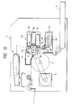
- Figs. 10 and 11 are elevational sectional view of a multi-color image forming apparatus.
- a main cartridge 2a at a photosensitive drum side and an auxiliary cartridge 21 at a black toner developing unit side are removable with respect to the image forming apparatus 1.
- the main cartridge 2a includes therein a photosensitive drum A, a charging corona discharger Ca, and a plurality of developing units 3a - 3c for yellow, magenta and cyan toners, respectively; and the auxiliary cartridge 21 comprises a single developing unit for black toner.
- a driving source 4 disposed within the image forming apparatus 1 serves to transmits a driving force to a gear 6 disposed within the image forming apparatus 1.
- the gear 6 is positioned in coaxial with the photosensitive drum A in the cartridge 2a when the latter is mounted within the image forming apparatus.
- the main cartridge 2a includes drive gears 14, 22.
- the gear 14 serve to transmit driving forces to sleeves (developer bearing members) 23 of the developing units 3a - 3c, respectively, via gears 10; whereas, the gear 22 serves to transmit a driving force to a sleeve 24 of the auxiliary cartridge 21, via a gear 25.
- the gears 14, 22 can selectively drive the sleeves 22, 24.
- the auxiliary cartridge 21 since the transmission of the driving force to the auxiliary cartridge 21 is effected via the main cartridge 2a, the auxiliary cartridge 21 may merely be positioned only with respect to the main cartridge 2a. As a result, the positioning accuracy of the sleeve 24 of the auxiliary cartridge 21 regarding the photosensitive drum A of the main cartridge 2a is improved, and the mounting and dismounting mechanism for the auxiliary cartridge 21 is simplified, thus improving the operability. Further, a drive connecting mechanism for connecting the gear 6 at the apparatus side and the main cartridge 2a is also simplified.
- the developing units 3a - 3c in the main cartridge 2a have developer agitating members 26, respectively, which are intermittently rotated by the driving force to agitate the developer in the units.
- the auxiliary cartridge 21 is also provided with developer agitating members 27 which are rotatingly driven by the driving force from the main cartridge 2a via a gear 28.
- the developer agitating members 27 of the auxiliary cartridge 21 receive the driving force from the sleeve gear 25 via gears 29, 30.
- the connections for the drive can be effected simultaneously.
- FIGs. 14 and 15 A further embodiment is shown in Figs. 14 and 15.
- a gear 31 is disposed in coaxial with the photosensitive drum A in the main cartridge 2a, which gear 31 is meshed with gears 33 for the sleeves 23 of the developing units 3a - 3c.
- these drive gears 33 have electromagnetic clutches (not shown), respectively. By selectively turning the electromagnetic clutches ON/OFF, the developing units 3a - 3c are selectively driven.
- a sleeve drive gear 35 is fixedly mounted on a sleeve shaft of the sleeve 24 of the auxiliary cartridge 21 and has an electromagnetic clutch (not shown).
- the sleeve gear 35 is engaged by the gear 31 of the main cartridge 2a, thus permitting the drive of the auxiliary cartridge 21.
- FIGs. 16 to 18 A still further embodiment is shown in Figs. 16 to 18.
- Figs. 17A and 18A are elevational views of a cam 26, and Figs. 17B and 18B are bottom views of the developing unit changing mechanism (looked at from a direction shown by the arrow Y in Fig. 16).
- the developing unit changing mechanism includes a cam 36 of the same type as that illustrated in Fig. 9, which cam is disposed in coaxial with the photosensitive drum A.
- the cam 36 having a recess 36a operates in the same manner as the aforementioned cam 15.
- One of changing gears 37 arranged at the main cartridge side is selectively engaged by the recess 36a.
- a transmission gear 38 of the auxiliary cartridge 21 is shifted to a position where the transmission gear can be meshed with one of the gears 37. In this condition, when the cam recess 36a is positioned as shown in Fig.
- the changing gear 37 associated with the transmission gear 38 in the previous embodiment is arranged at the auxiliary cartridge side.
- the driving force is transmitted to the transmission gear 38 of the auxiliary cartridge 21. That is to say, similar to the previous embodiment, the driving force of the driving source 4 (Fig. 19) is transmitted to the transmission gear 38 via the gears 6, 13 and 37, thus driving the auxiliary cartridge 21.
- a drive mechanism used with an image forming apparatus wherein a main cartridge including at least a photosensitive member and developing units and an auxiliary cartridge including at least one developing unit are removable with respect to a body of the image forming apparatus, and having a driving source arranged at an apparatus side and adapted to drive the main cartridge and the auxiliary cartridge, the mechanism is characterized in that the drive connection is effected between the image forming apparatus and the main cartridge and the drive transmission to the auxiliary cartridge is effected via the main cartridge.
- drive force exerted from the gear 7 can be utilized to rotate also the drum A adding to drive the gears 8 of developing devices.
- a process cartridge integrally supporting an electrophotographic photosensitive member and a plurality of developing means and removable with respect to an image forming apparatus The driving force from the image forming apparatus can be selectively transmitted to any one of the developing means and the transmission of the driving force to all of the developing means is blocked during the non-image forming process.
- the operability of dismounting of the cartridge from the image forming apparatus is improved.
Landscapes
- Physics & Mathematics (AREA)
- General Physics & Mathematics (AREA)
- Engineering & Computer Science (AREA)
- Computer Vision & Pattern Recognition (AREA)
- Color Electrophotography (AREA)
- Dry Development In Electrophotography (AREA)
- Electrophotography Configuration And Component (AREA)
Applications Claiming Priority (4)
| Application Number | Priority Date | Filing Date | Title |
|---|---|---|---|
| JP22841390 | 1990-08-31 | ||
| JP228413/90 | 1990-08-31 | ||
| JP2257131A JP2672028B2 (ja) | 1990-09-28 | 1990-09-28 | 多色画像形成装置 |
| JP257131/90 | 1990-09-28 |
Publications (3)
| Publication Number | Publication Date |
|---|---|
| EP0473182A2 true EP0473182A2 (fr) | 1992-03-04 |
| EP0473182A3 EP0473182A3 (en) | 1992-03-18 |
| EP0473182B1 EP0473182B1 (fr) | 1996-07-10 |
Family
ID=26528236
Family Applications (1)
| Application Number | Title | Priority Date | Filing Date |
|---|---|---|---|
| EP91114612A Expired - Lifetime EP0473182B1 (fr) | 1990-08-31 | 1991-08-30 | Appareil de formation d'images |
Country Status (4)
| Country | Link |
|---|---|
| US (1) | US5235383A (fr) |
| EP (1) | EP0473182B1 (fr) |
| KR (1) | KR940010127B1 (fr) |
| DE (1) | DE69120746T2 (fr) |
Cited By (3)
| Publication number | Priority date | Publication date | Assignee | Title |
|---|---|---|---|---|
| EP0509726A3 (en) * | 1991-04-15 | 1993-06-30 | Canon Kabushiki Kaisha | Image forming apparatus |
| EP0533484A3 (en) * | 1991-09-20 | 1993-07-07 | Canon Kabushiki Kaisha | An image forming apparatus |
| US5452064A (en) * | 1991-11-22 | 1995-09-19 | Canon Kabushiki Kaisha | Image forming apparatus having a transfer member rotatable in synchronism with a photosensitive member |
Families Citing this family (31)
| Publication number | Priority date | Publication date | Assignee | Title |
|---|---|---|---|---|
| US5471284A (en) * | 1990-01-19 | 1995-11-28 | Canon Kabushiki Kaisha | Image forming apparatus having toner depletion detection feature |
| US5521693A (en) * | 1991-05-14 | 1996-05-28 | Canon Kabushiki Kaisha | Image forming apparatus and process cartridge detachably mountable to same |
| KR950004444B1 (ko) * | 1991-11-25 | 1995-05-01 | 삼성전자주식회사 | 전자사진 방식을 이용한 기기의 동력전달장치 |
| EP0671667A3 (fr) * | 1994-03-11 | 1999-02-03 | Konica Corporation | Appareil électrophotographique de formation d'images en couleur |
| US5420676A (en) * | 1994-07-07 | 1995-05-30 | Hewlett-Packard Company | Electrophotographic printer having cam-operated transfer roller and developer module |
| US5940657A (en) * | 1996-03-05 | 1999-08-17 | Canon Kabushiki Kaisha | Developing cartridge |
| JP3869903B2 (ja) * | 1996-03-05 | 2007-01-17 | キヤノン株式会社 | 電子写真画像形成装置 |
| JP3869902B2 (ja) * | 1996-03-05 | 2007-01-17 | キヤノン株式会社 | 現像カートリッジ及び電子写真画像形成装置 |
| KR100297977B1 (ko) | 1996-04-23 | 2001-10-26 | 모리시타 요이찌 | 칼라전자사진장치 |
| JP3416486B2 (ja) * | 1996-09-30 | 2003-06-16 | キヤノン株式会社 | 現像カートリッジ及び電子写真画像形成装置 |
| AU736223B2 (en) * | 1996-09-30 | 2001-07-26 | Canon Kabushiki Kaisha | Developing device and electrophotographic image forming apparatus |
| JP3566507B2 (ja) * | 1997-08-01 | 2004-09-15 | キヤノン株式会社 | 電子写真画像形成装置 |
| JP3862374B2 (ja) | 1997-09-04 | 2006-12-27 | キヤノン株式会社 | 画像処理装置及び方法 |
| JPH11265135A (ja) | 1998-03-16 | 1999-09-28 | Canon Inc | クリーニング装置、プロセスカートリッジ、電子写真画像形成装置 |
| US6157792A (en) * | 1998-03-31 | 2000-12-05 | Canon Kabushiki Kaisha | Electrophotographic apparatus having plural image forming modes, and a process cartridge applied to such electrophotographic apparatus |
| JP3893222B2 (ja) | 1998-08-31 | 2007-03-14 | キヤノン株式会社 | シャッターピン及び現像カートリッジ |
| JP3554200B2 (ja) * | 1998-08-31 | 2004-08-18 | キヤノン株式会社 | プロセスカートリッジ及び画像形成装置及びクリーニング部材取り付け方法 |
| JP2000075733A (ja) | 1998-08-31 | 2000-03-14 | Canon Inc | 電子写真感光体ドラム取り付け方法、及び、電子写真感光体ドラム交換方法、及び、プロセスカートリッジ |
| JP3768706B2 (ja) | 1998-12-28 | 2006-04-19 | キヤノン株式会社 | 電子写真画像形成装置 |
| JP2000194248A (ja) | 1998-12-28 | 2000-07-14 | Canon Inc | プロセスカ―トリッジ及び帯電ユニット及び現像ユニット |
| JP3679645B2 (ja) | 1999-03-29 | 2005-08-03 | キヤノン株式会社 | プロセスカートリッジ |
| JP3293818B2 (ja) * | 1999-05-20 | 2002-06-17 | キヤノン株式会社 | プロセスカートリッジ及び電子写真画像形成装置 |
| JP3478797B2 (ja) | 1999-12-28 | 2003-12-15 | キヤノン株式会社 | プロセスカートリッジ及び電子写真画像形成装置 |
| JP4250294B2 (ja) | 2000-02-16 | 2009-04-08 | キヤノン株式会社 | カラー電子写真画像形成装置及びプロセスカートリッジ |
| US6493528B2 (en) | 2000-03-03 | 2002-12-10 | Canon Kabushiki Kaisha | Image forming unit and image forming apparatus |
| EP2048546A3 (fr) | 2000-09-01 | 2011-03-16 | Canon Kabushiki Kaisha | Cartouche ayant une ouverture d'alimentation de développeur et appareil de formation d'image utilisable avec celle-ci |
| JP2005186332A (ja) * | 2003-12-24 | 2005-07-14 | Brother Ind Ltd | 画像形成装置 |
| JP4498407B2 (ja) | 2006-12-22 | 2010-07-07 | キヤノン株式会社 | プロセスカートリッジ、電子写真画像形成装置、及び、電子写真感光体ドラムユニット |
| JP5311854B2 (ja) | 2007-03-23 | 2013-10-09 | キヤノン株式会社 | 電子写真画像形成装置、現像装置、及び、カップリング部材 |
| MA46363A (fr) | 2016-09-30 | 2019-08-07 | Canon Kk | Cartouche de toner et mécanisme d'alimentation de toner |
| CN109804318B (zh) | 2016-09-30 | 2021-09-28 | 佳能株式会社 | 调色剂盒和调色剂供应机构 |
Family Cites Families (11)
| Publication number | Priority date | Publication date | Assignee | Title |
|---|---|---|---|---|
| DE3117278C2 (de) * | 1981-04-30 | 1985-10-03 | Siemens AG, 1000 Berlin und 8000 München | Antriebssystem für ein elektrofotografisches nichtmechanisches Druck- oder Kopiergerät |
| JPH0799448B2 (ja) * | 1985-02-27 | 1995-10-25 | 三田工業株式会社 | シエル型静電複写機 |
| JPS62177563A (ja) * | 1986-01-30 | 1987-08-04 | Toshiba Corp | 画像形成装置 |
| JPS63210858A (ja) * | 1987-02-27 | 1988-09-01 | Toshiba Corp | 画像形成装置 |
| US4984026A (en) * | 1988-04-25 | 1991-01-08 | Minolta Camera Kabushiki Kaisha | Color image forming method |
| US5038176A (en) * | 1988-06-07 | 1991-08-06 | Minolta Camera Kabushiki Kaisha | Image forming apparatus having plural magnetic brush developing devices |
| JPH0283574A (ja) * | 1988-09-20 | 1990-03-23 | Seiko Epson Corp | 液晶パネルの実装方法 |
| CA2003398A1 (fr) * | 1988-11-21 | 1990-05-21 | Shizuo Morita | Machine a photocopier en couleurs avec cartouche de traitement amovible |
| JP2627946B2 (ja) * | 1988-11-30 | 1997-07-09 | 三田工業株式会社 | カラー画像生成機 |
| DE68913488D1 (de) * | 1988-12-27 | 1994-04-07 | Konishiroku Photo Ind | Farbbilderzeugungsgerät. |
| JPH037774A (ja) * | 1989-06-05 | 1991-01-14 | Mitsubishi Yuka Badische Co Ltd | 防藻用塗料組成物 |
-
1991
- 1991-08-29 US US07/751,965 patent/US5235383A/en not_active Expired - Fee Related
- 1991-08-30 EP EP91114612A patent/EP0473182B1/fr not_active Expired - Lifetime
- 1991-08-30 DE DE69120746T patent/DE69120746T2/de not_active Expired - Fee Related
- 1991-08-31 KR KR1019910015181A patent/KR940010127B1/ko not_active Expired - Fee Related
Cited By (5)
| Publication number | Priority date | Publication date | Assignee | Title |
|---|---|---|---|---|
| EP0509726A3 (en) * | 1991-04-15 | 1993-06-30 | Canon Kabushiki Kaisha | Image forming apparatus |
| US5495327A (en) * | 1991-04-15 | 1996-02-27 | Canon Kabushiki Kaisha | Image forming apparatus |
| EP0533484A3 (en) * | 1991-09-20 | 1993-07-07 | Canon Kabushiki Kaisha | An image forming apparatus |
| US5323210A (en) * | 1991-09-20 | 1994-06-21 | Canon Kabushiki Kaisha | Image forming apparatus featuring a multiple mode service access main assembly |
| US5452064A (en) * | 1991-11-22 | 1995-09-19 | Canon Kabushiki Kaisha | Image forming apparatus having a transfer member rotatable in synchronism with a photosensitive member |
Also Published As
| Publication number | Publication date |
|---|---|
| US5235383A (en) | 1993-08-10 |
| EP0473182B1 (fr) | 1996-07-10 |
| KR920005001A (ko) | 1992-03-28 |
| KR940010127B1 (ko) | 1994-10-21 |
| DE69120746D1 (de) | 1996-08-14 |
| EP0473182A3 (en) | 1992-03-18 |
| DE69120746T2 (de) | 1996-12-12 |
Similar Documents
| Publication | Publication Date | Title |
|---|---|---|
| US5235383A (en) | Process cartridge and image forming apparatus using same | |
| US9244385B2 (en) | Image forming apparatus that switches positions of developing rollers in a predetermined fixed order | |
| US6795671B2 (en) | Image forming apparatus featuring switchable, contact and spaced, clutch-operated developing units | |
| US4743938A (en) | Color image forming apparatus | |
| US5258819A (en) | Image forming apparatus having a revolver type developing device | |
| EP1970775B1 (fr) | Appareil de formation d'images et son dispositif de transmission d'alimentation | |
| RU2518169C2 (ru) | Технологический картридж и устройство формирования изображений | |
| EP0509726B1 (fr) | Appareil de formation d'images | |
| US6115568A (en) | Image forming apparatus with intermediate transfer member | |
| US11556089B2 (en) | Image forming apparatus | |
| US5325151A (en) | Revolver type developing device for an image forming apparatus | |
| US5669046A (en) | Transmission/coupling device and image forming apparatus having same | |
| CA2003398A1 (fr) | Machine a photocopier en couleurs avec cartouche de traitement amovible | |
| JP3861540B2 (ja) | 現像装置及び該現像装置を用いた画像形成装置 | |
| KR20200052726A (ko) | 커플러 홀더 기반 토너 로킹 시스템 | |
| JP3073566B2 (ja) | プロセスカートリッジ及び画像形成装置 | |
| JPH04121757A (ja) | 画像形成装置 | |
| JP2908500B2 (ja) | カラー現像装置 | |
| JP2627178B2 (ja) | 画像形成装置 | |
| US8995874B2 (en) | Image forming apparatus | |
| JP3332161B2 (ja) | 画像形成装置 | |
| JP3094229B2 (ja) | カラー画像形成装置 | |
| JPH04301653A (ja) | 多色画像形成装置 | |
| JPH02302766A (ja) | カラー画像形成装置 | |
| JPH02135381A (ja) | カラー画像形成装置 |
Legal Events
| Date | Code | Title | Description |
|---|---|---|---|
| PUAI | Public reference made under article 153(3) epc to a published international application that has entered the european phase |
Free format text: ORIGINAL CODE: 0009012 |
|
| PUAL | Search report despatched |
Free format text: ORIGINAL CODE: 0009013 |
|
| AK | Designated contracting states |
Kind code of ref document: A2 Designated state(s): DE FR GB IT |
|
| AK | Designated contracting states |
Kind code of ref document: A3 Designated state(s): DE FR GB IT |
|
| 17P | Request for examination filed |
Effective date: 19920427 |
|
| 17Q | First examination report despatched |
Effective date: 19930909 |
|
| GRAH | Despatch of communication of intention to grant a patent |
Free format text: ORIGINAL CODE: EPIDOS IGRA |
|
| GRAA | (expected) grant |
Free format text: ORIGINAL CODE: 0009210 |
|
| AK | Designated contracting states |
Kind code of ref document: B1 Designated state(s): DE FR GB IT |
|
| PG25 | Lapsed in a contracting state [announced via postgrant information from national office to epo] |
Ref country code: IT Free format text: LAPSE BECAUSE OF FAILURE TO SUBMIT A TRANSLATION OF THE DESCRIPTION OR TO PAY THE FEE WITHIN THE PRESCRIBED TIME-LIMIT;WARNING: LAPSES OF ITALIAN PATENTS WITH EFFECTIVE DATE BEFORE 2007 MAY HAVE OCCURRED AT ANY TIME BEFORE 2007. THE CORRECT EFFECTIVE DATE MAY BE DIFFERENT FROM THE ONE RECORDED. Effective date: 19960710 |
|
| GRAH | Despatch of communication of intention to grant a patent |
Free format text: ORIGINAL CODE: EPIDOS IGRA |
|
| REF | Corresponds to: |
Ref document number: 69120746 Country of ref document: DE Date of ref document: 19960814 |
|
| ET | Fr: translation filed | ||
| PG25 | Lapsed in a contracting state [announced via postgrant information from national office to epo] |
Ref country code: GB Effective date: 19961010 |
|
| PLBE | No opposition filed within time limit |
Free format text: ORIGINAL CODE: 0009261 |
|
| STAA | Information on the status of an ep patent application or granted ep patent |
Free format text: STATUS: NO OPPOSITION FILED WITHIN TIME LIMIT |
|
| GBPC | Gb: european patent ceased through non-payment of renewal fee |
Effective date: 19961010 |
|
| 26N | No opposition filed | ||
| PGFP | Annual fee paid to national office [announced via postgrant information from national office to epo] |
Ref country code: FR Payment date: 20040810 Year of fee payment: 14 |
|
| PGFP | Annual fee paid to national office [announced via postgrant information from national office to epo] |
Ref country code: DE Payment date: 20040902 Year of fee payment: 14 |
|
| PG25 | Lapsed in a contracting state [announced via postgrant information from national office to epo] |
Ref country code: DE Free format text: LAPSE BECAUSE OF NON-PAYMENT OF DUE FEES Effective date: 20060301 |
|
| PG25 | Lapsed in a contracting state [announced via postgrant information from national office to epo] |
Ref country code: FR Free format text: LAPSE BECAUSE OF NON-PAYMENT OF DUE FEES Effective date: 20060428 |
|
| REG | Reference to a national code |
Ref country code: FR Ref legal event code: ST Effective date: 20060428 |