EP0473413A2 - Magnetooptisches Aufzeichnungsgerät - Google Patents
Magnetooptisches Aufzeichnungsgerät Download PDFInfo
- Publication number
- EP0473413A2 EP0473413A2 EP91307881A EP91307881A EP0473413A2 EP 0473413 A2 EP0473413 A2 EP 0473413A2 EP 91307881 A EP91307881 A EP 91307881A EP 91307881 A EP91307881 A EP 91307881A EP 0473413 A2 EP0473413 A2 EP 0473413A2
- Authority
- EP
- European Patent Office
- Prior art keywords
- head
- medium
- carriage
- magnetic head
- magnetooptical recording
- Prior art date
- Legal status (The legal status is an assumption and is not a legal conclusion. Google has not performed a legal analysis and makes no representation as to the accuracy of the status listed.)
- Withdrawn
Links
Images



Classifications
-
- G—PHYSICS
- G11—INFORMATION STORAGE
- G11B—INFORMATION STORAGE BASED ON RELATIVE MOVEMENT BETWEEN RECORD CARRIER AND TRANSDUCER
- G11B11/00—Recording on or reproducing from the same record carrier wherein for these two operations the methods are covered by different main groups of groups G11B3/00 - G11B7/00 or by different subgroups of group G11B9/00; Record carriers therefor
- G11B11/10—Recording on or reproducing from the same record carrier wherein for these two operations the methods are covered by different main groups of groups G11B3/00 - G11B7/00 or by different subgroups of group G11B9/00; Record carriers therefor using recording by magnetic means or other means for magnetisation or demagnetisation of a record carrier, e.g. light induced spin magnetisation; Demagnetisation by thermal or stress means in the presence or not of an orienting magnetic field
- G11B11/105—Recording on or reproducing from the same record carrier wherein for these two operations the methods are covered by different main groups of groups G11B3/00 - G11B7/00 or by different subgroups of group G11B9/00; Record carriers therefor using recording by magnetic means or other means for magnetisation or demagnetisation of a record carrier, e.g. light induced spin magnetisation; Demagnetisation by thermal or stress means in the presence or not of an orienting magnetic field using a beam of light or a magnetic field for recording by change of magnetisation and a beam of light for reproducing, i.e. magneto-optical, e.g. light-induced thermomagnetic recording, spin magnetisation recording, Kerr or Faraday effect reproducing
- G11B11/1055—Disposition or mounting of transducers relative to record carriers
- G11B11/10556—Disposition or mounting of transducers relative to record carriers with provision for moving or switching or masking the transducers in or out of their operative position
- G11B11/10558—Disposition or mounting of transducers relative to record carriers with provision for moving or switching or masking the transducers in or out of their operative position in view of the loading or unloading of the carrier
-
- G—PHYSICS
- G11—INFORMATION STORAGE
- G11B—INFORMATION STORAGE BASED ON RELATIVE MOVEMENT BETWEEN RECORD CARRIER AND TRANSDUCER
- G11B17/00—Guiding record carriers not specifically of filamentary or web form, or of supports therefor
- G11B17/02—Details
- G11B17/04—Feeding or guiding single record carrier to or from transducer unit
Definitions
- the invention relates to a magnetooptical recording apparatus using a floating magnetic head.
- a magnetic field modulation recording system is promising from a viewpoint of the recording of a high density and a high speed.
- Fig. 1 shows a fundamental construction of a magnetooptical disc apparatus of the high-speed magnetic field modulation overwriting type using an air floating type magnetic head.
- the direction of the magnetic field which is generated from the magnetic head is inverted in correspondence to data to be recorded, while continuously irradiating a laser beam from an optical head.
- An area in which the magnetization is inverted in accordance with the magnetic field is only the portion whose temperature increased by the irradiation of a light spot. Therefore, a recording density is determined by a diameter of light spot.
- a coil of a small inductance is mounted onto an air floating slider and is allowed to approach a recording film.
- Fig. 1 is a cross sectional view showing a loading/ejecting mechanism of a head supporting system of a conventional magnetooptical disc apparatus.
- a shaft 2 is arranged in the horizontal direction near an inner bottom surface of a casing 1 of the magnetooptical disc apparatus.
- a spindle motor 3 is arranged on an extending line at one end of the shaft 2 in a manner such that a rotational shaft is directed in the vertical direction.
- the shaft 2 supports a carriage 5 through a bearing 4.
- An optical head 6 is attached upward to an edge portion of the carriage 5 on the side of the spindle motor 3.
- a column portion is formed in the edge portion of the carriage 5 on the opposite side.
- a rotational member 7 is supported to the upper portion of the column portion by a shaft 8 so as to be rotatable in a vertical plane which is parallel with the shaft 2.
- One end of a suspension arm 10 is attached through a member 9 to an edge portion of the rotational member 7 on the side of the spindle motor 3.
- a floating magnetic head 11 is attached to the other end of the suspension arm 10.
- An edge portion of the rotational member 7 on the side of the suspension arm 10 is coupled with the carriage 5 and is urged downwardly by a spring 12 and a further rotation is restricted by a stopper 13 provided for the carriage 5.
- a solenoid 14 is provided on the opposite side of the suspension arm 10 with respect to the shaft 8 of the rotational member 7.
- the rotational member 7 is rotated by the driving of the solenoid 14 in the direction indicated by an arrow, so that the suspension arm 10 is lifted up.
- the spindle motor 3 rotates a magnetooptical disc D as a magnetooptical recording medium received in a portable cartridge C in a horizontal plane.
- the floating magnetic head 11 approaches the upper surface of the magnetooptical disc D and floats up.
- a laser beam is continuously irradiated onto the disc D from the optical head 6 and, at the same time, a magnetic field corresponding to data to be recorded is applied from the floating magnetic head 11 to the portion to which the laser beam of the disc D is irradiated.
- a magnetooptical recording apparatus for executing at least either one of the recording, reproduction, and erasure onto/from a magnetooptical recording medium by using a magnetic head
- the carriage which supports the magnetic head is evacuated and a rotational member provided for the carriage is come into engagement with a fixed member provided for the apparatus main body, thereby moving the magnetic head in the direction such as to be away from the recording medium surface.
- the movement in the evacuation direction of the carriage is converted into the rotating action by the rotational member having a cam or the like and the magnetic head is moved in such a direction as to be away from the recording medium surface.
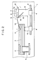
- Figs. 2 and 3 show cross sectional views of an embodiment of a magnetooptical recording apparatus of the invention.
- the apparatus of the embodiment differs from the conventional apparatus shown in Fig. 1 with respect to mainly the rotational member 7 in the upper portion of the carriage 5. Since the other portions are similar to those in the conventional apparatus, their descriptions are omitted. That is, an edge portion on the opposite side of the suspension arm 10 with respect to the shaft 8 of the rotational member 7 is formed as a triangular cam 7a and is come into contact with a fixed pin 21 arranged to the casing 1 of the apparatus main body. At this time, the floating magnetic head 11 is positioned near the inside of the outermost rim of the magnetooptical disc D as shown in Fig. 2.
- the carriage 5 When the portable cartridge C enclosing the magnetooptical disc D therein is loaded to or is ejected from the loading position (position shown in Fig. 2) to record, reproduce, or erase information onto/from the disc D, the carriage 5 is evacuated. When the carriage 5 is moved to the right shown in Fig. 3, the rotational member 7 rotates clockwise by the cam 7a which is in contact with the fixed pin. The suspension arm 10 coupled to the rotational member 7 and the floating magnetic head 11 are moved upward.
- the carriage 5 is moved backward and the backward movement is converted by the rotational member 7 into the movement in such a direction as to allow the floating magnetic head 11 to be away from the medium surface of the disc D.
- the floating magnetic head 11 is moved upward so as not to interfere the cartridge C. After that, the cartridge C is ejected out or loaded.
- Fig. 4 shows a cross sectional view of the second embodiment of a magnetooptical recording apparatus of the invention.
- the floating magnetic head 11 is supported to one end of the rotational member 7 through the suspension arm 10.
- the other edge of the rotational member 7 is bent downward to thereby form an L-shaped cam 7b and is come into contact with the fixed pin 21 arranged to the casing 1.
- the floating magnetic head 11 is positioned near the inside of the outermost rim of the magnetooptical disc D.
- the magnetooptical recording apparatus doesn't need a driving source to lift up or down the floating magnetic head suspension system and vertically moves the floating magnetic head suspension system by using the action in the disc radial direction of the carriage. Therefore, an increase in weight of the carriage due to the heavy part such as a solenoid or the like doesn't occur and the waiting time is reduced due to the use of the light carriage.
Applications Claiming Priority (2)
| Application Number | Priority Date | Filing Date | Title |
|---|---|---|---|
| JP23117390A JPH04111271A (ja) | 1990-08-31 | 1990-08-31 | 光磁気ディスク駆動装置 |
| JP231173/90 | 1990-08-31 |
Publications (2)
| Publication Number | Publication Date |
|---|---|
| EP0473413A2 true EP0473413A2 (de) | 1992-03-04 |
| EP0473413A3 EP0473413A3 (en) | 1992-04-01 |
Family
ID=16919463
Family Applications (1)
| Application Number | Title | Priority Date | Filing Date |
|---|---|---|---|
| EP19910307881 Withdrawn EP0473413A3 (en) | 1990-08-31 | 1991-08-28 | Magnetooptical recording apparatus |
Country Status (2)
| Country | Link |
|---|---|
| EP (1) | EP0473413A3 (de) |
| JP (1) | JPH04111271A (de) |
Cited By (3)
| Publication number | Priority date | Publication date | Assignee | Title |
|---|---|---|---|---|
| US5623457A (en) * | 1993-04-12 | 1997-04-22 | Sony Corporation | Photomagnetic disc drive system having a locking mechanism |
| US5815470A (en) * | 1994-08-11 | 1998-09-29 | Sony Corporation | Disc drive unit |
| CN1048349C (zh) * | 1993-12-17 | 2000-01-12 | 现代电子产业株式会社 | 小磁盘录放机的偏磁线圈磁头驱动装置 |
Families Citing this family (1)
| Publication number | Priority date | Publication date | Assignee | Title |
|---|---|---|---|---|
| JP2004274834A (ja) | 2003-03-06 | 2004-09-30 | Tamagawa Seiki Co Ltd | 駆動回路内蔵型サーボモータ |
Family Cites Families (2)
| Publication number | Priority date | Publication date | Assignee | Title |
|---|---|---|---|---|
| JP2679079B2 (ja) * | 1988-02-18 | 1997-11-19 | ソニー株式会社 | 光磁気記録方法 |
| EP0403266B1 (de) * | 1989-06-15 | 1994-08-24 | Matsushita Electric Industrial Co., Ltd. | Magneto-optisches Aufnahme- und/oder Wiedergabegerät |
-
1990
- 1990-08-31 JP JP23117390A patent/JPH04111271A/ja active Pending
-
1991
- 1991-08-28 EP EP19910307881 patent/EP0473413A3/en not_active Withdrawn
Cited By (3)
| Publication number | Priority date | Publication date | Assignee | Title |
|---|---|---|---|---|
| US5623457A (en) * | 1993-04-12 | 1997-04-22 | Sony Corporation | Photomagnetic disc drive system having a locking mechanism |
| CN1048349C (zh) * | 1993-12-17 | 2000-01-12 | 现代电子产业株式会社 | 小磁盘录放机的偏磁线圈磁头驱动装置 |
| US5815470A (en) * | 1994-08-11 | 1998-09-29 | Sony Corporation | Disc drive unit |
Also Published As
| Publication number | Publication date |
|---|---|
| EP0473413A3 (en) | 1992-04-01 |
| JPH04111271A (ja) | 1992-04-13 |
Similar Documents
| Publication | Publication Date | Title |
|---|---|---|
| US5644554A (en) | Magnetic head load/unload device, method and a magneto-optical disk apparatus using the same | |
| JP3763960B2 (ja) | ディスク装置 | |
| US5594708A (en) | Magnetooptical disc apparatus with magnetic head | |
| JP2940268B2 (ja) | 光磁気ディスク記録再生装置 | |
| JP2849160B2 (ja) | 光磁気記録再生装置 | |
| JPS61278058A (ja) | 光磁気記録再生装置 | |
| JP2977173B2 (ja) | 光磁気情報記録再生装置 | |
| JPH0676408A (ja) | 光磁気ディスク装置 | |
| US20020006082A1 (en) | Magneto-optic recording and reproduction device | |
| JP2608994B2 (ja) | 情報記録装置用浮上スライダ | |
| US5321686A (en) | Read-write head of an magneto-optical disc player with both heads magnetically coupled together | |
| JPH06243531A (ja) | 光磁気ディスク装置 | |
| JP3180839B2 (ja) | 光磁気ディスク装置 | |
| JP2836712B2 (ja) | 情報記録再生装置 | |
| JP2746306B2 (ja) | 光磁気記録再生装置 | |
| JPH07121925A (ja) | 光磁気ディスク装置 | |
| US5442596A (en) | Recording/reproducing apparatus having a magnetic head which is opened and closed together with a door | |
| JPH05274739A (ja) | 光磁気ディスク装置 | |
| JPH06349003A (ja) | 光磁気記録再生装置 | |
| JPH064805A (ja) | 光学式ディスク装置 | |
| JPH05342735A (ja) | 情報再生装置 | |
| JPH07326086A (ja) | 光磁気ディスク駆動装置 | |
| JPH05182207A (ja) | 光磁気ディスク装置 | |
| JPH04351770A (ja) | 情報記録再生装置 | |
| JPH0512741A (ja) | 光磁気デイスク装置 |
Legal Events
| Date | Code | Title | Description |
|---|---|---|---|
| PUAI | Public reference made under article 153(3) epc to a published international application that has entered the european phase |
Free format text: ORIGINAL CODE: 0009012 |
|
| PUAL | Search report despatched |
Free format text: ORIGINAL CODE: 0009013 |
|
| AK | Designated contracting states |
Kind code of ref document: A2 Designated state(s): DE FR GB IT NL |
|
| AK | Designated contracting states |
Kind code of ref document: A3 Designated state(s): DE FR GB IT NL |
|
| 17P | Request for examination filed |
Effective date: 19920817 |
|
| 17Q | First examination report despatched |
Effective date: 19941128 |
|
| STAA | Information on the status of an ep patent application or granted ep patent |
Free format text: STATUS: THE APPLICATION IS DEEMED TO BE WITHDRAWN |
|
| 18D | Application deemed to be withdrawn |
Effective date: 19950411 |