EP0473858A2 - Farbflüssigkristallanzeigevorrichtung - Google Patents
Farbflüssigkristallanzeigevorrichtung Download PDFInfo
- Publication number
- EP0473858A2 EP0473858A2 EP90314343A EP90314343A EP0473858A2 EP 0473858 A2 EP0473858 A2 EP 0473858A2 EP 90314343 A EP90314343 A EP 90314343A EP 90314343 A EP90314343 A EP 90314343A EP 0473858 A2 EP0473858 A2 EP 0473858A2
- Authority
- EP
- European Patent Office
- Prior art keywords
- light
- liquid crystal
- crystal display
- color
- display device
- Prior art date
- Legal status (The legal status is an assumption and is not a legal conclusion. Google has not performed a legal analysis and makes no representation as to the accuracy of the status listed.)
- Withdrawn
Links
Images


Classifications
-
- G—PHYSICS
- G02—OPTICS
- G02F—OPTICAL DEVICES OR ARRANGEMENTS FOR THE CONTROL OF LIGHT BY MODIFICATION OF THE OPTICAL PROPERTIES OF THE MEDIA OF THE ELEMENTS INVOLVED THEREIN; NON-LINEAR OPTICS; FREQUENCY-CHANGING OF LIGHT; OPTICAL LOGIC ELEMENTS; OPTICAL ANALOGUE/DIGITAL CONVERTERS
- G02F1/00—Devices or arrangements for the control of the intensity, colour, phase, polarisation or direction of light arriving from an independent light source, e.g. switching, gating or modulating; Non-linear optics
- G02F1/01—Devices or arrangements for the control of the intensity, colour, phase, polarisation or direction of light arriving from an independent light source, e.g. switching, gating or modulating; Non-linear optics for the control of the intensity, phase, polarisation or colour
- G02F1/13—Devices or arrangements for the control of the intensity, colour, phase, polarisation or direction of light arriving from an independent light source, e.g. switching, gating or modulating; Non-linear optics for the control of the intensity, phase, polarisation or colour based on liquid crystals, e.g. single liquid crystal display cells
- G02F1/133—Constructional arrangements; Operation of liquid crystal cells; Circuit arrangements
- G02F1/1333—Constructional arrangements; Manufacturing methods
- G02F1/1335—Structural association of cells with optical devices, e.g. polarisers or reflectors
- G02F1/133509—Filters, e.g. light shielding masks
- G02F1/133514—Colour filters
-
- G—PHYSICS
- G02—OPTICS
- G02F—OPTICAL DEVICES OR ARRANGEMENTS FOR THE CONTROL OF LIGHT BY MODIFICATION OF THE OPTICAL PROPERTIES OF THE MEDIA OF THE ELEMENTS INVOLVED THEREIN; NON-LINEAR OPTICS; FREQUENCY-CHANGING OF LIGHT; OPTICAL LOGIC ELEMENTS; OPTICAL ANALOGUE/DIGITAL CONVERTERS
- G02F1/00—Devices or arrangements for the control of the intensity, colour, phase, polarisation or direction of light arriving from an independent light source, e.g. switching, gating or modulating; Non-linear optics
- G02F1/01—Devices or arrangements for the control of the intensity, colour, phase, polarisation or direction of light arriving from an independent light source, e.g. switching, gating or modulating; Non-linear optics for the control of the intensity, phase, polarisation or colour
- G02F1/13—Devices or arrangements for the control of the intensity, colour, phase, polarisation or direction of light arriving from an independent light source, e.g. switching, gating or modulating; Non-linear optics for the control of the intensity, phase, polarisation or colour based on liquid crystals, e.g. single liquid crystal display cells
- G02F1/133—Constructional arrangements; Operation of liquid crystal cells; Circuit arrangements
- G02F1/1333—Constructional arrangements; Manufacturing methods
- G02F1/1335—Structural association of cells with optical devices, e.g. polarisers or reflectors
- G02F1/133504—Diffusing, scattering, diffracting elements
-
- G—PHYSICS
- G02—OPTICS
- G02F—OPTICAL DEVICES OR ARRANGEMENTS FOR THE CONTROL OF LIGHT BY MODIFICATION OF THE OPTICAL PROPERTIES OF THE MEDIA OF THE ELEMENTS INVOLVED THEREIN; NON-LINEAR OPTICS; FREQUENCY-CHANGING OF LIGHT; OPTICAL LOGIC ELEMENTS; OPTICAL ANALOGUE/DIGITAL CONVERTERS
- G02F2201/00—Constructional arrangements not provided for in groups G02F1/00 - G02F7/00
- G02F2201/30—Constructional arrangements not provided for in groups G02F1/00 - G02F7/00 grating
- G02F2201/305—Constructional arrangements not provided for in groups G02F1/00 - G02F7/00 grating diffraction grating
Definitions
- the present invention relates to a segment type color liquid crystal display device which displays predetermined characters and graphics etc. in color.
- Fig. 1 is a cross sectional diagram of the prior art segment type color liquid crystal display device 1.
- a color filter 5 is provided by a printing process or an electrodeposition color process etc. across nearly the entire surface of one side of the transparent substrate 4a, and a plurality of segment electrodes 6 are formed on predetermined display areas of the color filter 5.
- the color filter 5 is composed of red filters R, green filters G, and blue filters B, each of which are formed in narrow strips.
- the filters R, G, and B are each formed in the areas CF, and for example, black light-blocking layers are formed in the areas SP.
- the segment electrodes 6 are composed of electrodes for red, electrodes for green, and electrodes for blue, which correspond to the red filters R, green filters G, and blue filters B respectively.
- An orientation film 7a is formed on the surface of the transparent substrate 4a where the color filter 5 and the segment electrodes 6 are formed.
- a plurality of common electrodes 8 are formed on the surface of one side of the transparent substrate 4b, across the areas which include the segment electrodes 6, and further, an orientation film 7b is formed on that surface.
- the transparent substrates 4a and 4b are arranged so that the surface on which the respective orientation films 7a and 7b are formed face each other.
- a twisted nematic liquid crystal layer 9 is sandwiched between the transparent substrates 4a and 4b, and is sealed with a sealant 10.
- the polarizer plates 11 and 12 are provided on the surfaces of the transparent substrates 4a and 4b respectively which are on the sides opposite from the liquid crystal layer 9.
- the polarizer plates 11 and 12 are arranged so as to achieve parallel polarization, and when voltage is not applied, light is allowed to pass through the color liquid crystal display device 1, performing so-called normally white display.
- Normally white display is a display method wherein the background is for example white in color, and which displays the desired configuration by applying voltage to the liquid crystal layer 9 corresponding to the configuration to be displayed, thereby changing the light distribution state of the molecules in the liquid crystal and blocking the light.
- color filter 5 is formed by the minute rectangular shaped filters R, G, and B as shown in FIG. 2, and the transmitted light turns white due to the mixing of red light, green light, and blue light.
- white is displayed as the background color in the color liquid crystal display device 1. Therefore, in case for example, voltage is applied only to the electrodes for blue which make up the segment electrodes 6, the blue light is blocked and yellow is displayed due to the mixing of red light and green light.
- color liquid crystal display device 1 When the above mentioned color liquid crystal display device 1 is used in audio devices, OA (Office Automation) devices, or home electrical products, there are cases where a transparent film preprinted with numbers, characters and graphics etc. is arranged on the front of the color liquid crystal display device 1.
- a transparent film preprinted with numbers, characters and graphics etc. is arranged on the front of the color liquid crystal display device 1.
- characters and graphics such as the characters "R" and "L” indicating the left and right channels, and the numbers indicating the recording playback level, which need not be displayed using the color liquid crystal display device 1, that is to say the characters and graphics etc. which may always be in a visible state, are printed on a transparent film and arranged on the front of the color liquid crystal display device 1.
- the color filter 5 as mentioned above was composed of a plurality of filters formed in minute rectangular shapes arranged, for example, in a matrix, and hence there was a limit on the size of the characters.
- the color filter 5 has the 3 types of color filter R, G and B as 1 unit area, and in this 1 unit area, white color is obtained by the mixing of the transmitted light.
- area A1 only red light is transmitted, and sometimes area AO which is close to area A1 appears to be colored red and blurred.
- area AO which is close to areas A2 and A4 appears to be colored green and blurred.
- area A3 only blue light is transmitted, and sometimes area Ao which is close to area A3 appears to be colored blue and blurred. That is to say, the phenomenon in which the periphery of a character appears blurred occurs because the color balance of the transmitted light breaks down.
- the object of the invention is to solve the above mentioned problem and to provide a color liquid crystal display device with markedly improved display quality.
- the invention is a color liquid crystal display device comprising a liquid crystal display element having a pair of light-transmissive substrates with a liquid crystal layer sandwiched between them, a plurality of color selection members provided across nearly the entire surface of the side of the light-transmissive substrates facing the liquid crystal layer which select one color for the transmitted light from among a plurality of predetermined colors, light-transmissive display electrodes provided on the surfaces of the side of the light-transmissive substrates facing the liquid crystal layer, formed corresponding to each of the plurality of color selection members within the predetermined display areas;
- normally white display when voltage is not applied to the liquid crystal layer by the display electrodes, so-called normally white display can be performed by allowing the light from the light source to be transmitted through the liquid crystal display element.
- white is displayed as the background color in the liquid crystal display element through the mixing of red light, green light and blue light.
- voltage to the display electrodes formed corresponding to each of the plurality of color selection members within the predetermined display areas the transmission of light is blocked in the areas corresponding to the display electrodes to which voltage has been applied, and therefore a specific color is displayed in the display areas. For example, red is displayed in the display areas by blocking green light and blue light, and by blocking the red light, greenish blue (cyan) is displayed in the display areas through the mixing of green light and blue light.
- light-blocking members of predetermined configurations are disposed on the surface of one side of the liquid crystal display element, that is to say the surface on the side opposite to the light source, and the predetermined configurations are displayed on the color liquid crystal display device by blocking the light from the light source with the light-blocking members.
- the light-scattering plate is disposed between the light source and the liquid crystal display element, or between the liquid crystal display element and the light-blocking members.
- the light from the light source can be scattered by this light-scattering plate. Therefore, around the periphery of the light-blocking members, the light which was originally supposed to be blocked by the light-blocking member comes to be transmitted. Because of this, around the periphery of the light-blocking members, the color balance of the transmitted light breaks down and only a specific color of light is transmitted, thereby preventing the colored and blurred appearance of the peripheral part of the light-blocking members. Based upon this, the display quality of the color liquid crystal display device is markedly improved.
- FIG. 3 is a cross-sectional diagram showing the construction of the color liquid crystal display device 21, which is one embodiment of the invention.
- the color liquid crystal display device 21 is composed of the back light 22, the liquid crystal display element 23, the light-scattering plate 24 and the transparent substrate 25 stacked in this order.
- the back light 22 is for example composed of a hot cathode tube etc.
- the characters and numbers etc. to be discussed later are printed on the transparent substrate 25.
- the liquid crystal display element 23 has a pair of transparent substrates 26a and 26b which are made of glass or plastics etc., and the color filter 27 is formed across nearly the entire surface of one side of the transparent substrate 26a.
- the color filter 27 is, for example, composed of color filters of 3 colors formed in fine rectangular shapes, for instance a red filter R, a green filter G and a blue filter B, and the black light-blocking layers BL provided in the spaces between all of the filters, and is formed by a process such as a dyeing process, a printing process, an electrodeposition process or a pigment dispersion process.
- the segment electrodes 28 are formed on the color filter 27.
- the orientation film 29a is formed on the transparent substrate 26a, on which the color filter 27 and the segment electrodes 28 are formed.
- the common electrodes 30 are formed on the surface of one side of the transparent substrate 26b, at least in the areas that include the segment electrodes 28, and further, the orientation film 29b is formed on that surface.
- the transparent substrates 26a and 26b are arranged so that the surfaces on which the respective orientation films 29a and 29b are formed, face each other.
- the liquid crystal layer 31 is sandwiched between the transparent substrates 26a and 26b, and is sealed by the sealant 32.
- the polarizer plates 33 and 34 respectively are disposed on the surfaces of the substrates 26a and 26b which are opposite from the liquid crystal layer 31.
- a polyamide resin for example is used in the orientation films 29a and 29b.
- the orientation films 29a and 29b are formed for example to a thickness of 600A, the orientation of the liquid crystal molecules is twisted by 90° between the transparent substrates 26a and 26b, and for example as in forming a levorotatory liquid crystal layer, it undergoes a rubbing process with nylon fabric.
- plastic spacers are put between these substrates.
- the space between the substrates is for example established at 5 micron by these spacers.
- Epoxy resin for example is used as the sealant 32 for sealing the liquid crystal layer 31.
- a phenyl cyclohexane compound liquid crystal, for example, is chosen for the liquid crystal layer 31.
- cholesteric nonanoate is added to this liquid crystal layer, to make it levorotatory.
- orientation films 29a and 29b may also undergo rubbing treatment that will twist the direction of orientation of the liquid crystal molecules between the crystal layer dextrorotatory.
- a phenyl cyclohexane compound liquid crystal with CB-15 (made by the Merck Co.) added, is used as a dextrorotatory chiral material in the liquid crystal layer 31.
- FIG. 4 is a plane view of the color liquid crystal display device 21.
- the case of using the color liquid crystal display device 21 as a level meter provided in a cassette tape recorder or other audio device is explained.
- a plurality of rectangular areas and a plurality of display characters are set up on the color liquid crystal display device 21.
- the segment electrodes 28, which are formed corresponding to the rectangular areas, are arranged in the plurality of rectangular areas.
- the plurality of display characters for example the Roman letters “L” and “R”, the numerals "40", “30”, “20”, “10", “5", “3” and “0”, and the symbols "-", "+”, and “I”, are formed by printing or pasting etc. onto the surface of the transparent substrate 25, the light-blocking members which are formed in configurations corresponding to the respective characters.
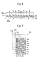
- FIG. 5 is an enlarged plane view of the color filter 27, and FIG. 6 is an enlarged cross-sectional diagram of the area around the color filter 27.
- the color filter 27, which is a color selection members is provided across nearly the entire color selection members is provided across nearly the entire surface of the transparent substrate 26a.
- the color filter 27 is formed by disposing all of the filters R, G and B, for red, green and blue, in a matrix form or mosaic form.
- red filters are indicated by the reference symbol R
- green filters are indicated by the reference symbol G
- blue filters are indicated by the reference symbol B.
- the size of the filters R, G and B is minute, and of a size indistinguishable by the naked eye.
- the space L3 between the filters is determined by the manufacturing precision of the color filter by a photo process etc., and it is generally from 15 micron to 40 micron.
- the arrangement R-G-B is repeated in the direction of the width of the filters E2, and the arrangement R-B-G is repeated in the direction of the length of the filters E1.
- the shape of the filters R, G and B may be made square or another shape.
- the black light-blocking layer BL is formed between all of the filters R, G and B.
- the light-blocking layer BL is formed with chrome (Cr) or black pigment etc.
- FIG. 7 is an enlarged plane view of a segment electrode 28.
- the quadrilateral color filters R, G and B for the 3 colors red, green and blue, are disposed in a plurality of matrix forms or mosaic forms on the transparent substrate 26a, and the invention is the color liquid crystal display device 21 which has transparent electrodes set up as the signal lines, so as to connect in sequence the segment electrodes corresponding to the color filters of the same color.
- the segment electrode 28 is made up of electrodes Sr for red, electrodes Sg for green and electrodes Sb for blue.
- the electrodes Sr, Sg and Sb are formed in the areas that correspond to the filters R, G and B respectively, and each of the electrodes Sr, Sg and Sb respectively are connected by the transparent electrodes 41 r, 41 g and 41 which serve as signal lines.
- this connection method it is possible to display the 7 colors red, yellow, green, greenish blue (cyan), Blue, white, and pink (magenta) in the desired display areas, by freely selecting the segment electrodes to which voltage is applied.
- FIG. 8 is a block diagram showing the electrical construction of the color liquid crystal display device 21.
- the back light 22 is disposed on the side of the polarizer plate 34 that is opposite from the liquid crystal display element 23 , and a plurality of colors, as mentioned later, are displayed on the color liquid crystal display device 21 by transmitting/blocking the light from the back light 22 using the liquid crystal display element 23.
- the liquid crystal element is controlled by the liquid crystal element driver 45.
- the liquid crystal element driver 45 applies voltage to the common electrodes 30 through the signal lines t1 based upon the display control signals from the display controller 46, and applies voltage to the selected segment electrodes 28 through the signal line group 12. By this means, color display can be performed on the color liquid crystal display device 21.
- the molecules which are closest to the transparent substrate 26b are in a state or orientation which is perpendicular to the surface of the paper in FIG. 3, as the transparent substrate 26a is approached they gradually twist toward the right, and the liquid crystal molecules that are closest to the transparent substrate 26a are in a state of orientation which is parallel to the surface of the paper in FIG. 3.
- Normally white display is a display method which displays the desired configurations by allowing light to be transmitted through the liquid crystal layer 31 when voltage is not being applied, with a white background for example, and where light is blocked by changing the orientation state of the liquid crystal molecules with the application of voltage to the liquid crystal layer 31 in the areas that correspond to the configurations to be displayed. Therefore, in order that the polarizing direction of the polarizer plates 33 and 34 will achieve parallel polarization, they are disposed for example, so that the polarizing direction of the polarizer plate 34 is in the direction perpendicular to the surface of the paper in FIG. 3, and the polarizing direction of the polarizer plate 33 is in a direction parallel to the surface of the paper in FIG. 3.
- the light which is transmitted through the polarizer plate 34 is twisted 90 by the liquid crystal layer 31, and it can be transmitted through the polarizer plate 33.
- the color filter 27 is formed by the fine rectangular filters R, G and B as shown in the above mentioned FIG. 5, and the transmitted light becomes white light through the mixing of red light, green light and blue light. In other words, white is displayed as the background color in the color liquid crystal display device 21 when voltage is not applied.
- the liquid crystal molecules of the liquid crystal layer 31 to which voltage is applied orient themselves in the direction of the electric field. Therefore, the linearly polarized light transmitted through the polarizer plate 34 in the direction perpendicular to the surface of the paper in FIG. 3 is transmitted through the liquid crystal layer 31 in nearly the same state of polarization.
- the light which was transmitted through the liquid crystal layer 31 cannot be transmitted through the polarizer plate 33, because the polarizing direction of the polarizer plate 33 is in the direction parallel to the surface of the paper in FIG. 3.
- the liquid crystal layer 31 operates as a light shutter based on the operation of voltage (ON) and the non-operation of voltage (OFF).
- the relationship among the ON/OFF state of the segment electrodes, the operation of the liquid crystal layer as a light shutter, and the display color is shown in Table 1 below.
- FIG. 9 is a diagram for explaining the effect of the light-scattering plate 24.
- the transmitted light which has been transmitted through the filters R, G and B, is scattered by the light-scattering plate 24.
- the transparent substrate 25 Even the light which was originally supplied to be blocked by the light-blocking area F can be transmitted through the transparent substrate 25.
- the unit area D even in a case where the area corresponding to a red filter R is blocked by the light-blocking area F, and the color balance of the transmitted light breaks down, a part of the red light transmitted through the red filter R is transmitted through the transparent substrate 25. By this means it is possible to maintain the color balance in the unit area D.
- the light-scattering plate 24 was provided between the liquid crystal display element 23 and the transparent substrate 25, however, it may also be provided between the back light 22 and the liquid crystal display element 23. Further, it is also possible to roughen the surfaces of the transparent substrates 26a and 26b on which the polarizer plates 33 and 34 respectively are provided, instead of providing the light-scattering plate 24.
- twisted nematic liquid crystal wherein the liquid crystal molecules are twisted by an angle of 90°, was used as the liquid crystal layer 31, however, super twisted nematic liquid crystal, with a twisted angle of 180 ° to 2700, may also be used.
Landscapes
- Physics & Mathematics (AREA)
- Nonlinear Science (AREA)
- Chemical & Material Sciences (AREA)
- Crystallography & Structural Chemistry (AREA)
- General Physics & Mathematics (AREA)
- Optics & Photonics (AREA)
- Mathematical Physics (AREA)
- Liquid Crystal (AREA)
- Devices For Indicating Variable Information By Combining Individual Elements (AREA)
Applications Claiming Priority (2)
| Application Number | Priority Date | Filing Date | Title |
|---|---|---|---|
| JP2237840A JPH04116682A (ja) | 1990-09-07 | 1990-09-07 | カラー液晶表示装置 |
| JP237840/90 | 1990-09-07 |
Publications (2)
| Publication Number | Publication Date |
|---|---|
| EP0473858A2 true EP0473858A2 (de) | 1992-03-11 |
| EP0473858A3 EP0473858A3 (en) | 1992-08-26 |
Family
ID=17021193
Family Applications (1)
| Application Number | Title | Priority Date | Filing Date |
|---|---|---|---|
| EP19900314343 Withdrawn EP0473858A3 (en) | 1990-09-07 | 1990-12-27 | Color liquid crystal display device |
Country Status (5)
| Country | Link |
|---|---|
| US (1) | US5132830A (de) |
| EP (1) | EP0473858A3 (de) |
| JP (1) | JPH04116682A (de) |
| KR (1) | KR940001906B1 (de) |
| TW (1) | TW218040B (de) |
Families Citing this family (21)
| Publication number | Priority date | Publication date | Assignee | Title |
|---|---|---|---|---|
| JP2875363B2 (ja) | 1990-08-08 | 1999-03-31 | 株式会社日立製作所 | 液晶表示装置 |
| JPH04317027A (ja) * | 1991-04-16 | 1992-11-09 | Seiko Instr Inc | 多色表示装置 |
| US5528720A (en) | 1992-03-23 | 1996-06-18 | Minnesota Mining And Manufacturing Co. | Tapered multilayer luminaire devices |
| US6002829A (en) | 1992-03-23 | 1999-12-14 | Minnesota Mining And Manufacturing Company | Luminaire device |
| FR2693005B1 (fr) * | 1992-06-26 | 1995-03-31 | Thomson Lcd | Disposition d'encapsulation et de passivation de circuit pour écrans plats. |
| US5278681A (en) * | 1992-09-02 | 1994-01-11 | At&T Bell Laboratories | Combined color and monochrome display |
| US5481385A (en) * | 1993-07-01 | 1996-01-02 | Alliedsignal Inc. | Direct view display device with array of tapered waveguide on viewer side |
| JPH07114018A (ja) * | 1993-10-15 | 1995-05-02 | Rohm Co Ltd | カラー液晶表示装置 |
| US5629784A (en) * | 1994-04-12 | 1997-05-13 | Ois Optical Imaging Systems, Inc. | Liquid crystal display with holographic diffuser and prism sheet on viewer side |
| US5521726A (en) * | 1994-08-26 | 1996-05-28 | Alliedsignal Inc. | Polarizer with an array of tapered waveguides |
| JP3040667B2 (ja) * | 1994-08-29 | 2000-05-15 | シャープ株式会社 | 透過型表示装置の輝点欠陥修正方法 |
| US5657408A (en) * | 1994-12-23 | 1997-08-12 | Alliedsignal Inc. | Optical device comprising a plurality of units having at least two geometrically-differentiated tapered optical waveguides therein |
| FR2737799B1 (fr) * | 1995-08-11 | 1997-10-17 | Thomson Multimedia Sa | Perfectionnement au dispositif d'affichage comportant un systeme d'eclairage arriere fournissant une lumiere collimatee |
| JP3339334B2 (ja) | 1996-12-05 | 2002-10-28 | 松下電器産業株式会社 | 反射型液晶表示素子 |
| JP3210274B2 (ja) | 1997-08-25 | 2001-09-17 | 松下電器産業株式会社 | 反射型液晶表示素子 |
| US6211934B1 (en) | 1997-12-24 | 2001-04-03 | Honeywell Inc. | Method of and apparatuses for reducing infrared loading on display devices |
| US5963284A (en) * | 1998-04-01 | 1999-10-05 | Ois Optical Imaging Systems, Inc. | LCD with diffuser having diffusing particles therein located between polarizers |
| JP2000019500A (ja) * | 1998-06-29 | 2000-01-21 | Toshiba Corp | 液晶表示装置 |
| US6639638B1 (en) * | 1999-08-27 | 2003-10-28 | International Business Machines Corporation | LCD cover optical structure and method |
| JP4412441B2 (ja) * | 2000-07-11 | 2010-02-10 | 日本電気株式会社 | 液晶表示装置 |
| KR100720411B1 (ko) * | 2000-10-25 | 2007-05-22 | 엘지.필립스 엘시디 주식회사 | 액정 디스플레이 패널 및 그 제조방법 |
Family Cites Families (9)
| Publication number | Priority date | Publication date | Assignee | Title |
|---|---|---|---|---|
| DE2329618A1 (de) * | 1973-06-09 | 1975-01-02 | Fraunhofer Ges Forschung | Anordnung zur vielfarbigen anzeige, bestehend aus lichtquelle und linearpolarisationsfilter |
| US4171874A (en) * | 1975-02-03 | 1979-10-23 | General Electric Company | Evenly illuminated display devices |
| DE3032988A1 (de) * | 1980-09-02 | 1982-04-15 | Blaupunkt-Werke Gmbh, 3200 Hildesheim | Fluessigkristallanzeige |
| JPS58176677A (ja) * | 1982-04-09 | 1983-10-17 | 株式会社日立製作所 | 液晶表示装置 |
| JPS5936282A (ja) * | 1982-08-24 | 1984-02-28 | セイコーエプソン株式会社 | カラ−表示装置 |
| US4506956A (en) * | 1983-03-29 | 1985-03-26 | Xerox Corporation | Multicolor liquid crystal display with a dead front |
| JPS60203915A (ja) * | 1984-03-28 | 1985-10-15 | Matsushita Electric Ind Co Ltd | 大型液晶デイスプレイ |
| US4721366A (en) * | 1985-10-07 | 1988-01-26 | Rca Corporation | Illumination of a liquid crystal display |
| JPS61179123A (ja) * | 1986-02-07 | 1986-08-11 | 東芝テック株式会社 | 電気掃除機の吸込口体 |
-
1990
- 1990-08-31 TW TW079107309A patent/TW218040B/zh active
- 1990-09-07 JP JP2237840A patent/JPH04116682A/ja active Pending
- 1990-12-18 KR KR1019900020854A patent/KR940001906B1/ko not_active Expired - Fee Related
- 1990-12-19 US US07/630,039 patent/US5132830A/en not_active Expired - Lifetime
- 1990-12-27 EP EP19900314343 patent/EP0473858A3/en not_active Withdrawn
Also Published As
| Publication number | Publication date |
|---|---|
| EP0473858A3 (en) | 1992-08-26 |
| JPH04116682A (ja) | 1992-04-17 |
| TW218040B (de) | 1993-12-21 |
| US5132830A (en) | 1992-07-21 |
| KR940001906B1 (ko) | 1994-03-11 |
| KR920006785A (ko) | 1992-04-28 |
Similar Documents
| Publication | Publication Date | Title |
|---|---|---|
| US5132830A (en) | Color liquid crystal display device having a light scattering plate and light blocking members | |
| US5216414A (en) | Color liquid crystal display device | |
| US5642176A (en) | Color filter substrate and liquid crystal display device | |
| US6005654A (en) | Liquid crystal display device intended, in particular, to form a color image display screen | |
| EP0351200B1 (de) | Flüssigkristall-Anzeigevorrichtung | |
| EP0434220B1 (de) | Farbige Flüssigkristallanzeigevorrichtung | |
| JPH04355722A (ja) | カラー液晶表示素子 | |
| US4964702A (en) | Liquid crystal display device having a light shielding layer being a complementary color to the color filter | |
| JP2001194658A (ja) | 液晶表示装置 | |
| JPS60159823A (ja) | カラ−液晶表示装置 | |
| EP0435676B1 (de) | Flüssigkristall-Anzeigevorrichtung zur Anzeige von mehreren oder allen Farben | |
| JP2644614B2 (ja) | カラー液晶表示装置 | |
| KR100635947B1 (ko) | 컬러 필터 기판 및 이를 포함하는 액정 표시 장치 | |
| JPH05313158A (ja) | カラー液晶ディスプレイ | |
| JPS62148926A (ja) | カラ−液晶表示素子 | |
| JPH0497134A (ja) | カラー液晶表示装置 | |
| JP2644615B2 (ja) | カラー液晶表示装置 | |
| KR0122051Y1 (ko) | 액정 디스플레이의 시일 프린트 | |
| JPH0311317A (ja) | 液晶表示装置 | |
| JPH0455825A (ja) | カラー液晶表示装置 | |
| JPH0455827A (ja) | カラー液晶表示装置 | |
| JPH0333721A (ja) | カラー液晶表示装置とその製造方法 | |
| JPH04284418A (ja) | 液晶表示装置 | |
| JPH0455830A (ja) | カラー液晶表示装置 | |
| JPH0836172A (ja) | 液晶表示装置 |
Legal Events
| Date | Code | Title | Description |
|---|---|---|---|
| PUAI | Public reference made under article 153(3) epc to a published international application that has entered the european phase |
Free format text: ORIGINAL CODE: 0009012 |
|
| 17P | Request for examination filed |
Effective date: 19910102 |
|
| AK | Designated contracting states |
Kind code of ref document: A2 Designated state(s): DE FR GB NL |
|
| PUAL | Search report despatched |
Free format text: ORIGINAL CODE: 0009013 |
|
| AK | Designated contracting states |
Kind code of ref document: A3 Designated state(s): DE FR GB NL |
|
| 17Q | First examination report despatched |
Effective date: 19931223 |
|
| STAA | Information on the status of an ep patent application or granted ep patent |
Free format text: STATUS: THE APPLICATION IS DEEMED TO BE WITHDRAWN |
|
| 18D | Application deemed to be withdrawn |
Effective date: 19940503 |