EP0474478A2 - Kombinierte Zentrifugal- und Vakuumpumpe - Google Patents
Kombinierte Zentrifugal- und Vakuumpumpe Download PDFInfo
- Publication number
- EP0474478A2 EP0474478A2 EP91308102A EP91308102A EP0474478A2 EP 0474478 A2 EP0474478 A2 EP 0474478A2 EP 91308102 A EP91308102 A EP 91308102A EP 91308102 A EP91308102 A EP 91308102A EP 0474478 A2 EP0474478 A2 EP 0474478A2
- Authority
- EP
- European Patent Office
- Prior art keywords
- vacuum pump
- pump
- centrifugal
- rotor
- shaft
- Prior art date
- Legal status (The legal status is an assumption and is not a legal conclusion. Google has not performed a legal analysis and makes no representation as to the accuracy of the status listed.)
- Granted
Links
Images





Classifications
-
- F—MECHANICAL ENGINEERING; LIGHTING; HEATING; WEAPONS; BLASTING
- F04—POSITIVE - DISPLACEMENT MACHINES FOR LIQUIDS; PUMPS FOR LIQUIDS OR ELASTIC FLUIDS
- F04D—NON-POSITIVE-DISPLACEMENT PUMPS
- F04D7/00—Pumps adapted for handling specific fluids, e.g. by selection of specific materials for pumps or pump parts
- F04D7/02—Pumps adapted for handling specific fluids, e.g. by selection of specific materials for pumps or pump parts of centrifugal type
- F04D7/04—Pumps adapted for handling specific fluids, e.g. by selection of specific materials for pumps or pump parts of centrifugal type the fluids being viscous or non-homogenous
- F04D7/045—Pumps adapted for handling specific fluids, e.g. by selection of specific materials for pumps or pump parts of centrifugal type the fluids being viscous or non-homogenous with means for comminuting, mixing stirring or otherwise treating
-
- F—MECHANICAL ENGINEERING; LIGHTING; HEATING; WEAPONS; BLASTING
- F05—INDEXING SCHEMES RELATING TO ENGINES OR PUMPS IN VARIOUS SUBCLASSES OF CLASSES F01-F04
- F05B—INDEXING SCHEME RELATING TO WIND, SPRING, WEIGHT, INERTIA OR LIKE MOTORS, TO MACHINES OR ENGINES FOR LIQUIDS COVERED BY SUBCLASSES F03B, F03D AND F03G
- F05B2210/00—Working fluid
- F05B2210/10—Kind or type
- F05B2210/13—Kind or type mixed, e.g. two-phase fluid
- F05B2210/132—Pumps with means for separating and evacuating the gaseous phase
Definitions
- the present invention relates to a combined centrifugal/vacuum pump with an intermediate wall separating the centrifugal pump from the vacuum pump and, specifically, to an intermediate wall having a non-annular volume therein.
- such pumps utilize a separate vacuum pump, piping from the centrifugal pump to the vacuum pump, a separate motor and motor mount for the vacuum pump, etc., in order to exhaust the gas which has been separated from the suspension so that the suspension may be effectively pumped by the pump impeller.
- U.S. Patent No. 3,230,890 discloses a centrifugal pump for removing gas from low consistency suspensions or from water having either a built-in vacuum pump or an external vacuum pump.
- FIG. 1 illustrates the prior art centrifugal pump, with the volute being omitted, provided with a vacuum pump on the same shaft as impeller.
- the prior art pump of FIG. 1 has a fluidizing impeller 12 rotating , in an ordinary medium consistency pump housing.
- the impeller 12 has through bores 14 for allowing the air accumulated at the front side of the impeller 12 to be drawn by means of the vacuum pump 10 to the back side of the impeller 12.
- the impeller has also so-called back vanes 16 on the back side thereof for separating the fiber suspension from the medium being drawn through the openings 14 in the impeller plate 18.
- the main purpose of the back vanes 16 is to pump the fiber suspension back to the pump volute and thus prevent the fibers from entering the vacuum pump 10, as the risk of damaging the vacuum pump 10 rises dramatically if the fibers are allowed to enter the vacuum pump 10.
- the vacuum pump 10 is a so-called liquid ring pump which has been arranged on the pump shaft 20 behind an intermediate plate 22 in which only a narrow ring- shaped duct 24 is provided which duct surrounds the shaft 20 or the impeller extension 26 for allowing the gas to flow towards the vacuum pump.
- the intermediate plate 22 is also provided with a ring-shaped channel 28 and a narrow duct 30 leading thereto for introducing make-up air to the vacuum pump while the pump is running.
- the duct 30 is connected via channel 32 to a vacuum regulating valve (not shown).
- the vacuum pump housing 34 is provided with a conduit 36 for feeding liquid to the liquid ring pump 10 for maintaining the amount of liquid substantially constant therein.
- Conduit 36 is connected to the outer, eccentric circumference 38 of the liquid ring pump 10. In other words, the conduit 36 leads exclusively and directly to the liquid ring.
- the suction opening for the liquid ring pump 10 is provided, naturally, on the side of the centrifugal impeller 12.
- the discharge channel (not shown) for the gas to be removed from the pump 10 is arranged at the opposite side of the vacuum pump 10, i.e. on the back side of the vacuum pump relative to the centrifugal impeller 12.
- the air removal capacity has been significantly lower than required, i.e. the vacuum created has not reached a sufficiently high level.
- the discharge pressure of the vacuum pump has been found to be too low.
- the discharge pressure of the vacuum pump is too low the pumped material cannot be conveyed to the top of the mass tower, and an additional pump must be installed for that purpose.
- the open annular volume in the intermediate plate 22 of prior art pump has a tendency to become clogged by the fibers.
- the axial gap 40 between the vanes 42 of the vacuum pump 10 and the axially adjacent walls 44 of the vacuum pump housing are not adjustable but are positioned with a distance or clearance of about 0.4 mm.
- the reasons for such relatively large clearance is the fact that there are a number of factors which render it is impossible to further decrease the clearance 40 as the various components of the pump are installed on the shaft or around the shaft starting from the drive end 46 of the shaft.
- the dimensions of the components effect the clearance 40.
- the result of too wide a clearance is, of course, an insufficient vacuum.
- Another reason for the wide clearance 40 may also be the fact that the shaft 20 of the pump tends to flex somewhat during operation creating the risk of mechanical contact between the vacuum pump vanes and the housing walls 44.
- the large clearance 40 has been provided intentionally to ensure long lasting operation of the pump.
- the pump in accordance with the present invention is designed to eliminate most or all of the above problems. Accordingly the pump of the present invention is provided with an intermediate plate separating the centrifugal pump from the vacuum pump which is, preferably, a liquid-ring pump. A non- annular volume is provided within this intermediate plate which non-annular volume communicates with the inside of the vacuum pump chamber and the outside of the pump for permitting gas as well as liquid to flow through the non-annular volume into the vacuum pump chamber.
- the non-annular opening provided in the intermediate plate is located at or in close proximity to the shaft in accordance with the pressure distribution present in the volute. For example, if located at the point of highest pressure, less vacuum or no additional vacuum is required to discharge the gas from the volute.
- the non- annular opening may be located at the point of lowest pressure just behind the pump outlet when viewed in the direction of rotation of the pump impeller thereby preventing the fibers from being drawn into the volute together with the gas.
- non-annular opening is preferably connected to a non-annular volume in the intermediate plate.
- an open annular volume is arranged within the back vanes of the centrifugal impeller by providing an annular surface substantially parallel to the shaft or the impeller extension sleeve either at the back plate of the impeller or at the radially inner edges of the back vanes so that a circular space or gas flow passage is formed between one side of said annular surface and the intermediate wall or between one side of the surface and the impeller back plate depending on where the annular surface is attached.
- the open circular gas flow passage is useful for equalizing the pressure differences in the space between the back vanes of the centrifugal impeller.
- the pump of the present invention may also be provided with means for introducing a liquid into the pump, and especially into the non-annular volume and air flow ducts of the pump for flushing these critical locations with a liquid such as flushing water and freeing the pump from fibers which otherwise tend to block the flow path of the pump.
- the flushing ducts may also he used to supply working liquid to the liquid ring of the vacuum pump.
- the pump of the present invention also provides means for adjusting the relative axial position of the vacuum pump rotor relative to the front and rear wall of the vacuum pump chamber thereby providing significantly smaller operational clearances therebetween.
- This may be achieved by either adjusting the axial position of the rotor with respect to the shaft, for example, by the addition of shims between respective shoulders of the vacuum pump rotor and shaft.
- the relative axial position of the vacuum pump rotor with respect to the vacuum pump chamber may also be optimized by adjusting the axial position of the shaft with respect to the vacuum pump chamber and the centrifugal pump body, in which case the vacuum pump rotor is fixedly attached to the shaft.
- the relative axial position of the vacuum pump rotor and the vacuum pump chamber is optimized by adjusting the vacuum pump chamber with respect to the rotor and the centrifugal pump body, for example, by adjustment screws as is further described in detail below.
- ports for the admission of make-up air for the control of the vacuum pump may be provided at the rear wall of the vacuum pump.
- rear wall of the vacuum pump is meant that wall which is located opposite the air inlet port and distal the centrifugal pump housing.
- Axial clearance between the vacuum pump rotor and the vacuum pump chamber walls may also be adjusted by providing a rotor with rotor blades which are slightly tapered in radial direction or wherein the side walls of the vacuum chamber are slightly tapered in radial direction relative to the shaft to account the slight bending or flexing of the shaft during operation of the vacuum pump.
- the vacuum pump may also be designed as that the air inlet port and the outlet port are on the same site of the pump within the intermediate plate and the rotor central portion is tapered conically toward the gas outlet of the pump so as to prevent the formation of a gas pocket around the rotor central portion.
- the pump of the present invention is also provided with means for introducing a sealing liquid to the clearances between the vacuum pump rotor and adjacent side walls for sealing the same and thus increasing the pumping action of the device.
- the sealing liquid may be introduced separately to one or both sides of the vacuum pump chamber so that it can flow into and seal the space or clearance between the pump rotor and adjacent side walls of the vacuum pump.
- the sealing liquid may also be fed to the spaces through a single conduit leading through the central portion of the vacuum pump rotor.
- a control valve for regulating the vacuum of the vacuum pump may also be directly attached at the end of the make-up air channel.
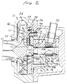
- FIG. 2 shows a vertical cross-sectional view of the centrifugal pump in accordance with the present invention.
- the centrifugal pump includes a housing 50 including an inlet channel 52 and a volute 54.
- the housing 50 is attached to the pump frame 56 having at one end thereof the bearing assembly (not shown) for supporting the pump shaft 58 at the end of which the centrifugal impeller 60 having a plurality of openings 62 in its back plate 64 is mounted.
- the centrifugal impeller 60 is further provided with front vanes, i.e. working vanes 66, on the front side thereof and with back vanes 68 on the opposite side of the back plate 64.
- a rotor having fluidizing blades 49 thereon may be mounted on the shaft 58 in front of impeller 60 for pumping fiber suspensions of medium or high consistency.
- the fluidizing blades may extend through the pump inlet 52 or be located only outside the inlet and within the pulp containing vessel.
- the sealing assembly Located between the bearing unit and the centrifugal impeller 60 is the sealing assembly (not shown). Between the sealing assembly and the centrifugal impeller 60 there is mounted a vacuum pump 70 on the same shaft 58 as the centrifugal impeller 60.
- the vacuum pump 70 is separated from the volute 54, i.e. from the space housing the centrifugal impeller 60, by means of an intermediate plate 72 which also forms the head or the front wall 112 of the vacuum pump 70.
- plate 72 has a non-annular opening 74 in the vicinity of the shaft 58 for permitting the gas to flow from the space behind the centrifugal impeller 60 to the vacuum pump 70.
- Non-annular opening 74 preferably extends proximate shaft 58 or, depending on the design, proximate impeller extension sleeve 92, and communicates with the vacuum pump 70 through preferably non-annular volume 146 and gas inlet port 94.
- an entry port 88 and narrow conduit 71 is provided within the vacuum pump housing for introducing a liquid, such as water, to the vacuum pump 70 to be used as working liquid therein, i.e. to be used as the liquid ring which is continuously exhausted through outlet 80 together with the air.
- a liquid such as a water
- a liquid inlet port 88 may also be introduced into liquid inlet port 88, and through a narrow conduit 71 into non-annular opening 74, non-annular volume 146 and gas inlet port 94 to remove fibers therefrom which have entered these areas and may otherwise clog these passages and prevent the air from passing therethrough.
- the advantage of combining a relatively narrow inlet duct 71 with non-annular volume 146 lies in the fact that flushing water or sealing liquid can be introduced through narrow duct 71 into the non-annular volume and from there into the vacuum pump.
- fibers which may be present in the non-annular volume are prevented from passing into the duct 71 as there is only a very small and narrow connection between duct 71 and non-annular volume 146.
- the connection or narrow clearance around shaft 58 is in the nature of the seal which is filled with liquid from duct 71 and thus maintained free from fibers.
- Non-annular opening 74 may be arranged as needed at locations of different pressure along the pump volute. As is known, for example, the point oflowest pressure in the volute occurs just behind the pump outlet when viewed in the direction of rotation of the pump impeller. Locating the non-annular opening 74 at this position substantially decreased the danger of the fibers being drawn into the opening together with the gas.
- the opening 74 may also be located at the point of highest pressure thereby requiring less vacuum for the removal of gas or the opening 74 may be positioned at any other location between the highest and the lowest pressure as desired.
- non-annular opening 74 may be first shaped as a circular groove whereby the actual connection with non-annular volume 146 is, of course, necessarily also non-annular.
- FIG. 3 shows an open L-shaped annular volume 150/160 which is arranged in connection with the centrifugal impeller 60 as follows.
- the impeller 60 has an impeller backplate 64 and attached thereto and extending toward the back wall of the pump impeller back vanes 68.
- Back vanes 68 have edges 154 which extend substantially parallel to the impeller extension sleeve 92 or the shaft 58 between the impeller backplate and in close proximity to intermediate plate 72 which forms the back wall of the centrifugal pump and the head or front wall of the vacuum pump 70.
- a ring 156 is attached to and extends substantially parallel along the edges 154 of back vanes 68 thereby providing a gas flow passage 160 between the impeller back plate 64 and the annular ring 156.
- the ring is attached only to the inner axial edges 154 of back vanes 68, it will rotate with the impeller during the operation of the pump.
- the ring 156 may also be attached only to the back wall 72 or to the impeller back plate 64 thereby forming a flow passage between the ring and the impeller back plate or between the ring and the intermediate wall 72.
- Open annular volume 150/160 is advantageous for equalizing the pressure differences which exists between the back vanes of the centrifugal impeller.
- a suitable open annular flow passage between the inner edge of the back vanes and the hub portion or shaft is, of course, also formed without ring 156.
- the described ring 156 is not necessary in all patentations.
- a suitable gas flow passage can be provided as a circular groove in the intermediate wall opposite the back vanes and which surround the impeller and which is connected to the opening 74 and volume 146 to allow gas to flow between the respective spaces formed between the back vanes so that it is not necessary to shorten the back vanes as described.
- gas flow passage can be formed by removing only a small portion of each back vane close to the hub portion or shaft as that there is a free flow of gas between respective spaces between the back vanes.
- the vacuum pump chamber 76 is arranged within the vacuum pump housing 78.
- the vacuum pump 70 is a so-called liquid ring pump with an eccentric chamber 76 relative to the rotor 96.
- the vacuum pump housing 78 has, in addition to the eccentric chamber 76, a discharge port or pipe 80 for the gas at the pressure side of the chamber 76 (the upper side in FIG. 2) and leading to a gas discharge connection 82 on the outer surface of said housing.
- the housing 78 further has additional air duct 84 leading to the eccentric chamber 76 at its suction side (the lower side in the drawing) and through the back wall 110 of the vacuum pump chamber relative to its front wall 112 or opposite the head or intermediate plate 72.
- Duct 84 is for providing control or make- up air to the vacuum pump 70, i.e. for controlling the vacuum of the pump and for maintaining the vacuum at a constant level. It is to be noted that air duct 84 is dimensioned with respect to its diameter and length so that the vacuum pump 70 will readily receive additional air in case there is insufficient air flowing from the material to be pumped. A control valve (not shown) for regulating the vacuum of the vacuum pump may be directly attached to the end of the make-up air duct 84.
- intermediate plate 72 is provided with a relatively wide duct 86 for the introduction of a liquid such as flushing water or the like leading from the connection 88 on the vacuum pump housing or body 78 outer surface to the non-annular opening 74 and volume 146 within the plate 72.
- duct 86 is also used for introducing a liquid such as water to the vacuum pump 70, for instance for feeding liquid to the liquid ring or for flushing either the vacuum pump 70, the non-annular opening 74, volume 146 and/or the inlet channel 94 to the vacuum pump 70 in case there are solids in these locations which must be removed to prevent the clogging thereof.
- the vacuum pump 70 has rotor 96 with outwardly extending vanes 98 for keeping the liquid ring rotating along the eccentric surface 100 of its chamber 76 (FIGS. 2 and 3).
- the rotor 96 has a cylindrical central portion 102 arranged to lie between a shoulder 104 of the shaft 58 and the centrifugal impeller hub or extension sleeve 92 so that the axial location of the vacuum pump rotor 96 with respect to the centrifugal impeller 60 is fixed.
- a free space 107 into which spacer means may be introduced, for example, by arranging one or more preferably annular shims 106 of predetermined width between the respective shoulders 104, 105 to optimize the axial clearance 108 between the rotor vanes 98 and the side walls 110 and 112 of the vacuum pump chamber.
- the provision of shims 106 between the shoulder 104 of shaft 58 and the shoulder 105 of the vacuum pump rotor 96 enables the precise adjusting of the clearance or distance 108 after manufacture of the components of the pump and during the assembly thereof.
- the clearance 108 is as small as about 0.20 mm and in any case less than 0.30 mm and preferably less than about 0.25 mm.
- the shoulder 105 on the vacuum pump rotor 96 and the shoulder 104 on the shaft 58 are designed so that there is a gap 107 left therebetween.
- the actual desired gap between the shoulders 104 and 105 is determined and one or more shims with corresponding axial dimension are chosen so that the clearance 108 on both sides of the rotor with respect to the vacuum pump side walls correspond to the predetermined value.
- the pump shaft is mounted in axially fixed position with respect to the pump body. If the location of the shaft is altered, for example, due to the replacement of the bearings, the shims 106 can changed and replaced with shims having smaller or wider axial width so that the position of the vacuum pump rotor is again optimized.
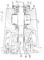
- FIG. 4A shows the vacuum pump housing 78 provided with two connections or ports 114, 116 located on opposite sides of the vacuum pump chamber 76 for introducing sealing liquid via ducts 118, 120 to both sides of the vacuum pump rotor 96 for sealing the clearance 122 between the vacuum pump rotor 96 including central portion and vanes and side walls 110, 112 of the eccentric vacuum chamber 76.
- the sealing liquid such as water
- the sealing liquid is fed at or around central portion 102 of vacuum pump rotor 96 so as to begin the portion closest to shaft 58.
- the sealing liquid thereafter carried outwardly by centrifugal forces during the operation of the vacuum pump.
- a first sealing liquid inlet port 114 is provided at the back side of the vacuum pump (in FIG. 4A the right hand side of the pump).
- Conduit 118 which extends substantially parallel to shaft 58 connects the vacuum pump chamber with liquid inlet port 114.
- the sealing liquid inlet into the vacuum pump chamber 76 through either one or both of the side walls of the vacuum pump is located in close proximity to the pump shaft 58 so that the sealing liquid will be supplied to the clearance 122 in the region of the central rotor portion 102 and the side wall 110, 112 of the vacuum pump housing 78.
- sealing liquid inlet port and conduit 116 is provided to extend through the vacuum pump housing 78 and intermediate wall 72.
- the sealing liquid is again supplied through conduit 116 directly to the front side of the vacuum pump and through a further channel (not shown) surrounding shaft 58 and which is preferably, but not necessarily circular, to the lower or suction side of the vacuum pump.
- sealing liquid will also seal the entire clearance between the radial length of the vanes 98 of the vacuum pump rotor and the side walls 110 and 112 of the vacuum chamber 76 as the centrifugal force acting on the sealing liquid together with the feed pressure will force the sealing liquid to slow along the vanes 98 in an outward direction.
- the sealing liquid is fed to both sides of the vacuum pump by using only one inlet port 124.
- the inlet port 124 is located in the vacuum pump housing adjacent the right hand side of the eccentric vacuum pump chamber 76. It is understood that the mentioned eccentricity is caused by the rotor being mounted at a position eccentric relative to the pump chamber as is necessary in liquid-ring pumps of the type described herein. Sealing liquid inlet port 124 is connected to conduit or duct 126 which guides the sealing liquid into the clearance 122 between the vacuum pump rotor 96 and the vacuum pump side wall 110.
- Conduit 126 leads from inlet portion 124 to a circular groove 128 within the vacuum pump rotor central portion 102 and through at least one throughbore 130 in said central portion 102 to preferably a record groove 132 at the opposite end of the vacuum pump rotor central portion 102.
- grooves 128 and optional groove 132 can also be located only in the vacuum pump chamber in the walls or may be provided in both the side walls and the rotor central portion as shown.
- mechanical sealing means may also be used such as, for example, gliding sealings or labyrinth seals.
- a circular grooves may also be provided in the embodiment described in FIG. 4A at the locations at which the sealing liquid enters the vacuum chamber at either one or both the vacuum chamber side walls and/or the rotor central portion 102.
- shaft 58 is mounted within pump frame 56 by suitable bearing units 51 and 55.
- the bearing unit 55 is slidably mounted and the bearing unit 51 is secured with a suitable locking means such as a lock unit 73 so that it will not slide along the shaft.
- a suitable locking means such as a lock unit 73
- the remainder of the pump is essentially the same as that described in connection with FIG. 2, above.
- vacuum pump rotor 96 with its center portion 102 and pump vanes 98 is fixedly secured to shaft 58 with the shoulder 105 of rotor 96 engaging a correspondingly shaped shoulder 104 of shaft 58.
- the axial position of the shaft can be adjusted by bolts 57 as follows.
- Bearing unit 51 is secured to slidable bearing support member 59 by, for example, a tong and groove arrangement (not shown) or any other suitable manner.
- Support member 59 has a bracket 61 which is provided with a threaded opening for receiving one or more adjusting bolts 57. Turning of bolts 57 will cause the shaft to move in a backward direction. Shaft 58 is kept in fixed position within bearing unit 51 and locking means 73.
- Adjusting and fixing bolt 77 extends through an opening in bracket 61 into threaded engagement with frame 56. Turning of adjusting bolts 57 and 77 permits the axial adjustment of shaft 58 in both directions and thus the precise positioning of the vacuum pump rotor 96 within vacuum pump chamber 76 allowing minimal clearances 108 between the rotor and the vacuum pump side walls.
- FIG. 6 shows a partial cross-sectional view of the centrifugal pump housing 50 and intermediate wall 72 separating the centrifugal pump chamber from the vacuum pump chamber 76.
- the intermediate wall 72 also frequently called “air head” or simply “head” has a central portion with an open volume 90 therein which is in communication with the vacuum pump chamber 76 and volute 54 through suitable openings 74 and 94.
- the vacuum pump housing 78 is fastened to intermediate wall or head 72 by bolts 63.
- One or more bolts 65 threadedly engage in pump frame 56 and one or more bolts 75 threadedly engage vacuum pump housing 78.
- the vacuum pump housing 78 and the fixedly secured head 72 are retained in place relative to the frame 76 by the one or more adjusting bolts 65 and 75 which permit the movement of the vacuum pump housing together with head 72 in axial direction relative to the shaft 58 so that the vacuum pump rotor 96 can be arranged within the vacuum pump chamber with minimal clearances 108 between the vacuum pump rotor 96 and its vanes 98 and the vacuum pump side walls 110 and 112.
- the rotor 96 is fixed on shaft 58 with mutually engaging shoulders 104, 105 as described above.
- the vacuum pump housing 78 and intermediate plate or head 72 can be adjusted relative to each other so that the width B and thereby the clearance 108 between the vacuum pump rotor and the vacuum pump side walls are optimized.
- the vacuum pump housing 78 and head 72 are mounted on a protrusion of frame 56 containing an opening for receiving one or more bolts 57 which threadedly engage with head 72.
- Width B between the vacuum pump housing rear wall 110 and head 72 can be adjusted by turning of one or more adjusting screws 69, 79 whereby screw 69 pulls head 72 toward vacuum pump housing 78; white turning of screw 79 move its head away therefrom.
- Frame 56 is secured to pump housing 50 in known manner.
- FIG. 8 shows a vacuum pump rotor 96 which is arranged on pump shaft 58 at a distance from the bearing unit (not shown).
- the shaft 58 tends to bend slightly during operation of the pump and, consequently, the clearance 134 between the vacuum pump rotor vanes 98 and the end walls 110, 112 of the vacuum chamber 76 will change so that there is a real risk of mechanical contact between the vanes 136 and the end walls 110, 112 causing extensive wear or even serious damage to the vacuum pump 70 in relatively short time.
- the axial length of the vanes 98 at the respective tips of the vanes is shorter than the axial length thereof at or close to the central portion 102 of the vacuum pump rotor 96. In other words, the clearance 134 decreases in the direction from the tips of the vanes 136 toward the shaft 58.
- FIG. 9 shows yet another embodiment and solution to the shaft bending problem.
- vacuum pump vanes 98 have equal axial length however, the axial dimension of the eccentric vacuum chamber 138 increases towards the outer circumference or surface 100 of the chamber 138 so that the amount of clearance 134 increases in radial direction in the same way as in the embodiment shown in FIG. 8. Accordingly, the axial distance B1 of the vacuum pump chamber 76 is smaller in the area surrounding the shaft than the distance B2 between the vacuum pump chamber side walls at the eccentric surface 100.
- the decrease in width of the vacuum pump rotor blades can be linear, stepped, curved or any combination thereof.
- the vacuum pump chamber side walls may tape radially outwardly in linear fashion, stepped, curved or in any combination thereof. It is also understood that both the vanes and the vacuum pump side walls may tape in radially outward direction in the same or similar manner.
Landscapes
- Engineering & Computer Science (AREA)
- Mechanical Engineering (AREA)
- General Engineering & Computer Science (AREA)
- Applications Or Details Of Rotary Compressors (AREA)
- Centrifugal Separators (AREA)
- Paper (AREA)
Applications Claiming Priority (2)
| Application Number | Priority Date | Filing Date | Title |
|---|---|---|---|
| US07/579,405 US5151010A (en) | 1990-09-07 | 1990-09-07 | Combined centrifugal and vacuum pump |
| US579405 | 1990-09-07 |
Publications (3)
| Publication Number | Publication Date |
|---|---|
| EP0474478A2 true EP0474478A2 (de) | 1992-03-11 |
| EP0474478A3 EP0474478A3 (en) | 1992-04-22 |
| EP0474478B1 EP0474478B1 (de) | 1995-11-29 |
Family
ID=24316766
Family Applications (1)
| Application Number | Title | Priority Date | Filing Date |
|---|---|---|---|
| EP91308102A Expired - Lifetime EP0474478B1 (de) | 1990-09-07 | 1991-09-04 | Kombinierte Zentrifugal- und Vakuumpumpe |
Country Status (5)
| Country | Link |
|---|---|
| US (1) | US5151010A (de) |
| EP (1) | EP0474478B1 (de) |
| AT (1) | ATE130909T1 (de) |
| DE (1) | DE69114959T2 (de) |
| ES (1) | ES2080910T3 (de) |
Cited By (6)
| Publication number | Priority date | Publication date | Assignee | Title |
|---|---|---|---|---|
| WO1993011359A1 (en) * | 1991-12-03 | 1993-06-10 | Kamyr Aktiebolag | Pump with built-in vacuum pump |
| WO1999066209A1 (en) * | 1998-06-17 | 1999-12-23 | Valmet Fibertech Ab | Pulp pump |
| WO2000022303A1 (en) * | 1998-10-13 | 2000-04-20 | Valmet Fibertech Ab | Pulp pump |
| CN1080392C (zh) * | 1995-06-05 | 2002-03-06 | 苏舍泵有限公司 | 控制离心泵与真空泵的组合的方法及一种气体分离离心泵 |
| WO2002075047A1 (en) * | 2001-03-21 | 2002-09-26 | Metso Paper, Inc | Pumping device |
| WO2003014572A1 (en) | 2001-08-08 | 2003-02-20 | Metso Paper, Inc. | Pulp pump |
Families Citing this family (8)
| Publication number | Priority date | Publication date | Assignee | Title |
|---|---|---|---|---|
| US5023193A (en) * | 1986-07-16 | 1991-06-11 | National Semiconductor Corp. | Method for simultaneously fabricating bipolar and complementary field effect transistors using a minimal number of masks |
| US6120252A (en) * | 1995-12-27 | 2000-09-19 | Ahlstrom Machinery Corporation | Gas separation control in a centrifugal pump/vacuum pump |
| US6241481B1 (en) * | 1998-09-09 | 2001-06-05 | Chrysler Corporation | Water pump shaft seal assembly for in-line water and power steering pumps |
| US6582193B1 (en) | 2000-07-27 | 2003-06-24 | Daimler Chrysler Corp | Composite water and power steering pump assembly |
| CN100365288C (zh) * | 2005-10-14 | 2008-01-30 | 江苏大学 | 一种用于离心泵的背叶片结构 |
| AT510538B1 (de) * | 2010-09-27 | 2013-02-15 | Andritz Ag Maschf | Zentrifugalpumpe |
| EP3011186B1 (de) | 2013-06-21 | 2020-12-30 | Flow Control LLC. | Rückstandsentfernende laufradrückschaufel |
| RU2675537C1 (ru) | 2015-10-08 | 2018-12-19 | Зульцер Мэнэджмент Аг | Способ и устройство для обработки биомассы |
Family Cites Families (3)
| Publication number | Priority date | Publication date | Assignee | Title |
|---|---|---|---|---|
| FR852435A (fr) * | 1938-04-09 | 1940-02-01 | Burckhardt Ag Maschf | Pompe rotative à roue à ailettes, à anneau de liquide, pour milieux gazeux |
| US4776758A (en) * | 1987-07-06 | 1988-10-11 | Kamyr Ab | Combined fluidizing and vacuum pump |
| US4877368A (en) * | 1988-11-08 | 1989-10-31 | A. Ahlstrom Corporation | Fluidizing centrifugal pump |
-
1990
- 1990-09-07 US US07/579,405 patent/US5151010A/en not_active Expired - Lifetime
-
1991
- 1991-09-04 EP EP91308102A patent/EP0474478B1/de not_active Expired - Lifetime
- 1991-09-04 ES ES91308102T patent/ES2080910T3/es not_active Expired - Lifetime
- 1991-09-04 AT AT91308102T patent/ATE130909T1/de not_active IP Right Cessation
- 1991-09-04 DE DE69114959T patent/DE69114959T2/de not_active Expired - Lifetime
Cited By (8)
| Publication number | Priority date | Publication date | Assignee | Title |
|---|---|---|---|---|
| WO1993011359A1 (en) * | 1991-12-03 | 1993-06-10 | Kamyr Aktiebolag | Pump with built-in vacuum pump |
| CN1080392C (zh) * | 1995-06-05 | 2002-03-06 | 苏舍泵有限公司 | 控制离心泵与真空泵的组合的方法及一种气体分离离心泵 |
| WO1999066209A1 (en) * | 1998-06-17 | 1999-12-23 | Valmet Fibertech Ab | Pulp pump |
| US6450764B1 (en) | 1998-06-17 | 2002-09-17 | Valmet Fibertech Ab | Pulp pump |
| WO2000022303A1 (en) * | 1998-10-13 | 2000-04-20 | Valmet Fibertech Ab | Pulp pump |
| US6488468B1 (en) | 1998-10-13 | 2002-12-03 | Valmet Fibertech Ab | Pulp pump |
| WO2002075047A1 (en) * | 2001-03-21 | 2002-09-26 | Metso Paper, Inc | Pumping device |
| WO2003014572A1 (en) | 2001-08-08 | 2003-02-20 | Metso Paper, Inc. | Pulp pump |
Also Published As
| Publication number | Publication date |
|---|---|
| US5151010A (en) | 1992-09-29 |
| EP0474478B1 (de) | 1995-11-29 |
| DE69114959T2 (de) | 1996-04-18 |
| EP0474478A3 (en) | 1992-04-22 |
| ES2080910T3 (es) | 1996-02-16 |
| DE69114959D1 (de) | 1996-01-11 |
| ATE130909T1 (de) | 1995-12-15 |
Similar Documents
| Publication | Publication Date | Title |
|---|---|---|
| CA2013132C (en) | Pump for and method of separating gas from a fluid to be pumped | |
| US5151010A (en) | Combined centrifugal and vacuum pump | |
| EP0474476B1 (de) | Drehpumpe | |
| US5114310A (en) | Centrifugal pump with sealing means | |
| US4921400A (en) | Pump and a method of separating gas by such from a fluid to be pumped | |
| US5152663A (en) | Centrifugal pump | |
| US4776758A (en) | Combined fluidizing and vacuum pump | |
| US5116198A (en) | Centrifugal pumping apparatus | |
| US4793777A (en) | Centrifugal pump with auxiliary impeller operatively associated with a primary impeller to balance the forces on the opposite sides thereof | |
| CA2150293C (en) | Centrifugal pump | |
| CA1217173A (en) | Liquid ring vacuum pump for gaseous media | |
| US8444370B2 (en) | Impeller for pumps | |
| US5711789A (en) | Apparatus for pumping gas-containing fiber suspensions | |
| CA1081044A (en) | Centrifugal slurry pump and method | |
| CN103597217A (zh) | 低磨损浆料泵 | |
| US4224008A (en) | Volute slurry pump and throttle bushing therefor | |
| US5605442A (en) | Centrifugal pump for pumping fiber suspensions | |
| EP1088170B1 (de) | Pumpe für papierbrei | |
| US6488468B1 (en) | Pulp pump | |
| EP1415094B1 (de) | Zellstoffpumpe | |
| EP4116588A1 (de) | Mehrstufige kreiselpumpe mit rezirkulationspfad | |
| WO1993011359A1 (en) | Pump with built-in vacuum pump | |
| CN1063531A (zh) | 旋转泵 |
Legal Events
| Date | Code | Title | Description |
|---|---|---|---|
| PUAI | Public reference made under article 153(3) epc to a published international application that has entered the european phase |
Free format text: ORIGINAL CODE: 0009012 |
|
| PUAL | Search report despatched |
Free format text: ORIGINAL CODE: 0009013 |
|
| 17P | Request for examination filed |
Effective date: 19910924 |
|
| AK | Designated contracting states |
Kind code of ref document: A2 Designated state(s): AT DE ES FR GB SE |
|
| AK | Designated contracting states |
Kind code of ref document: A3 Designated state(s): AT DE ES FR GB SE |
|
| 17Q | First examination report despatched |
Effective date: 19930601 |
|
| GRAA | (expected) grant |
Free format text: ORIGINAL CODE: 0009210 |
|
| AK | Designated contracting states |
Kind code of ref document: B1 Designated state(s): AT DE ES FR GB SE |
|
| REF | Corresponds to: |
Ref document number: 130909 Country of ref document: AT Date of ref document: 19951215 Kind code of ref document: T |
|
| REF | Corresponds to: |
Ref document number: 69114959 Country of ref document: DE Date of ref document: 19960111 |
|
| ET | Fr: translation filed | ||
| REG | Reference to a national code |
Ref country code: ES Ref legal event code: FG2A Ref document number: 2080910 Country of ref document: ES Kind code of ref document: T3 |
|
| PLBQ | Unpublished change to opponent data |
Free format text: ORIGINAL CODE: EPIDOS OPPO |
|
| PLBI | Opposition filed |
Free format text: ORIGINAL CODE: 0009260 |
|
| 26 | Opposition filed |
Opponent name: KVAERNER PULPING TECHNOLOGIES AB Effective date: 19960701 |
|
| PLBF | Reply of patent proprietor to notice(s) of opposition |
Free format text: ORIGINAL CODE: EPIDOS OBSO |
|
| PLBF | Reply of patent proprietor to notice(s) of opposition |
Free format text: ORIGINAL CODE: EPIDOS OBSO |
|
| PLBF | Reply of patent proprietor to notice(s) of opposition |
Free format text: ORIGINAL CODE: EPIDOS OBSO |
|
| PLBF | Reply of patent proprietor to notice(s) of opposition |
Free format text: ORIGINAL CODE: EPIDOS OBSO |
|
| PLBO | Opposition rejected |
Free format text: ORIGINAL CODE: EPIDOS REJO |
|
| PLBN | Opposition rejected |
Free format text: ORIGINAL CODE: 0009273 |
|
| STAA | Information on the status of an ep patent application or granted ep patent |
Free format text: STATUS: OPPOSITION REJECTED |
|
| 27O | Opposition rejected |
Effective date: 19980710 |
|
| REG | Reference to a national code |
Ref country code: GB Ref legal event code: 732E |
|
| REG | Reference to a national code |
Ref country code: GB Ref legal event code: IF02 |
|
| REG | Reference to a national code |
Ref country code: FR Ref legal event code: TP |
|
| PGFP | Annual fee paid to national office [announced via postgrant information from national office to epo] |
Ref country code: ES Payment date: 20090922 Year of fee payment: 19 |
|
| PGFP | Annual fee paid to national office [announced via postgrant information from national office to epo] |
Ref country code: GB Payment date: 20090922 Year of fee payment: 19 |
|
| PGFP | Annual fee paid to national office [announced via postgrant information from national office to epo] |
Ref country code: DE Payment date: 20090922 Year of fee payment: 19 |
|
| PGFP | Annual fee paid to national office [announced via postgrant information from national office to epo] |
Ref country code: SE Payment date: 20100914 Year of fee payment: 20 Ref country code: AT Payment date: 20100914 Year of fee payment: 20 |
|
| GBPC | Gb: european patent ceased through non-payment of renewal fee |
Effective date: 20100904 |
|
| REG | Reference to a national code |
Ref country code: FR Ref legal event code: ST Effective date: 20110531 |
|
| REG | Reference to a national code |
Ref country code: DE Ref legal event code: R119 Ref document number: 69114959 Country of ref document: DE Effective date: 20110401 |
|
| PG25 | Lapsed in a contracting state [announced via postgrant information from national office to epo] |
Ref country code: DE Free format text: LAPSE BECAUSE OF NON-PAYMENT OF DUE FEES Effective date: 20110401 Ref country code: FR Free format text: LAPSE BECAUSE OF NON-PAYMENT OF DUE FEES Effective date: 20100930 |
|
| PG25 | Lapsed in a contracting state [announced via postgrant information from national office to epo] |
Ref country code: GB Free format text: LAPSE BECAUSE OF NON-PAYMENT OF DUE FEES Effective date: 20100904 |
|
| PGFP | Annual fee paid to national office [announced via postgrant information from national office to epo] |
Ref country code: FR Payment date: 20091001 Year of fee payment: 19 |
|
| REG | Reference to a national code |
Ref country code: SE Ref legal event code: EUG |
|
| REG | Reference to a national code |
Ref country code: ES Ref legal event code: FD2A Effective date: 20111118 |
|
| PG25 | Lapsed in a contracting state [announced via postgrant information from national office to epo] |
Ref country code: ES Free format text: LAPSE BECAUSE OF NON-PAYMENT OF DUE FEES Effective date: 20100905 |