EP0474632B1 - Temperaturkontrolle in der flash-spinnzellenatmosphäre - Google Patents
Temperaturkontrolle in der flash-spinnzellenatmosphäre Download PDFInfo
- Publication number
- EP0474632B1 EP0474632B1 EP89911188A EP89911188A EP0474632B1 EP 0474632 B1 EP0474632 B1 EP 0474632B1 EP 89911188 A EP89911188 A EP 89911188A EP 89911188 A EP89911188 A EP 89911188A EP 0474632 B1 EP0474632 B1 EP 0474632B1
- Authority
- EP
- European Patent Office
- Prior art keywords
- spin
- cell
- temperature
- solvent
- spin cell
- Prior art date
- Legal status (The legal status is an assumption and is not a legal conclusion. Google has not performed a legal analysis and makes no representation as to the accuracy of the status listed.)
- Expired - Lifetime
Links
Images


Classifications
-
- D—TEXTILES; PAPER
- D01—NATURAL OR MAN-MADE THREADS OR FIBRES; SPINNING
- D01D—MECHANICAL METHODS OR APPARATUS IN THE MANUFACTURE OF ARTIFICIAL FILAMENTS, THREADS, FIBRES, BRISTLES OR RIBBONS
- D01D5/00—Formation of filaments, threads, or the like
- D01D5/11—Flash-spinning
Definitions
- the present invention relates to a process according to the preamble of claim 1 and known from US-A-3 504 076 for producing nonwoven webs of plexifilamentary strand material wherein the atmosphere of the spin-cell used to produce the nonwoven web is maintained within a narrow temperature range which is at least about 60°C below the melting point of the polymer forming the plexifilamentary strand material.
- the apparatus also utilizes a special resistor target plate and a special resistive coating on the apparatus extending partway between the electrostatic charging zone and the spin cell collection belt.
- Plexifilamentary strands are described by Blades and White in U.S. Patent No. 3,081,519.
- Each is a yarn-like strand having a surface-area greater than 2 m2/gm and comprising a continuous three-dimensional integral plexus of synthetic organic, crystalline, polymeric, fibrous elements.
- Said elements are structurally configured as oriented, film-fibrils with average film-thickness of less than 4 microns and with an average electron diffraction orientation angle of less than 90 degrees.
- a preferred class of suitable polymers for preparing plexifilamentary strands includes linear and branched chain polyethylene, polypropylene, copolymers of olefins, etc.; but other crystalline polymers such as polyethylene terephthalate and copolymers of ethylene with other monomers can be employed.
- a particularly preferred polymer is homopolymeric linear polyethylene with an upper limit to the melting range of from about 130-135°C, a density between 0.94 and 0.98 gm/cc, and a melt index (ASTM Test Method D-1238-57T, condition E) of 0.1 to 6.0.
- a process by which plexifilamentary strands may be obtained is given in U.S. Patent No. 3,227,784 to Blades and White, and with more particularly in U.S. Patent No. 3,227,794 to Anderson and Romano.
- the method generally comprises: (1) preparing a uniform solution of polymer in a solvent, said solution being at a temperature at least as high as (T c -45)°C, wherein T c is the solvent critical temperature, and at a sufficiently high pressure to maintain the solution as a single liquid phase; and (2) extruding said solution into a region of substantially reduced pressure and temperature where the solvent evaporates almost instantaneously and cools the polymeric material during the adiabatic expansion to form solidified plexifilamentary strand.
- US-A-3 504 076 discloses a process wherein a polymer and solvent composition is flash spun from one or more flash spinning dies onto a moving collection support in a spin-cell and a solvent is sprayed from nozzles into the spin cell to control the temperature of the spin-cell.
- Plexifilamentary strands are particularly useful in preparing nonwoven fibrous sheets as described in U.S. Patent No. 3,169,899 to Steuber.
- the extruded material passes horizontally from the extrusion orifice directly to the surface of a rotating or oscillating deflector which opens the plexifilament into a wide network and directs it downward onto a moving belt (or other surface) where it is collected in random, multidirectional, overlapping layers.
- Apparatus is also provided to create opposite electrostatic charges on the strands and collection belt.
- the apparatus also includes a special resistor target plate as the collector of the electrostatic charging current and a special resistive coating on the apparatus surface extending partway between the electrostatic charging zone and the spin cell collection belt.
- the solvents used in this process have normal boiling points at least about 25°C (preferably 60°C or more) below the polymer's melting temperature, are nonsolvents at or below their normal boiling points, and are usually haloalkanes.
- Trichlorofluoromethane and methylene chloride are frequently employed at levels of from about 80 to about 90% by weight of the polymer solution. Since these large quantities of solvent form no part of the ultimate sheet product, it is economically desirable that they be reclaimed and reused. This is accomplished by extruding the solution into a closed spin-cell which also contains the sheet-forming apparatus. The atmosphere in such a spin-cell is resultantly substantially 100% solvent vapor, and the solvent is readily reclaimed by withdrawing the vapor and condensing it to a liquid.
- Sheets with excellent properties are prepared by extrusion into and collection within the ambient atmosphere, without regard for solvent reclamation.
- Extrusion into a closed spin-cell containing an atmosphere substantially 100% of vaporized solvent at a spontaneously generated temperature surprisingly results in lowered sheet opacities, lowered delamination resistance, and variations in these properties across the width of the sheet when wide sheets of overlapping plexifilaments are prepared.
- This invention is an improvement in a process for producing nonwoven plexifilamentary webs comprising: (1) extruding a polymer solution through at least one orifice into a gaseous atmosphere of a closed spin-cell which is held at substantially normal atmospheric pressure, (2) collecting the resulting material on a moving conveyor within the spin-cell, to form a continuous web of random, multidirectional, overlapping layers and (3) withdrawing the web from the closed spin-cell.
- the improvement in the present process is controlling the temperature within the spin cell to within a narrow temperature range (48° to 52°C) by measuring the temperature of the gas in the exhaust port with a thermocouple and adjusting the feed rate of low boiling liquid to the spray nozzles in the spin cell in response to this temperature measurement. It has been found that this narrow range of temperature control is required for proper electrostatic performance of the process.
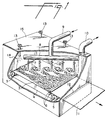
- FIG. 1 is a schematic of the cell indicating the temperature measuring points, the spray nozzle locations, and the pack locations relative to the nozzles and temperature measuring points.
- FIG. 2 is a cross section of the extrusion die and spin apparatus.
- FIG. 3 is a typical process schematic for spray nozzle system.
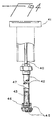
- FIG. 4 includes a cutaway of a typical spray nozzle used in cell cooling.
- a preferred method for preparing random webs of plexifilaments is initiated by forcing hot pressurized polymer solution into the apparatus of FIG. 1 via transfer line 9 and distributing it to the down-leg 16 of each extrusion position by a suitable manifold 8. At least one valve 7 is ordinarily provided in each down-leg 16. Extrusion of the solution through a plurality of die-assemblies 1 produces a plexifilament 2 which is opened, transversely oscillated, and directed downward onto a moving endless collection belt 4 driven by rolls 5.
- the plexifilament 2 forms a loose web 3 of random, multidirectional, overlapping layers which can be made wider by the proper lateral spacing of the plurality of die assemblies 1.
- FIG. 1 Not represented in FIG. 1 are drive means for rolls 5 and 6, but suitable direct or indirect sources of power are well known in the art. Likewise omitted for clarity are apparatus for solution preparation, apparatus for solvent reclamation, and means for heating transfer line 9, manifold 8, down-legs 16, and die assemblies 1.
- each die assembly can employ a single extrusion orifice
- a preferred die is of the type shown in FIG. 2 wherein two orifices 27 and 29 in series provide a pressure let-down zone 28 therebetween.
- a single liquid phase solution enters via down-leg 16.
- At least one low-pressure drop filter 25 is provided to prevent passage of accidental impurities capable of plugging let-down orifice 29 or spinneret-orifice 27. Passage of solution through let-down orifice 29 into let-down zone 28 causes a sharp pressure decrease resulting in formation of a two liquid phase solution within let-down zone 28. Finely divided droplets of a solvent-rich phase become distributed throughout the polymer-rich phase, but residence times are too short to permit coalescence of the droplets.
- Pressure sensor 20 provides for remote control of the critical pressure in let-down zone 28. From let-down zone 28, the solution passes through spinneret-orifice 27 into the atmosphere of spin-cell 15 (FIG. 1) which is usually held near atmospheric pressure. Almost instantaneously nearly all of the solvent vaporizes and the polymer solidifies to a plexifilament.
- a tunnel 26 is preferably provided for directing the plexifilament along the axial path of the orifice.
- the plexifilament 31 then impinges against a device, e.g., rotating disc 23, which is designed to open up the plexifilament, to direct it generally downward, and to oscillate it transversely about the straight downward direction.
- a rotating, electrically grounded, annular target plate 22 is mounted coaxially with disc 23 and additionally mounted so that the plexifilament 31 passes smoothly from the disc 23 over the surface of target-plate 22.
- Mounted oppositely from the plexifilament 31 is an ion gun 21 which, in cooperation with target plate 22, produces an electric charge on the plexifilament 31. Provision for oppositely charging the endless belt 4 of FIG. 1 is also made, but not shown.
- the die assembly 1 also includes driving means for selectively rotating disc 23 and target plate 22 at differing rates about axis 24.
- Target plate 22 and shields 32 and 36 are provided with special resistant coatings 33 and 34.
- each die assembly 1 all the functions described for each die assembly 1, plus die heating means and optional additional pressure and temperature sensors, are preferably provided in a single, integral assembly.
- the width of the portion of web 3 provided from each die assembly 1 is sufficently narrow as compared with the size of each assembly 1 that, when a plurality of die assemblies 1 is laterally spaced to provide a wider uniform sheet, they must ordinarily be spaced along the direction of motion of web 3 in order to accommodate their physical sizes.
- FIG. 3 diagramatically depicts a typical layout of the spray system showing the pump, tank, line, and nozzle general location.
- the pump needs to provide sufficient pressure so that the solvent sprays out of the nozzle, and this pressure/flow is generally specified by the type of nozzle used.
- the solvent such as trichlorofluoromethane, is contained in storage tank 30 and pumped by centrifugal pump 31' through filter 32'.
- An input signal from the thermocouple 17 in the exhaust port of the spin cell 38 is fed to controller 34' which activates control valve 35 to control the rate at which solvent is fed to spray nozzles 37 in spin cell 38.
- FIG. 4 is a cutaway of the cooling spray nozzle used in the present invention. Specific orifice size, number and location of spray nozzles is specified depending on the amount of cooling needed. The cooling is then adjusted, within limits, by varying the pressure (and thus the flow) of the solvent spraying from the nozzles, or adding or deleting nozzles or nozzle banks.
- the nozzle has a feed pipe 40, connected to the top of the cell deck 41, a removable length of pipe 42 fitted with strainer 43 and a plurality of spray nozzles 45 mounted on turret 46 which nozzles are in communication with the interior 47 of removable pipe 42.
- sheet visual quality is determined by backlighting the sheet and observing the sheet for light and dark areas and/or mottle (light and dark blotch areas), amount of rope or swirl or dark fibrous streaks caused by web collapsing or rolling on itself, and overall sheet transparency or opacity.
- good pack operation is determined by (1) minimal sudden pack failures due to electrostatic causes (spin pack plug or loss of web charge), and (2) a minimal loss of charging efficiency with time (charging efficiency is spun web current [electrostatic charge picked up by the web as it passes thorugh a charging zone defined by a charge emitter (Wand) and a collector of the current (Target Plate)] divided by wand current). Poor packs fail more frequently as a result of sudden pack failures, and the charging efficiency drops off with time more rapidly than with good packs.
- the smear is due to a low melt point component of the target plate deposits which melt with the higher temperature and/or the ability of very small particles to fuse/melt at the higher temperatures.
- the use of alternative polymers or solvents may well result in a different temperature range.
- thermocouples laocated in the spin cell atmosphere close to the spin cell ceiling near and about 45.7 cm (18") above the spin orifice
- thermocouples located in the spin cell return gas or exhaust port The cell temperature near the ceiling is taken to be representative of the cell gas "seen” by the spin pack since the spun gas/web issuing from the spin orifice of the spin pack aspirates significant amounts of cell gas and sweeps this gas through the spin packs.
- the target plate temperature when measured and compared to the cell gas temperature near the ceiling, is from 10° to 15°C higher than the cell gas.
- the temperature of the gas exiting the spin cell is normally 5°C cooler than the ceiling.
- the cell gas temperature is monitored using the exit gas temperature and applying the offset (5°C in this case).
- the temperature of the cell is controlled using nozzles which spray solvent into the cell atmosphere, the rate of cooling being directly proportional to the flow of solvent to the spray nozzles.
- the cooling nozzles are mainly orifices which allow the supplied solvent to be atomized into the warm spin cell atmosphere and cool it to the 48°-52°C range vs the uncooled range of 70°-100°C, dependent of cell insulation, solvent/polymer conditions, etc.
- the nozzles have 28 mil (7.1 x 10 ⁇ 4m) spin orifices.
- the nozzles are aimed so as to minimize the possibility of spray hitting a solid surface prior to all of the atomized droplets vaporizing. Spraying on a solid object results in the droplets combining into large drops and dripping rather than vaporizing.
- the nozzles are equally split on each side of the spin cell and the majority are located outside the spin pack grouping.
Landscapes
- Engineering & Computer Science (AREA)
- Mechanical Engineering (AREA)
- Textile Engineering (AREA)
- Spinning Methods And Devices For Manufacturing Artificial Fibers (AREA)
- Artificial Filaments (AREA)
- Nonwoven Fabrics (AREA)
Claims (2)
- Verfahren, worin eine Zusammensetzung aus einem Polymer und einem Lösungsmittel aus einer oder aus mehreren Flash-Spinndüsen (1) auf ein laufendes Sammelband (4) in einer Spinnzelle (15) flashgesponnen wird und ein Lösungsmittel aus Düsen (37) in die Spinnzelle gesprüht wird, um die Temperatur in der Spinnzelle zu regeln, dadurch gekennzeichnet, daß die Temperatur des Gases in dem aus der Spinnzelle (15) führenden Abgasrohr (10) gemessen wird und diese Messung dazu dient, die Zuführgeschwindigkeit zu regeln, mit der das Lösungsmittel zu den Sprühdüsen (37, 45) geführt wird, wodurch die Temperatur innerhalb von 2 °C von einem vorbestimmten Wert gehalten wird.
- Verfahren nach Anspruch 1, worin das Polymer ein Polyethylen von hoher Dichte ist, das Lösungsmittel Trichlorfluormethan ist und die Temperatur in der Spinnzelle auf 48 °C bis 52 °C gehalten wird.
Applications Claiming Priority (1)
| Application Number | Priority Date | Filing Date | Title |
|---|---|---|---|
| PCT/US1989/002191 WO1990015173A1 (en) | 1989-06-01 | 1989-06-01 | Control of flash spinning cell atmosphere temperature |
Publications (3)
| Publication Number | Publication Date |
|---|---|
| EP0474632A1 EP0474632A1 (de) | 1992-03-18 |
| EP0474632A4 EP0474632A4 (en) | 1993-01-27 |
| EP0474632B1 true EP0474632B1 (de) | 1995-05-03 |
Family
ID=22215031
Family Applications (1)
| Application Number | Title | Priority Date | Filing Date |
|---|---|---|---|
| EP89911188A Expired - Lifetime EP0474632B1 (de) | 1989-06-01 | 1989-06-01 | Temperaturkontrolle in der flash-spinnzellenatmosphäre |
Country Status (3)
| Country | Link |
|---|---|
| EP (1) | EP0474632B1 (de) |
| JP (1) | JPH04506384A (de) |
| WO (1) | WO1990015173A1 (de) |
Families Citing this family (3)
| Publication number | Priority date | Publication date | Assignee | Title |
|---|---|---|---|---|
| KR102939953B1 (ko) * | 2023-08-22 | 2026-03-17 | (주)씨앤투스 | 플래시 방사 장치에서 배출되는 용매의 회수 방법 |
| KR102900447B1 (ko) * | 2023-08-22 | 2025-12-16 | (주)씨앤투스 | 플래시 방사 장치에서 배출되는 용매의 회수 장치 |
| CN117661127A (zh) * | 2023-12-06 | 2024-03-08 | 优聚管理咨询(宁波)合伙企业(有限合伙) | 一种微纳米无纺布的制备方法及应用该方法获得的无纺布 |
Family Cites Families (6)
| Publication number | Priority date | Publication date | Assignee | Title |
|---|---|---|---|---|
| NL271149A (de) * | 1960-11-08 | 1900-01-01 | ||
| US3081519A (en) * | 1962-01-31 | 1963-03-19 | Fibrillated strand | |
| NL300881A (de) * | 1962-11-23 | |||
| US3504076A (en) * | 1967-04-06 | 1970-03-31 | Du Pont | Cooling of flash spinning cell atmosphere |
| BE795841A (fr) * | 1972-02-25 | 1973-08-23 | Montedison Spa | Procede de preparation de fibres a partir de matieres polymeres, convenant a la preparation de pulpe de papier |
| JPS5952882B2 (ja) * | 1979-11-02 | 1984-12-21 | 株式会社日立製作所 | スチレン系樹脂の連続塊状重合方法 |
-
1989
- 1989-06-01 JP JP1510430A patent/JPH04506384A/ja active Pending
- 1989-06-01 EP EP89911188A patent/EP0474632B1/de not_active Expired - Lifetime
- 1989-06-01 WO PCT/US1989/002191 patent/WO1990015173A1/en not_active Ceased
Also Published As
| Publication number | Publication date |
|---|---|
| WO1990015173A1 (en) | 1990-12-13 |
| EP0474632A4 (en) | 1993-01-27 |
| EP0474632A1 (de) | 1992-03-18 |
| JPH04506384A (ja) | 1992-11-05 |
Similar Documents
| Publication | Publication Date | Title |
|---|---|---|
| US4261943A (en) | Process for surface treating cellulose products | |
| US9834865B2 (en) | Centrifugal solution spun nanofiber process | |
| CA1135918A (en) | Process for surface treating cellulose products | |
| EP1656474B1 (de) | Drehverfahren zur herstellung eines einheitlichen materials | |
| EP1999304B2 (de) | Spun-faserlösungsverfahren | |
| US5476824A (en) | Process for preparing polymerization catalyst carrier by spray crystallization in an electric field | |
| EP0907770B1 (de) | Spinndüse zum flash-spinnen | |
| US3593074A (en) | Apparatus and process | |
| DE3708168C2 (de) | ||
| US3277526A (en) | Flash spinning apparatus | |
| US3787265A (en) | Process and apparatus for producing fibrous structures | |
| EP0828886B1 (de) | Gerät und verfahren zur herstellung einer faserstoffbahn | |
| EP0474632B1 (de) | Temperaturkontrolle in der flash-spinnzellenatmosphäre | |
| US3504076A (en) | Cooling of flash spinning cell atmosphere | |
| US4010229A (en) | Process for the manufacture of short fibrils | |
| US5098452A (en) | Method for controlling the level of solvent vapor in a vessel | |
| KR100756893B1 (ko) | 전기방사 장치 | |
| JPH03137209A (ja) | 合成繊維の紡糸冷却方法及び装置 | |
| CN107794580A (zh) | 一种高效溶体纺丝机 | |
| EP0472518B1 (de) | Anfahrmethode für flash-spinnverfahren unter verwendung eines unteren und oberen führungsblattes | |
| KR800000149B1 (ko) | 부직포 웨브의 제조방법 | |
| JP3618895B2 (ja) | 長繊維ウェブの製造方法 | |
| JPH0772388B2 (ja) | 不織ウエブ用の回転分散板 | |
| JPH11200220A (ja) | 不織布の製造方法 |
Legal Events
| Date | Code | Title | Description |
|---|---|---|---|
| PUAI | Public reference made under article 153(3) epc to a published international application that has entered the european phase |
Free format text: ORIGINAL CODE: 0009012 |
|
| AK | Designated contracting states |
Kind code of ref document: A1 Designated state(s): GB LU |
|
| 17P | Request for examination filed |
Effective date: 19911204 |
|
| A4 | Supplementary search report drawn up and despatched |
Effective date: 19921204 |
|
| AK | Designated contracting states |
Kind code of ref document: A4 Designated state(s): GB LU |
|
| 17Q | First examination report despatched |
Effective date: 19940209 |
|
| GRAA | (expected) grant |
Free format text: ORIGINAL CODE: 0009210 |
|
| AK | Designated contracting states |
Kind code of ref document: B1 Designated state(s): GB LU |
|
| PG25 | Lapsed in a contracting state [announced via postgrant information from national office to epo] |
Ref country code: LU Free format text: LAPSE BECAUSE OF NON-PAYMENT OF DUE FEES Effective date: 19950630 |
|
| PLBE | No opposition filed within time limit |
Free format text: ORIGINAL CODE: 0009261 |
|
| STAA | Information on the status of an ep patent application or granted ep patent |
Free format text: STATUS: NO OPPOSITION FILED WITHIN TIME LIMIT |
|
| PGFP | Annual fee paid to national office [announced via postgrant information from national office to epo] |
Ref country code: GB Payment date: 19960404 Year of fee payment: 8 |
|
| 26N | No opposition filed | ||
| PG25 | Lapsed in a contracting state [announced via postgrant information from national office to epo] |
Ref country code: GB Effective date: 19970601 |
|
| GBPC | Gb: european patent ceased through non-payment of renewal fee |
Effective date: 19970601 |