EP0474872A1 - Hydraulisches betätigungsventil - Google Patents
Hydraulisches betätigungsventil Download PDFInfo
- Publication number
- EP0474872A1 EP0474872A1 EP91902768A EP91902768A EP0474872A1 EP 0474872 A1 EP0474872 A1 EP 0474872A1 EP 91902768 A EP91902768 A EP 91902768A EP 91902768 A EP91902768 A EP 91902768A EP 0474872 A1 EP0474872 A1 EP 0474872A1
- Authority
- EP
- European Patent Office
- Prior art keywords
- valve
- valve body
- port
- control valve
- hydraulic control
- Prior art date
- Legal status (The legal status is an assumption and is not a legal conclusion. Google has not performed a legal analysis and makes no representation as to the accuracy of the status listed.)
- Granted
Links
- 238000005266 casting Methods 0.000 claims abstract description 24
- 238000003754 machining Methods 0.000 claims abstract description 12
- 230000007935 neutral effect Effects 0.000 claims abstract description 11
- 238000010276 construction Methods 0.000 claims abstract description 8
- 230000002547 anomalous effect Effects 0.000 claims description 12
- 238000000034 method Methods 0.000 abstract 1
- 238000004519 manufacturing process Methods 0.000 description 2
- 230000000717 retained effect Effects 0.000 description 2
- 230000035939 shock Effects 0.000 description 2
- 238000007514 turning Methods 0.000 description 2
- 230000015572 biosynthetic process Effects 0.000 description 1
- 238000005516 engineering process Methods 0.000 description 1
Images






Classifications
-
- F—MECHANICAL ENGINEERING; LIGHTING; HEATING; WEAPONS; BLASTING
- F16—ENGINEERING ELEMENTS AND UNITS; GENERAL MEASURES FOR PRODUCING AND MAINTAINING EFFECTIVE FUNCTIONING OF MACHINES OR INSTALLATIONS; THERMAL INSULATION IN GENERAL
- F16K—VALVES; TAPS; COCKS; ACTUATING-FLOATS; DEVICES FOR VENTING OR AERATING
- F16K27/00—Construction of housing; Use of materials therefor
- F16K27/04—Construction of housing; Use of materials therefor of sliding valves
- F16K27/041—Construction of housing; Use of materials therefor of sliding valves cylindrical slide valves
-
- F—MECHANICAL ENGINEERING; LIGHTING; HEATING; WEAPONS; BLASTING
- F15—FLUID-PRESSURE ACTUATORS; HYDRAULICS OR PNEUMATICS IN GENERAL
- F15B—SYSTEMS ACTING BY MEANS OF FLUIDS IN GENERAL; FLUID-PRESSURE ACTUATORS, e.g. SERVOMOTORS; DETAILS OF FLUID-PRESSURE SYSTEMS, NOT OTHERWISE PROVIDED FOR
- F15B13/00—Details of servomotor systems ; Valves for servomotor systems
- F15B13/02—Fluid distribution or supply devices characterised by their adaptation to the control of servomotors
- F15B13/06—Fluid distribution or supply devices characterised by their adaptation to the control of servomotors for use with two or more servomotors
- F15B13/08—Assemblies of units, each for the control of a single servomotor only
-
- Y—GENERAL TAGGING OF NEW TECHNOLOGICAL DEVELOPMENTS; GENERAL TAGGING OF CROSS-SECTIONAL TECHNOLOGIES SPANNING OVER SEVERAL SECTIONS OF THE IPC; TECHNICAL SUBJECTS COVERED BY FORMER USPC CROSS-REFERENCE ART COLLECTIONS [XRACs] AND DIGESTS
- Y10—TECHNICAL SUBJECTS COVERED BY FORMER USPC
- Y10T—TECHNICAL SUBJECTS COVERED BY FORMER US CLASSIFICATION
- Y10T137/00—Fluid handling
- Y10T137/8593—Systems
- Y10T137/87169—Supply and exhaust
- Y10T137/87177—With bypass
- Y10T137/87185—Controlled by supply or exhaust valve
-
- Y—GENERAL TAGGING OF NEW TECHNOLOGICAL DEVELOPMENTS; GENERAL TAGGING OF CROSS-SECTIONAL TECHNOLOGIES SPANNING OVER SEVERAL SECTIONS OF THE IPC; TECHNICAL SUBJECTS COVERED BY FORMER USPC CROSS-REFERENCE ART COLLECTIONS [XRACs] AND DIGESTS
- Y10—TECHNICAL SUBJECTS COVERED BY FORMER USPC
- Y10T—TECHNICAL SUBJECTS COVERED BY FORMER US CLASSIFICATION
- Y10T137/00—Fluid handling
- Y10T137/8593—Systems
- Y10T137/87169—Supply and exhaust
- Y10T137/87233—Biased exhaust valve
- Y10T137/87241—Biased closed
Definitions
- the present invention relates to a hydraulic control valve adapted for use in a construction machine such as a power shovel.
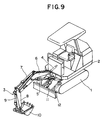
- a conventional power shovel comprises, as illustrated in Fig. 9, a lower self-propelled movable body 1 driven by a propelling motor, not shown, an upper turntable 2 capable of being turned by a turning motor, not shown, and a working machine 3 mounted at the front portion of the turntable 2.
- the working machine 3 has a boom 6 which can be swung rightward and leftward by a swinging cylinder 4 and movable vertically at the tip end thereof by a boom cylinder 5 and an arm 8 pivotally mounted at the tip end of the boom 6 which is turned by an arm cylinder 7.
- the arm 8 has a tip end to which a bucket 10 is attached so as to be turned by a bucket cylinder 9.
- a blade 12 which is vertically movable by a blade cylinder 11 is mounted at the front portion of the movable body 1.
- a hydraulic control valve 13 provided at each actuator controls the propelling motor, the turning motor and hydraulic actuators composed of various cylinders.
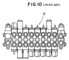
- Each hydraulic control valve 13 is, as illustrated in Fig. 10, normally connected with one another.
- Each hydraulic control valve 13 comprises, as illustrated in Fig. 11, a valve body 13a, a spool 14 housed in the valve body 13a for switching oil passages in the valve body 13a, the spool 14 normally retained at a neutral position by a return spring 13b wherein an oil under pressure supplied to a pump port 13c is drained through a drain port 13d into a tank 16 by way of a port block 15.
- the valve body 13a of the hydraulic control valve 13 is, as illustrated in Fig. 12, conventionally formed integrally by casting.
- a main core for forming a spool port 13h is complex so that nallow passages can not be formed in the hydraulic control valve 13 since a cylinder drain port 13e, a bridge port 13g and the spool port 13h are separately formed in three stages.
- the present invention has been made in view of the problem set forth above and is to provide a hydraulic control valve capable of manufacturing a valve body without using cores having complex structures.
- the conventional control valve body is, as described above, integrally formed by casting and a passage of a neutral port in a valve chamber is also formed by casting wherein cores are employed for forming the passage of the neutral port at the time of casting.
- the core is formed, as illustrated in Fig. 13, by casting a main core 19 for forming the spool port 13h and thereafter by jointing joint cores 20 and 21 to the main core 19.
- a mold can not be splitted along the line X-X when forming the core if the jointing cores 20 and 21 are integrated with each other, which involves the following drawbacks.
- the valve body 13a of the conventional control valve 13 forms therein, as illustrated in Fig. 14, a parallel port 13f, the bridge ports 13g, cylinder ports 13i and the cylinder drain port 13e wherein a load check valve 17 for allowing the oil under pressure only to flow from the parallel port 13f into the bridge port 13g is provided between the parallel port 13f and the bridge port 13g and a hydraulic cylinder 18 is connected to the cylinder ports 13i therebetween.
- the oil under pressure introduced into the pump port 13c reaches the parallel port 13f and pushes the load check valve 17, then flows into the bridge ports 13g.
- the oil under pressure is further introduced into a bottom side of a hydraulic cylinder 18 from cylinder ports 13i which communicates with the spool 14 by the movement of the spool 14 so as to stretch the hydraulic cylinder 18 whereas the oil under pressure at the side of the cylinder rod flows from the cylinder ports 13i to the cylinder drain port 13e and thereafter drained into a tank 16.
- a suction safty valve 120 is conventionally provided, as illustrated in Fig. 15, between the cylinder ports 13i and the cylinder drain port 13e for preventing the anomalous pressure or the negative pressure from being generated.
- a poppet 121 provided inside the suction safty valve 120 is released so that the pressure inside the cylinder ports 13i is relieved into the cylinder drain port 13e to prevent the anomalous pressure from being generaed in the hydraulic circuit.
- a suction valve 122 is released by the negative pressure so that the oil under pressure in the tank 16 is introduced into the cylinder port 13i from the cylinder drain port 13e whereby the negative pressure is prevented from being generated in the hydraylic circuit.
- the conventional hydraulic control valve 13 has the suction safty valve 120 serving as the safty valve function and the suction valve function combined in a single valve so that the structure of the valve is complex which impedes the miniaturization thereof.
- the core for forming the passage of a neutral port of cores in a valve chamber is formed merely by the main core for forming a spool port and the passage portion which was conventionally formed by jointing cores which jointed to the main core can be formed by machining, thereby eliminating the jointing cores. Accordingly, a manual working step for jointing the jointing cores to the main core can be eliminated which improves the working efficiency and the casting accuracy by preventing the casting flash and porosity from occuring.
- valve body of the hydraulic control valve according to the present invention can relieve the anomalous pressure generated in the hydraulic circuit into the tank and has the safty valve for sucking the oil under pressure from the tank when the negative pressure is generated, that is, the safty valve for relieving the anomalous pressure and the suction valve for preventing the negative pressure are separately provided on the valve body and disposed apart on the valve body so that the structure of the valve body can be compact and minituarized.
- the hydraulic control valve can be minituarized as a whole.
- Fig. 1 is a lateral cross sectional view of a hydraulic control valve according to an embodiment of the present invention
- Fig. 2 is a vertical cross sectional view of the hydraulic control valve in Fig. 1
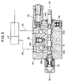
- Figs. 3 and 4 are view showing operations of the hydraulic control valve in Fig. 1
- Figs. 5(a) and 5(b) are views showing hydraulic control valves according to another embodiment of the present invention wherein a main core forming a spool port and the shape of casting are respectively explained illustratively which are cross sectional views taken along V-V in Fig. 12, Figs.
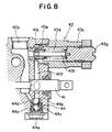
- FIG. 6 to 8 are a lateral cross sectional view, a longitudinal cross sectional view and an enlarged view showing a portion close to a safty valve and a suction valve according to still another embodiment of the present invention
- Fig. 9 is a perspective view of a construction machine which is an object to be controlled by the hydraulic control valve
- Fig. 10 is a plan view of a conventional hydraulic control valve
- Fig. 11 is a lateral cross sectional view of Fig. 10
- Fig. 12 is a cross sectional view of a valve body
- Fig. 13 is a cross sectional view explaining a main core for forming a spool port of the valve body of the conventional hydraulic control valve
- Fig. 14 is an enlarged vertical cross sectional view of the conventional hydraulic control valve
- Fig. 15 is an enlarged view of a suction safty valve of the conventional hydraulic control valve.
- valve body 40 is a valve body
- 41 is a spool slidably housed in a spool port 20a of the valve body 40
- 22 is a return spring for retaing the spool 41 at a neutral position
- 43 is a safty valve
- 44 is a suction valve
- 25 is a load check valve.
- the valve body 40 has a parallel port 20b and bridge ports 20c which are respetively formed by machining by way of a hole 20h to which a load check valve 25 is attached.
- the load check valve 25 is attached between the parallel port 20b and the bridge ports 20c for allowing an oil under pressure to flow merely from the parallel port 20b into the bridge ports 20c.
- Cylinder ports 20d are formed at both sides of the bridge ports 20c and connected to a bottom side of a hydraulic cylinder 27 and a rod side of the hydraulic cylinder 27 by way of lines 28.
- Cylinder drain ports 20e are provided as through holes at both sides of the cylinder ports 20d so as to penetrate both side surfaces of the valve body 40.
- a drain passage 30a in a tank port block 39 attached to the side surface of the valve body 40 is connected to the cylinder drain ports 20e.
- the drain passage 30a in the tank port block 39 is also connected to drain ports 20e of the valve body 40 so that the oil under pressure discharged from a pump port 20g to the drain ports 20e is drained into a tank 31 through the drain passage 30a when the spool is retained at the neutral position.
- the oil under pressure at the rod side of the hydraulic cylinder 27 is introduced into the cylinder drain ports 20e communicating with the cylinder ports 20d by the movement of the spool 21 and further flows into the drain passage 30a of the tank port block 39 as illustrated in Fig. 4 (a cross sectional view taken along IV-IV in Fig. 3), and is finally drained into the tank 31.
- the passage of the neutral port in the valve chamber is formed by casting and the core is used for forming this passage at the time of casting wherein the spool port 13h is formed by the main core 19.
- the embodiment of the present invention is characterized in that the passage portion of the neutral port, which was conventionally formed by jointing the joint cores 20 and 21 to the main core 19, can be formed by machining.
- the portions as denoted 20' and 21' in Fig. 5(b) are passage portions conventionally formed by the cores but they can be formed by machinig according to the present invention.
- the joint cores can be eliminated and the formation of the core can be composed of only the main core 19 as illustrated in Fig. 5(a) which solves the various drawbacks accompanied by the adoption of the conventional joint cores and improves the casting accuracy.
- Figs. 6 to 8 show still another embodiment of the present invention.
- valve body 40 is a valve body
- 41 is a spool movably provided in the valve body 40
- 42 is a return spring for retaining the spool 41 at the neutral position
- 43 is a safty valve
- 44 is a suction valve
- 45 is a load check valve.
- the valve body has therein a pump port 40a, a drain port 40b, a parallel port 40c, bridge ports 40d, cylinder ports 40e and cylinder drain ports 40f wherein a load check valve 45 is provided between the parallel port 40c and the bridge ports 40d for allowing the oil under pressure merely to flow from the parallel port 40c into the sides of the bridge ports 40d and the cylinder ports 40e connected to the bottom side and the rod side of a hydraulic cylinder 46 provided in the working machine by way of lines 47.
- a safety valve 43 and a suction valve 44 are respectively provided separately between the cylinder ports 40e and the cylinder drain ports 40f.
- the safety valve 43 as illustrated in Fig. 8, has one end which is screwed into an end surface of the valve body 40 and a valve seat 43c is provided midway on a passage communicating the cylinder port 40e and the cylinder drain port 40f.
- a poppet 43e which is biased by a poppet spring 43d, is pressed against the valve seat 43c.
- a piston 43f penetrates a central portion of the poppet 43e and another end of the piston 43f is fixedly mounted at an adjusting screw 43g screwed into another end of the case 43a.
- the suction valve 44 provided separately from the safety valve 43 blocks, as illustrated in Fig. 8, a valve hole 44a bored in the valve body 40 which communicates with the cylinder ports 40e and the cylinder drain ports 40f and a valve seat 44b defined at the opening of the cylinder drain ports 40f.
- a ball-shaped suction valve 44d is pressed against the valve seat 44b by a suction spring 44c while a plug 44e housing the suction spring 44c therein is screwed into the lower opening of the valve hole 44a.
- the oil under pressure at the rod side of the hydraulic cylinder 46 flows into the cylinder drain ports 40f communicating with the cylinder ports 40e by the movement of the spool 41 and thereafter drained into a tank 48.
- the hydraulic control valve according to this embodiment can be manufactured with ease and structured compact in size compared with the conventional hydraulic control valve which has the safety valve integrated with the suction valve. It is possible to make the valve body compact in size by separating the safety valve from the suction valve and incorporating them into the valve body.
- the parallel port and the bridge ports in the valve body are formed by machining and the jointing portions of the right and left cylinder drain ports are provided outside the valve body so that the ports formed in the valve body at the time of casting comprises only the spool port which can be formed by the main core.
- valve body can be casted with use of the single-stage core, a narrow spool port can be formed in the control valve, so that the spool having a diameter less than 10 mm can be manufactured with ease which facilitates the miniaturization thereof and reduction of weight thereof.
- the passage portion conventionally formed by the joint core jointed to the main core for forming the spool port can be formed by machining, it is possible to dispense with the joint cores so that the core is formed by only the main core. As a result, it is possible to automatically form the core assembly whereby the working efficiency can be improved conspicuously and the jointing deviation of the core and the casting flash at the jointing portion and the casting porosity due to the generation of the gas of the jointing agent can be respectively eliminated. As a result, the casting accuracy can be improved.
- the hydraulic control valve according to the present invention becomes compact in structure thereof and is manufactured with ease at a low cost compared with the conventional hydraulic control valve having the safety valve integrated with the suction valve.
- the safety valve and the suction valve are separately provided and the suction valve is incorporated into the valve body, the safety valve can be made compact in size which results in the miniaturization of the valve body of the hydraulic control valve.
Landscapes
- Engineering & Computer Science (AREA)
- General Engineering & Computer Science (AREA)
- Mechanical Engineering (AREA)
- Physics & Mathematics (AREA)
- Fluid Mechanics (AREA)
- Fluid-Pressure Circuits (AREA)
- Valve Housings (AREA)
Applications Claiming Priority (7)
| Application Number | Priority Date | Filing Date | Title |
|---|---|---|---|
| JP2051716A JPH03255203A (ja) | 1990-03-05 | 1990-03-05 | 油圧操作弁 |
| JP2051715A JPH083193B2 (ja) | 1990-03-05 | 1990-03-05 | 油圧操作弁 |
| JP51716/90 | 1990-03-05 | ||
| JP51715/90 | 1990-03-05 | ||
| JP64039/90 | 1990-03-16 | ||
| JP6403990A JPH03265772A (ja) | 1990-03-16 | 1990-03-16 | 油圧操作弁 |
| PCT/JP1991/000097 WO1991014121A1 (fr) | 1990-03-05 | 1991-01-29 | Soupape hydraulique de commande |
Publications (3)
| Publication Number | Publication Date |
|---|---|
| EP0474872A1 true EP0474872A1 (de) | 1992-03-18 |
| EP0474872A4 EP0474872A4 (en) | 1992-09-02 |
| EP0474872B1 EP0474872B1 (de) | 1995-08-30 |
Family
ID=27294410
Family Applications (1)
| Application Number | Title | Priority Date | Filing Date |
|---|---|---|---|
| EP19910902768 Expired - Lifetime EP0474872B1 (de) | 1990-03-05 | 1991-01-29 | Hydraulisches betätigungsventil |
Country Status (4)
| Country | Link |
|---|---|
| US (1) | US5394903A (de) |
| EP (1) | EP0474872B1 (de) |
| DE (1) | DE69112544T2 (de) |
| WO (1) | WO1991014121A1 (de) |
Cited By (1)
| Publication number | Priority date | Publication date | Assignee | Title |
|---|---|---|---|---|
| EP0708253A1 (de) * | 1994-09-29 | 1996-04-24 | Samsung Heavy Industries Co., Ltd | Ölablassvorrichtung für einen Kolbenschieberdeckel |
Families Citing this family (11)
| Publication number | Priority date | Publication date | Assignee | Title |
|---|---|---|---|---|
| DE19512007A1 (de) * | 1995-03-31 | 1996-10-02 | Rexroth Mannesmann Gmbh | Hydraulisch betätigbares Wegeventil |
| US6116143A (en) * | 1996-07-05 | 2000-09-12 | Parker Hannifin Gmbh | Controller for a fluid cylinder |
| US6135148A (en) * | 1998-11-30 | 2000-10-24 | Grabber Manufacturing Co., Ltd. | Air hydraulic remote control device |
| US6298881B1 (en) | 1999-03-16 | 2001-10-09 | Shigemoto & Annett Ii, Inc. | Modular fluid handling assembly and modular fluid handling units with double containment |
| RU2186263C2 (ru) * | 2000-09-12 | 2002-07-27 | Архипов Ростислав Семенович | Корпус золотникового гидрораспределителя |
| US6990999B2 (en) * | 2003-05-05 | 2006-01-31 | Kjp Investments Llc | Digitally controlled modular valve system |
| US8777545B2 (en) * | 2009-10-20 | 2014-07-15 | Bright Coop, Inc. | Free lift mast for truck mounted forklift |
| JP5602074B2 (ja) * | 2011-03-16 | 2014-10-08 | カヤバ工業株式会社 | 制御弁 |
| CN106232907B (zh) * | 2014-04-29 | 2018-11-02 | 沃尔沃建造设备有限公司 | 用于工程机械的流量控制阀 |
| US10323659B2 (en) | 2017-05-16 | 2019-06-18 | Parker-Hannifin Corporation | Open center control valve |
| CN110173474A (zh) * | 2019-05-05 | 2019-08-27 | 天津海弗液压技术有限公司 | 一种剪插车液压系统整体式阀块 |
Family Cites Families (20)
| Publication number | Priority date | Publication date | Assignee | Title |
|---|---|---|---|---|
| US3012576A (en) * | 1959-02-24 | 1961-12-12 | Commercial Shearing | Control valves with spool check and spool alignment devices |
| US3414017A (en) * | 1966-09-06 | 1968-12-03 | Commercial Shearing | Fluid control valves |
| US3502109A (en) * | 1967-12-07 | 1970-03-24 | Gresen Manufacturing Co | Quick response pilot operated valve |
| GB1340193A (en) * | 1970-04-24 | 1973-12-12 | Dowty Technical Dev Ltd | Selector valves |
| US3659325A (en) * | 1970-06-03 | 1972-05-02 | Cessna Aircraft Co | Control valve method of manufacture |
| US3717175A (en) * | 1971-04-08 | 1973-02-20 | Dowty Technical Dev Ltd | Selector valves |
| US4139021A (en) * | 1972-07-19 | 1979-02-13 | Cross Manufacturing, Inc. | Hydraulic control instrumentality |
| US3771558A (en) * | 1972-07-20 | 1973-11-13 | Cross Manuf Inc | Combined open-center pressure control and regeneration valve |
| DE2601484C2 (de) * | 1976-01-16 | 1984-07-26 | Robert Bosch Gmbh, 7000 Stuttgart | Steuereinrichtung für mindestens zwei von einer Druckmittelquelle gespeiste hydraulische Verbraucher |
| US4099541A (en) * | 1976-11-12 | 1978-07-11 | Sperry Rand Corporation | Power transmission |
| US4215720A (en) * | 1978-10-02 | 1980-08-05 | General Signal Corporation | Fluid control valve system |
| US4253482A (en) * | 1979-03-05 | 1981-03-03 | Gresen Manufacturing Company | Hydraulic valve having pressure compensated demand flow |
| JPS56139064U (de) * | 1980-03-22 | 1981-10-21 | ||
| JPS56139064A (en) * | 1980-03-31 | 1981-10-30 | Matsushita Electric Works Ltd | Rotor for flat motor |
| US4430927A (en) * | 1980-06-19 | 1984-02-14 | Rubery Owen (Hydraulics) Limited | Hydraulic valves |
| JPS58113604A (ja) * | 1981-12-25 | 1983-07-06 | Hitachi Constr Mach Co Ltd | 多連コントロ−ルバルブ |
| US4655250A (en) * | 1986-02-03 | 1987-04-07 | The Cessna Aircraft Company | Open center unloading valve |
| JPS6454588A (en) * | 1987-08-25 | 1989-03-02 | Nec Corp | Automatic paper money handler |
| JPH01169183A (ja) * | 1987-12-23 | 1989-07-04 | Koganei Seisakusho:Kk | マニホールド弁 |
| JPH0716943Y2 (ja) * | 1989-01-27 | 1995-04-19 | 東芝機械株式会社 | 方向制御弁 |
-
1991
- 1991-01-29 WO PCT/JP1991/000097 patent/WO1991014121A1/ja not_active Ceased
- 1991-01-29 EP EP19910902768 patent/EP0474872B1/de not_active Expired - Lifetime
- 1991-01-29 US US08/167,442 patent/US5394903A/en not_active Expired - Fee Related
- 1991-01-29 DE DE69112544T patent/DE69112544T2/de not_active Expired - Fee Related
Cited By (1)
| Publication number | Priority date | Publication date | Assignee | Title |
|---|---|---|---|---|
| EP0708253A1 (de) * | 1994-09-29 | 1996-04-24 | Samsung Heavy Industries Co., Ltd | Ölablassvorrichtung für einen Kolbenschieberdeckel |
Also Published As
| Publication number | Publication date |
|---|---|
| EP0474872B1 (de) | 1995-08-30 |
| WO1991014121A1 (fr) | 1991-09-19 |
| EP0474872A4 (en) | 1992-09-02 |
| DE69112544T2 (de) | 1996-02-08 |
| US5394903A (en) | 1995-03-07 |
| DE69112544D1 (de) | 1995-10-05 |
Similar Documents
| Publication | Publication Date | Title |
|---|---|---|
| US5394903A (en) | Hydraulic control valve | |
| US4757685A (en) | Pressure responsive hydraulic control circuit | |
| KR100379862B1 (ko) | 방향 전환 밸브 장치 | |
| JP3491771B2 (ja) | 圧力補償弁及び圧油供給装置 | |
| GB2313413A (en) | Variable-regeneration directional control valve for constructional vehicles | |
| KR100631067B1 (ko) | 홀딩밸브의 응답성이 개선된 유압제어밸브 | |
| JPH0716943Y2 (ja) | 方向制御弁 | |
| KR20030046752A (ko) | 굴삭기용 홀딩밸브장치 및 홀딩밸브의 유압제어방법 | |
| JPS5836203B2 (ja) | リユウタイセイギヨカイロ | |
| CN113544390A (zh) | 流量控制阀 | |
| US3746040A (en) | Directional control valve | |
| US5046400A (en) | Control valve system | |
| WO2020044701A1 (ja) | 流体圧制御装置 | |
| JP3494232B2 (ja) | 作動シリンダの制御装置 | |
| JPS62278302A (ja) | 可変再生回路 | |
| JPS642807B2 (de) | ||
| US12140162B2 (en) | Spool valve and hydraulic apparatus including the same | |
| US5755260A (en) | Mono-block control valve with regeneration conduit | |
| KR100468623B1 (ko) | 암재생용 스풀을 갖는 굴삭기 컨트롤밸브의 암 재생장치 | |
| JP2654953B2 (ja) | 2速モータの制御装置 | |
| JP2630775B2 (ja) | 高負荷アクチュエータの優先作動制御装置 | |
| GB1594268A (en) | Control valves | |
| JPS6212884Y2 (de) | ||
| JP4007675B2 (ja) | 自動切換弁装置 | |
| JPS6144005Y2 (de) |
Legal Events
| Date | Code | Title | Description |
|---|---|---|---|
| PUAI | Public reference made under article 153(3) epc to a published international application that has entered the european phase |
Free format text: ORIGINAL CODE: 0009012 |
|
| 17P | Request for examination filed |
Effective date: 19911028 |
|
| AK | Designated contracting states |
Kind code of ref document: A1 Designated state(s): DE FR GB IT SE |
|
| A4 | Supplementary search report drawn up and despatched |
Effective date: 19920713 |
|
| AK | Designated contracting states |
Kind code of ref document: A4 Designated state(s): DE FR GB IT SE |
|
| 17Q | First examination report despatched |
Effective date: 19931216 |
|
| GRAA | (expected) grant |
Free format text: ORIGINAL CODE: 0009210 |
|
| AK | Designated contracting states |
Kind code of ref document: B1 Designated state(s): DE FR GB IT SE |
|
| REF | Corresponds to: |
Ref document number: 69112544 Country of ref document: DE Date of ref document: 19951005 |
|
| ITF | It: translation for a ep patent filed | ||
| ET | Fr: translation filed | ||
| PLBE | No opposition filed within time limit |
Free format text: ORIGINAL CODE: 0009261 |
|
| STAA | Information on the status of an ep patent application or granted ep patent |
Free format text: STATUS: NO OPPOSITION FILED WITHIN TIME LIMIT |
|
| 26N | No opposition filed | ||
| REG | Reference to a national code |
Ref country code: FR Ref legal event code: CA |
|
| REG | Reference to a national code |
Ref country code: GB Ref legal event code: IF02 |
|
| PGFP | Annual fee paid to national office [announced via postgrant information from national office to epo] |
Ref country code: GB Payment date: 20040107 Year of fee payment: 14 |
|
| PGFP | Annual fee paid to national office [announced via postgrant information from national office to epo] |
Ref country code: FR Payment date: 20040120 Year of fee payment: 14 |
|
| PGFP | Annual fee paid to national office [announced via postgrant information from national office to epo] |
Ref country code: SE Payment date: 20040126 Year of fee payment: 14 |
|
| PGFP | Annual fee paid to national office [announced via postgrant information from national office to epo] |
Ref country code: DE Payment date: 20040130 Year of fee payment: 14 |
|
| PG25 | Lapsed in a contracting state [announced via postgrant information from national office to epo] |
Ref country code: IT Free format text: LAPSE BECAUSE OF NON-PAYMENT OF DUE FEES;WARNING: LAPSES OF ITALIAN PATENTS WITH EFFECTIVE DATE BEFORE 2007 MAY HAVE OCCURRED AT ANY TIME BEFORE 2007. THE CORRECT EFFECTIVE DATE MAY BE DIFFERENT FROM THE ONE RECORDED. Effective date: 20050129 Ref country code: GB Free format text: LAPSE BECAUSE OF NON-PAYMENT OF DUE FEES Effective date: 20050129 |
|
| PG25 | Lapsed in a contracting state [announced via postgrant information from national office to epo] |
Ref country code: SE Free format text: LAPSE BECAUSE OF NON-PAYMENT OF DUE FEES Effective date: 20050130 |
|
| PG25 | Lapsed in a contracting state [announced via postgrant information from national office to epo] |
Ref country code: DE Free format text: LAPSE BECAUSE OF NON-PAYMENT OF DUE FEES Effective date: 20050802 |
|
| EUG | Se: european patent has lapsed | ||
| GBPC | Gb: european patent ceased through non-payment of renewal fee |
Effective date: 20050129 |
|
| PG25 | Lapsed in a contracting state [announced via postgrant information from national office to epo] |
Ref country code: FR Free format text: LAPSE BECAUSE OF NON-PAYMENT OF DUE FEES Effective date: 20050930 |
|
| REG | Reference to a national code |
Ref country code: FR Ref legal event code: ST |