EP0474910B2 - Collier de serrage en croix ainsi que réseau de cables avec colliers de serrage en croix - Google Patents
Collier de serrage en croix ainsi que réseau de cables avec colliers de serrage en croix Download PDFInfo
- Publication number
- EP0474910B2 EP0474910B2 EP90117708A EP90117708A EP0474910B2 EP 0474910 B2 EP0474910 B2 EP 0474910B2 EP 90117708 A EP90117708 A EP 90117708A EP 90117708 A EP90117708 A EP 90117708A EP 0474910 B2 EP0474910 B2 EP 0474910B2
- Authority
- EP
- European Patent Office
- Prior art keywords
- cross
- clamp
- claws
- claw
- slots
- Prior art date
- Legal status (The legal status is an assumption and is not a legal conclusion. Google has not performed a legal analysis and makes no representation as to the accuracy of the status listed.)
- Expired - Lifetime
Links
- 210000000078 claw Anatomy 0.000 claims abstract description 52
- 238000003825 pressing Methods 0.000 claims description 6
- 239000002184 metal Substances 0.000 claims description 4
- 230000006835 compression Effects 0.000 abstract 1
- 238000007906 compression Methods 0.000 abstract 1
- 239000004575 stone Substances 0.000 description 14
- 238000004519 manufacturing process Methods 0.000 description 7
- 238000005452 bending Methods 0.000 description 5
- 238000006073 displacement reaction Methods 0.000 description 5
- 238000000034 method Methods 0.000 description 4
- 229910000831 Steel Inorganic materials 0.000 description 3
- 238000004080 punching Methods 0.000 description 3
- 239000010959 steel Substances 0.000 description 3
- 238000005266 casting Methods 0.000 description 1
- 238000005336 cracking Methods 0.000 description 1
- 230000000694 effects Effects 0.000 description 1
- 238000003780 insertion Methods 0.000 description 1
- 230000037431 insertion Effects 0.000 description 1
- 230000001681 protective effect Effects 0.000 description 1
- 238000003860 storage Methods 0.000 description 1
- 238000004381 surface treatment Methods 0.000 description 1
Images
Classifications
-
- E—FIXED CONSTRUCTIONS
- E01—CONSTRUCTION OF ROADS, RAILWAYS, OR BRIDGES
- E01F—ADDITIONAL WORK, SUCH AS EQUIPPING ROADS OR THE CONSTRUCTION OF PLATFORMS, HELICOPTER LANDING STAGES, SIGNS, SNOW FENCES, OR THE LIKE
- E01F7/00—Devices affording protection against snow, sand drifts, side-wind effects, snowslides, avalanches or falling rocks; Anti-dazzle arrangements ; Sight-screens for roads, e.g. to mask accident site
- E01F7/04—Devices affording protection against snowslides, avalanches or falling rocks, e.g. avalanche preventing structures, galleries
- E01F7/045—Devices specially adapted for protecting against falling rocks, e.g. galleries, nets, rock traps
-
- E—FIXED CONSTRUCTIONS
- E01—CONSTRUCTION OF ROADS, RAILWAYS, OR BRIDGES
- E01F—ADDITIONAL WORK, SUCH AS EQUIPPING ROADS OR THE CONSTRUCTION OF PLATFORMS, HELICOPTER LANDING STAGES, SIGNS, SNOW FENCES, OR THE LIKE
- E01F7/00—Devices affording protection against snow, sand drifts, side-wind effects, snowslides, avalanches or falling rocks; Anti-dazzle arrangements ; Sight-screens for roads, e.g. to mask accident site
- E01F7/02—Snow fences or similar devices, e.g. devices affording protection against sand drifts or side-wind effects
-
- F—MECHANICAL ENGINEERING; LIGHTING; HEATING; WEAPONS; BLASTING
- F16—ENGINEERING ELEMENTS AND UNITS; GENERAL MEASURES FOR PRODUCING AND MAINTAINING EFFECTIVE FUNCTIONING OF MACHINES OR INSTALLATIONS; THERMAL INSULATION IN GENERAL
- F16G—BELTS, CABLES, OR ROPES, PREDOMINANTLY USED FOR DRIVING PURPOSES; CHAINS; FITTINGS PREDOMINANTLY USED THEREFOR
- F16G11/00—Means for fastening cables or ropes to one another or to other objects; Caps or sleeves for fixing on cables or ropes
- F16G11/02—Means for fastening cables or ropes to one another or to other objects; Caps or sleeves for fixing on cables or ropes with parts deformable to grip the cable or cables; Fastening means which engage a sleeve or the like fixed on the cable
-
- F—MECHANICAL ENGINEERING; LIGHTING; HEATING; WEAPONS; BLASTING
- F16—ENGINEERING ELEMENTS AND UNITS; GENERAL MEASURES FOR PRODUCING AND MAINTAINING EFFECTIVE FUNCTIONING OF MACHINES OR INSTALLATIONS; THERMAL INSULATION IN GENERAL
- F16G—BELTS, CABLES, OR ROPES, PREDOMINANTLY USED FOR DRIVING PURPOSES; CHAINS; FITTINGS PREDOMINANTLY USED THEREFOR
- F16G11/00—Means for fastening cables or ropes to one another or to other objects; Caps or sleeves for fixing on cables or ropes
- F16G11/14—Devices or coupling-pieces designed for easy formation of adjustable loops, e.g. choker hooks; Hooks or eyes with integral parts designed to facilitate quick attachment to cables or ropes at any point, e.g. by forming loops
Definitions
- the invention relates to a cross clamp for clamping together two intersecting wire ropes or wire rope sections at the intersection with two claw-held clamp parts which exert a pressure on the wire ropes at the intersection and each have a contact surface for one of the two intersecting wire ropes and at least one of which is provided with at least a pair of mutually opposite clamps, and further to a connection made with such a cross clamp between two crossing wire ropes or wire rope sections and a wire rope network provided with such cross clamps.
- Cross clamps of this type have been known for a long time and are mainly used as connecting elements for connecting two intersecting wire ropes at the rope crossing points of snow nets and stone impact nets.
- the known cross clamps of this type are usually made of surface-treated steel sheet with a sheet thickness of 1.0 to 2.5 mm and comprise as the clamping parts a commonly referred to as claw part, essentially square, dome-shaped towards under arched bottom part with four on the four sides the square shape, before connecting the wire ropes vertically upward, integrally connected to the base part and connected to the bottom part, also known as a cover, also essentially square, dome-shaped cover part, and to connect the wire ropes with the cross clamp one of the two crossing wire ropes in two diagonally opposite spaces between each two lugs of the bottom part and then the other of the two crossing twisted cables in the other two diagonally opposite spaces between n two flaps of the base part are inserted, and then the cover part of the cross clamp with the four corners of its square shape is placed on the two intersecting wire ropes in the four spaces between the four flaps of the base part and then the base part and cover part of the cross clamp and thus also the two Wire ropes are pressed together at their crossing point and the four tabs are
- cross clamps have generally proven themselves particularly well with snow nets, but when using these cross clamps for rockfall nets it has been found that the cross clamps often do not withstand extreme loads, such as occur when very heavy stones hit rockfall nets, but then spring open, with which the connections of the wire cables loosen at their crossing points and the mesh size of the stone impact net at the point of impact of a very heavy stone suddenly increases at the moment of impact so that the stone can pass the enlarged mesh and the stone impact net therefore does not function with very heavy stones more fulfilled and accordingly no longer offers any protection, but on the contrary, because the very heavy stones have been passed through, represents a potential danger for all who rely on the protective effect of the stone chipping net.
- connections of this type of intersecting wire ropes can practically only come loose if the molded casting forming the clamping jaw breaks and are therefore considerably safer than connections with the known cross clamps, but the technical outlay for such connections with U-bolts is a multiple of the technical outlay for Manufacture and attachment of a cross clamp, especially because such connections have to be assembled with U-bolts by hand and the attachment of such a connection is therefore extremely labor-intensive, whereas the cross clamps are usually attached mechanically.
- the invention was based on the object of creating a cross clamp of the type mentioned, which on the one hand offers significantly greater security against opening than the known cross clamps of the type mentioned and on the other hand with a significantly lower technical outlay than the mentioned connections of crossing wire cables is connected with a U-shaped bolt and jaw.
- the main advantage of the present cross clamp is that the passage of the claws through slots prevents the claws from moving in the opening direction under extreme load, which was generally the cause of the known cross clamps springing open under extreme load.
- two pairs of mutually opposite claws can advantageously be provided, which are preferably arranged offset by 90 ° with respect to one another.
- one of the two clamp parts is provided with the two pairs of mutually opposite claws and the other clamp part is provided with the four slots provided for the two claw pairs.
- each of the two clamp parts is provided with a pair of mutually opposite claws and two slots for the pair of claws of the other clamp part.
- the two clamp parts are also designed differently and therefore require two different tools for their production, but these tools are of course less complicated and therefore cheaper to manufacture than in the preferred embodiment mentioned and also have a longer service life, so that the manufacturing costs the cross clamp in this simple form of training are substantially below the manufacturing costs in the preferred form of training mentioned and usually even somewhat lower than in the other advantageous form of training mentioned above.
- the resilience in this simple form of training is clearly below that of the preferred form of training mentioned, but in addition to its cheap, uncomplicated tools, this simple form of training also has the advantage of a resilience that is a multiple of the resilience of the known cross clamps.
- the claws are expediently formed by sheet metal tabs bent over with their end pieces, which are preferably connected in one piece to the associated clamp part and whose end pieces projecting beyond the slots are preferably rounded off in a semicircular shape.
- the present cross clamp can be developed in such a way that the slots at their slot ends are preferably semicircularly rounded in cross section and have an opening width w which is above the sheet thickness s of the sheet forming the tabs and a slot length l which is above the tab width b Fix the position of the tabs or claws within the slots with l ⁇ b + w - ⁇ w2 - s2 ' ⁇ preferably almost equal to the sum of the tab width b and the slot opening width w minus ⁇ w2 - s2 ' and with l ⁇ b + 0.414 s expediently almost equal to the sum of the tab width b and 0.414 times the sheet thickness s of the sheet forming the tabs.
- the invention further relates to a connection between two intersecting wire ropes or wire rope sections with the present cross clamp, the advantage of which is the much higher load capacity already discussed than in the known cross clamps.
- the invention also relates to a wire rope net, in particular stone impact net, in which preferably all, but at least some of the intersections of two wire ropes or wire rope sections of the wire rope net are each provided with a cross clamp according to the invention.
- a wire rope net in particular stone impact net, in which preferably all, but at least some of the intersections of two wire ropes or wire rope sections of the wire rope net are each provided with a cross clamp according to the invention.
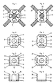
- the two clamp parts 4 and 11 are punched out of sheet steel with a sheet thickness of 2.5 mm and consist of a steel which is suitable for cold forming without cracking, has high strength, high yield strength and great elongation at break, e.g. St3K40 or with the highest demands e.g. St 67.
- the tabs 10 are bent at right angles to the bottom part 7 after the punching process. After punching and bending the tabs 10 in the lower clamp part 11, the clamp parts 4 and 11 are galvanized and chromated using surface treatment methods already used in the known cross clamps.
- the other very advantageous embodiment of the present small clamp 17 shown in FIGS. 5 to 8 differs from the preferred embodiment of the present cross clamp 1 shown in FIGS. 1 to 4 essentially only in that in the cross clamp 17 each of the two clamp parts 18 and 19 is provided with a pair of opposing claws 20 and two slots 21 for the claw pair of the other terminal part. Also in the cross clamp 17, for the same purpose as in the cross clamp 1, both clamp parts 18 and 19 are each provided with a central recess 22 and 23, and each of the two clamp parts 18 and 19 has the state shown in FIGS. 6 to 8 the connection of the two crossing wire ropes 24 and 25, two tabs 27 which are integrally connected to the base part 26 and fit into the slots 21 and are provided to form the claws 20 when the two wire ropes 24 and 25 are connected.
- the two clamp parts 18 and 19 of the cross clamp 17 consist of the same sheet with the same sheet thickness as the clamp parts 4 and 11 of the cross clamp 1 and, after the punching process and the bending of the tabs 27, become perpendicular to the base part 26 in the same way as the clamp parts 4 and 11 surface treated.
- the two wire ropes 24 and 25 are first fixed here, and then the two clamp parts 18 and 19 are offset from one another by 90 ° from both sides via the crossing point of the Wire ropes 24 and 25 pushed and the tabs 27 of the two clamp parts 18 and 19 inserted into the slots 21 of the other clamp part, and the subsequent pressing process and the bending of the end pieces 28 of the tabs 27 to form the claws 20 is then carried out again in the same manner as at the cross clamp 1.
- the load capacity of the cross clamp 17 shown in FIG. 5 is about 10 to 20% lower in terms of the opening force than with the cross clamp 1 in FIG. 1, which is due to the fact that only two of the four claws 20 of the cross clamp 17 are on the mountain side of one Stone chipping network and the other two lie on the valley side thereof, and with regard to the displacement force, the load capacity of the cross clamp 17 shown in FIG. 5 is approximately the same as that of the cross clamp 1 in FIG. 1.
Landscapes
- Engineering & Computer Science (AREA)
- General Engineering & Computer Science (AREA)
- Mechanical Engineering (AREA)
- Architecture (AREA)
- Civil Engineering (AREA)
- Structural Engineering (AREA)
- Clamps And Clips (AREA)
- Installation Of Indoor Wiring (AREA)
- Mutual Connection Of Rods And Tubes (AREA)
- Supports For Pipes And Cables (AREA)
- Catching Or Destruction (AREA)
- Communication Cables (AREA)
- Ropes Or Cables (AREA)
- Multi-Conductor Connections (AREA)
- Devices Affording Protection Of Roads Or Walls For Sound Insulation (AREA)
Claims (9)
- Serre-fil en croix (1;17) pour le serrage de deux câbles métalliques (5,6;24,25) ou tronçons de câble métallique qui se croisent au point de croisement avec deux pièces de serrage (4,11;18,19) maintenues ensemble par des griffes (9;20), exerçant une pression sur les câbles métalliques au point de croisement, et qui présentent chacune une surface d'appui pour l'un des deux câbles métalliques, respectivement, qui se croisent et dont au mois une est pourvue d'au moins une paire de griffes (9;20) opposées l'une à l'autre, caractérisé en ce qu'il est prévu pour chaque griffe (9;20) faisant partie de l'une (11;18,19) des deux pièces de serrage (4,11;18,19) à l'autre pièce de serrage (4;18,19) une fente (2;21) close tout autour pour le passage de la griffe (9;20) et en ce que la pièce d'extrémité (16;28) faisant saillie au-delà de la fente (2;21) de la griffe (9;20) passée à travers la fente (2;21) est repliée.
- Serre-fil en croix selon la revendication 1, caractérisé en ce que sont prévues deux paires de griffes (9;20) opposées l'une à l'autre qui sont disposées, de préférence, de façon décalée de 90° l'une par rapport à l'autre.
- Serre-fil en croix selon la revendication 2, caractérisé en ce que l'une (11) des deux pièces de serrage (4,11) est pourvue des deux paires de griffes (9) opposées l'une à l'autre, et que l'autre pièce de serrage (4) est pourvue des quatre fentes (2) prévues pour les deux paires de griffes.
- Serre-fil en croix selon la revendication 2, caractérisé en ce que chacune des deux pièces de serrage (18,19) est pourvue, respectivement, d'une paire de griffes opposées l'une à l'autre (20) et de deux fentes (21) pour la paire de griffes de l'autre pièce de serrage (18,19) respectivement.
- Serre-fil en croix selon la revendication 1, caractérisé en ce que l'une des deux pièces de serrage est pourvue d'une paire de griffes opposées l'une à l'autre et que l'autre pièce de serrage est pourvue des deux fentes prévues pour cette paire de griffes.
- Serre-fil en croix selon l'une des revendications 1 à 5, caractérisé en ce les griffes (9;23) sont réalisées en tôle à partir de languettes (10;27), dont les pièces d'extrémité (16;28) sont recourbées et qui sont venues de matière de préférence avec la pièce de serrage associée (11;18,19) et dont les pièces extrêmes (16;28) faisant saillie au-delà des fentes (2;21) sont arrondies de préférence en demi-cercles.
- Serre-fil en croix selon la revendication 6, caractérisé en ce que les fentes (2;21) sont, de préférence, arrondies en demi-cercles à leurs extrémités de fente, en section transversale, et présentent une largeur d'ouverture w supérieure à l'épaisseur de tôle s de la tôle constituant les languettes (10;27) ainsi qu'une longueur de fente l supérieure à la largeur de languette b et qui, pour la fixation de la position des languettes (10;21) et des griffes (9;20), respectivement, à l'intérieur des fentes (2;21) avec


w² - s²' et avec
- Liaison entre deux câbles métalliques (5,6;24,25) ou tronçons de câbles métalliques qui se croisent au moyen d'un serre-fil en croix (1;17) selon l'une des revendications 1 à 7.
- Filet en câble métallique, notamment filet contre la chute des pierres, caractérisé en ce qu'au moins une partie des croisements de deux câbles métalliques (5,6;24,25) ou de tronçons de câbles métalliques, respectivement, du filet de câble métallique est pourvue d'un serre-fil en croix (1;17) selon l'une des revendications 1 à 7.
Priority Applications (7)
| Application Number | Priority Date | Filing Date | Title |
|---|---|---|---|
| ES90117708T ES2042165T5 (es) | 1990-09-14 | 1990-09-14 | Pinza en cruz asi como red de cable metalico con pinzas en cruz. |
| DE9090117708T DE59001978D1 (de) | 1990-09-14 | 1990-09-14 | Kreuzklemme sowie drahtseilnetz mit kreuzklemmen. |
| EP90117708A EP0474910B2 (fr) | 1990-09-14 | 1990-09-14 | Collier de serrage en croix ainsi que réseau de cables avec colliers de serrage en croix |
| AT90117708T ATE91535T1 (de) | 1990-09-14 | 1990-09-14 | Kreuzklemme sowie drahtseilnetz mit kreuzklemmen. |
| CA002046479A CA2046479C (fr) | 1990-09-14 | 1991-07-08 | Element de serrage de type croise et raccord produit par ce dispositif entre deux cables de fils croises, et reseau de cables metalliques comprenant lesdits elements de serrage |
| US07/729,364 US5199673A (en) | 1990-09-14 | 1991-07-12 | Cross-type clamp and connection produced thereby between two crossed wire cables, and wire cable net with cross-type clamps |
| NO913619A NO179027C (no) | 1990-09-14 | 1991-09-13 | Kryssklemme for sammenklemming av to kryssende vaiere, samt et vaiernett utstyrt med kryssklemmer ifölge oppfinnelsen |
Applications Claiming Priority (1)
| Application Number | Priority Date | Filing Date | Title |
|---|---|---|---|
| EP90117708A EP0474910B2 (fr) | 1990-09-14 | 1990-09-14 | Collier de serrage en croix ainsi que réseau de cables avec colliers de serrage en croix |
Publications (3)
| Publication Number | Publication Date |
|---|---|
| EP0474910A1 EP0474910A1 (fr) | 1992-03-18 |
| EP0474910B1 EP0474910B1 (fr) | 1993-07-14 |
| EP0474910B2 true EP0474910B2 (fr) | 1995-06-28 |
Family
ID=8204469
Family Applications (1)
| Application Number | Title | Priority Date | Filing Date |
|---|---|---|---|
| EP90117708A Expired - Lifetime EP0474910B2 (fr) | 1990-09-14 | 1990-09-14 | Collier de serrage en croix ainsi que réseau de cables avec colliers de serrage en croix |
Country Status (7)
| Country | Link |
|---|---|
| US (1) | US5199673A (fr) |
| EP (1) | EP0474910B2 (fr) |
| AT (1) | ATE91535T1 (fr) |
| CA (1) | CA2046479C (fr) |
| DE (1) | DE59001978D1 (fr) |
| ES (1) | ES2042165T5 (fr) |
| NO (1) | NO179027C (fr) |
Families Citing this family (10)
| Publication number | Priority date | Publication date | Assignee | Title |
|---|---|---|---|---|
| US5435524A (en) * | 1993-12-06 | 1995-07-25 | Ingram; L. Howard | Impact fence |
| DE19915107B4 (de) * | 1999-04-01 | 2005-04-28 | Lothar Huck | Verbindungselement |
| EP1302595A1 (fr) | 2001-10-09 | 2003-04-16 | AVT Anker + Vorspanntechnik AG | Elément de freinage |
| EP1398417A1 (fr) | 2002-09-12 | 2004-03-17 | AVT Anker + Vorspanntechnik AG | Panneau de filet |
| DE10319639A1 (de) * | 2003-05-02 | 2004-12-02 | Carl Stahl Gmbh | Seilverbindervorrichtung |
| WO2006114450A1 (fr) * | 2005-04-21 | 2006-11-02 | Iberotalud, S.L. | Agrafe de fixation du croisement de cables dans un reseau metallique |
| JP6368622B2 (ja) * | 2014-11-05 | 2018-08-01 | 有限会社吉田構造デザイン | 緩衝装置 |
| CL2019001602A1 (es) | 2019-06-11 | 2019-10-18 | Garibaldi S A | Sistema de panel para la contención de estallidos de rocas o derrumbes en túneles mineros y obras viales formado por un bastidor solidario a una red de flejes cuyos nodos están unidos por hebillas de conexión; y procedimiento de instalación. |
| JP6870880B1 (ja) * | 2020-11-11 | 2021-05-12 | 株式会社プロテックエンジニアリング | 捕捉構造物のロープ連結具 |
| CN113478408B (zh) * | 2021-06-16 | 2023-04-21 | 吉林化工学院 | 一种基于喷嘴结构对雾化性能影响研究的喷嘴定位装置 |
Family Cites Families (5)
| Publication number | Priority date | Publication date | Assignee | Title |
|---|---|---|---|---|
| US686232A (en) * | 1901-05-16 | 1901-11-05 | Western Wire Fence Company | Wire-fence fastening-clip. |
| BE568032A (fr) * | 1957-10-01 | 1900-01-01 | ||
| GB1388326A (en) * | 1972-09-27 | 1975-03-26 | Itw Ltd | Cable clamps |
| DE2832300C2 (de) * | 1978-07-22 | 1985-06-13 | Pfeifer Seil- Und Hebetechnik Gmbh & Co, 8940 Memmingen | Klemme zur Verbindung von Seilen |
| FR2629492B1 (fr) * | 1988-03-31 | 1991-02-01 | Devaux Thierry | Barriere de protection a filet mobile |
-
1990
- 1990-09-14 ES ES90117708T patent/ES2042165T5/es not_active Expired - Lifetime
- 1990-09-14 DE DE9090117708T patent/DE59001978D1/de not_active Expired - Fee Related
- 1990-09-14 EP EP90117708A patent/EP0474910B2/fr not_active Expired - Lifetime
- 1990-09-14 AT AT90117708T patent/ATE91535T1/de not_active IP Right Cessation
-
1991
- 1991-07-08 CA CA002046479A patent/CA2046479C/fr not_active Expired - Fee Related
- 1991-07-12 US US07/729,364 patent/US5199673A/en not_active Expired - Fee Related
- 1991-09-13 NO NO913619A patent/NO179027C/no unknown
Also Published As
| Publication number | Publication date |
|---|---|
| NO913619L (no) | 1992-03-16 |
| EP0474910A1 (fr) | 1992-03-18 |
| CA2046479A1 (fr) | 1992-03-15 |
| NO179027C (no) | 1996-07-17 |
| NO179027B (no) | 1996-04-09 |
| US5199673A (en) | 1993-04-06 |
| ES2042165T3 (es) | 1993-12-01 |
| NO913619D0 (no) | 1991-09-13 |
| ES2042165T5 (es) | 1995-08-16 |
| DE59001978D1 (de) | 1993-08-19 |
| CA2046479C (fr) | 1996-03-05 |
| ATE91535T1 (de) | 1993-07-15 |
| EP0474910B1 (fr) | 1993-07-14 |
Similar Documents
| Publication | Publication Date | Title |
|---|---|---|
| DE4141308C2 (de) | Haltevorrichtung | |
| DE69738308T2 (de) | Kontaktstift mit in entgegen gesetzter Richtung orientierte Verankerungsflügel und Steckerelement | |
| AT389927B (de) | Kettenschloss fuer gliederketten | |
| EP0474910B2 (fr) | Collier de serrage en croix ainsi que réseau de cables avec colliers de serrage en croix | |
| EP0823752A2 (fr) | Connecteur à ressort pour conducteur électrique | |
| DE10250924A1 (de) | Inline-Klemmverbinder für Flex-Flachbandkabel | |
| DE69513418T2 (de) | Vögelabwehrvorrichtung | |
| DE20306280U1 (de) | Betonbauteilverbindungsvorrichtung | |
| DE3003140A1 (de) | Oese fuer eine verbindungsklemme und verfahren zu ihrer herstellung | |
| DE69516395T2 (de) | Verankerungsvorrichtung für einen träger | |
| DE2753544C2 (de) | Vorrichtung zum Anhängen von Freileitungsseilen an eine Mehrfach-Isolatorkette | |
| CH682101A5 (fr) | ||
| DE3933939C2 (fr) | ||
| EP0478886B1 (fr) | Elément de tension | |
| DE2221633A1 (de) | Bauteil fuer rundgliederketten | |
| AT410997B (de) | Abstandhalter für doppelhängeketten | |
| DE29515362U1 (de) | Isolator | |
| DE202023104046U1 (de) | Befestigungselement | |
| EP0322751B1 (fr) | Dispositif à incorporer dans un coffrage pour éléments en béton | |
| DE9205078U1 (de) | Vorrichtung zur Halterung einer Blitzfangstange auf einem Flachdach o.dgl. | |
| DE555983C (de) | Drahtgeflecht, insbesondere fuer Drahtzaeune | |
| DE1944775C3 (de) | Vorrichtung zum Verbinden sich kreuzender Seile eines Flächentragwerks od.dgl | |
| DE29509079U1 (de) | Chirurgischer Clip | |
| DE102019126395A1 (de) | Verbindungselement für Seile | |
| DE1186699B (de) | Blockkette |
Legal Events
| Date | Code | Title | Description |
|---|---|---|---|
| PUAI | Public reference made under article 153(3) epc to a published international application that has entered the european phase |
Free format text: ORIGINAL CODE: 0009012 |
|
| 17P | Request for examination filed |
Effective date: 19911107 |
|
| AK | Designated contracting states |
Kind code of ref document: A1 Designated state(s): AT CH DE ES FR GB IT LI SE |
|
| 17Q | First examination report despatched |
Effective date: 19921214 |
|
| RAP1 | Party data changed (applicant data changed or rights of an application transferred) |
Owner name: BRUGG DRAHTSEIL AG |
|
| GRAA | (expected) grant |
Free format text: ORIGINAL CODE: 0009210 |
|
| AK | Designated contracting states |
Kind code of ref document: B1 Designated state(s): AT CH DE ES FR GB IT LI SE |
|
| PG25 | Lapsed in a contracting state [announced via postgrant information from national office to epo] |
Ref country code: GB Effective date: 19930714 |
|
| REF | Corresponds to: |
Ref document number: 91535 Country of ref document: AT Date of ref document: 19930715 Kind code of ref document: T |
|
| GBT | Gb: translation of ep patent filed (gb section 77(6)(a)/1977) |
Effective date: 19930716 |
|
| REF | Corresponds to: |
Ref document number: 59001978 Country of ref document: DE Date of ref document: 19930819 |
|
| ITF | It: translation for a ep patent filed | ||
| ET | Fr: translation filed | ||
| PLBI | Opposition filed |
Free format text: ORIGINAL CODE: 0009260 |
|
| 26 | Opposition filed |
Opponent name: UTENSILERIE MECCANICHE MILANESI SPA Effective date: 19940407 |
|
| PGFP | Annual fee paid to national office [announced via postgrant information from national office to epo] |
Ref country code: SE Payment date: 19940825 Year of fee payment: 5 |
|
| PGFP | Annual fee paid to national office [announced via postgrant information from national office to epo] |
Ref country code: GB Payment date: 19940826 Year of fee payment: 5 |
|
| EAL | Se: european patent in force in sweden |
Ref document number: 90117708.9 |
|
| PUAH | Patent maintained in amended form |
Free format text: ORIGINAL CODE: 0009272 |
|
| STAA | Information on the status of an ep patent application or granted ep patent |
Free format text: STATUS: PATENT MAINTAINED AS AMENDED |
|
| 27A | Patent maintained in amended form |
Effective date: 19950628 |
|
| AK | Designated contracting states |
Kind code of ref document: B2 Designated state(s): AT CH DE ES FR GB IT LI SE |
|
| REG | Reference to a national code |
Ref country code: CH Ref legal event code: AEN |
|
| REG | Reference to a national code |
Ref country code: ES Ref legal event code: DC2A Kind code of ref document: T5 Effective date: 19950816 |
|
| ITF | It: translation for a ep patent filed | ||
| PG25 | Lapsed in a contracting state [announced via postgrant information from national office to epo] |
Ref country code: SE Free format text: LAPSE BECAUSE OF NON-PAYMENT OF DUE FEES Effective date: 19950915 |
|
| ET3 | Fr: translation filed ** decision concerning opposition | ||
| GBV | Gb: ep patent (uk) treated as always having been void in accordance with gb section 77(7)/1977 [no translation filed] |
Effective date: 19930714 |
|
| PGFP | Annual fee paid to national office [announced via postgrant information from national office to epo] |
Ref country code: FR Payment date: 19960830 Year of fee payment: 7 |
|
| PGFP | Annual fee paid to national office [announced via postgrant information from national office to epo] |
Ref country code: ES Payment date: 19970924 Year of fee payment: 8 |
|
| PG25 | Lapsed in a contracting state [announced via postgrant information from national office to epo] |
Ref country code: FR Free format text: THE PATENT HAS BEEN ANNULLED BY A DECISION OF A NATIONAL AUTHORITY Effective date: 19970930 |
|
| REG | Reference to a national code |
Ref country code: FR Ref legal event code: ST |
|
| PGFP | Annual fee paid to national office [announced via postgrant information from national office to epo] |
Ref country code: AT Payment date: 19980930 Year of fee payment: 9 |
|
| PG25 | Lapsed in a contracting state [announced via postgrant information from national office to epo] |
Ref country code: AT Free format text: LAPSE BECAUSE OF NON-PAYMENT OF DUE FEES Effective date: 19990914 |
|
| PG25 | Lapsed in a contracting state [announced via postgrant information from national office to epo] |
Ref country code: ES Free format text: LAPSE BECAUSE OF NON-PAYMENT OF DUE FEES Effective date: 19990915 |
|
| PGFP | Annual fee paid to national office [announced via postgrant information from national office to epo] |
Ref country code: CH Payment date: 20000927 Year of fee payment: 11 |
|
| PGFP | Annual fee paid to national office [announced via postgrant information from national office to epo] |
Ref country code: DE Payment date: 20001107 Year of fee payment: 11 |
|
| REG | Reference to a national code |
Ref country code: CH Ref legal event code: NV Representative=s name: LUCHS & PARTNER PATENTANWAELTE |
|
| PG25 | Lapsed in a contracting state [announced via postgrant information from national office to epo] |
Ref country code: LI Free format text: LAPSE BECAUSE OF NON-PAYMENT OF DUE FEES Effective date: 20010930 Ref country code: CH Free format text: LAPSE BECAUSE OF NON-PAYMENT OF DUE FEES Effective date: 20010930 |
|
| PG25 | Lapsed in a contracting state [announced via postgrant information from national office to epo] |
Ref country code: DE Free format text: LAPSE BECAUSE OF NON-PAYMENT OF DUE FEES Effective date: 20020501 |
|
| REG | Reference to a national code |
Ref country code: CH Ref legal event code: PL |
|
| REG | Reference to a national code |
Ref country code: ES Ref legal event code: FD2A Effective date: 20001013 |
|
| PG25 | Lapsed in a contracting state [announced via postgrant information from national office to epo] |
Ref country code: IT Free format text: LAPSE BECAUSE OF NON-PAYMENT OF DUE FEES;WARNING: LAPSES OF ITALIAN PATENTS WITH EFFECTIVE DATE BEFORE 2007 MAY HAVE OCCURRED AT ANY TIME BEFORE 2007. THE CORRECT EFFECTIVE DATE MAY BE DIFFERENT FROM THE ONE RECORDED. Effective date: 20050914 |