EP0823752A2 - Connecteur à ressort pour conducteur électrique - Google Patents
Connecteur à ressort pour conducteur électrique Download PDFInfo
- Publication number
- EP0823752A2 EP0823752A2 EP97113203A EP97113203A EP0823752A2 EP 0823752 A2 EP0823752 A2 EP 0823752A2 EP 97113203 A EP97113203 A EP 97113203A EP 97113203 A EP97113203 A EP 97113203A EP 0823752 A2 EP0823752 A2 EP 0823752A2
- Authority
- EP
- European Patent Office
- Prior art keywords
- tension spring
- conductor
- clamping
- spring connection
- connection according
- Prior art date
- Legal status (The legal status is an assumption and is not a legal conclusion. Google has not performed a legal analysis and makes no representation as to the accuracy of the status listed.)
- Granted
Links
Images

Classifications
-
- H—ELECTRICITY
- H01—ELECTRIC ELEMENTS
- H01R—ELECTRICALLY-CONDUCTIVE CONNECTIONS; STRUCTURAL ASSOCIATIONS OF A PLURALITY OF MUTUALLY-INSULATED ELECTRICAL CONNECTING ELEMENTS; COUPLING DEVICES; CURRENT COLLECTORS
- H01R4/00—Electrically-conductive connections between two or more conductive members in direct contact, i.e. touching one another; Means for effecting or maintaining such contact; Electrically-conductive connections having two or more spaced connecting locations for conductors and using contact members penetrating insulation
- H01R4/28—Clamped connections, spring connections
- H01R4/48—Clamped connections, spring connections utilising a spring, clip, or other resilient member
- H01R4/4809—Clamped connections, spring connections utilising a spring, clip, or other resilient member using a leaf spring to bias the conductor toward the busbar
- H01R4/4811—Spring details
- H01R4/4816—Spring details the spring shape preventing insertion of the conductor end when the spring is unbiased
-
- H—ELECTRICITY
- H01—ELECTRIC ELEMENTS
- H01R—ELECTRICALLY-CONDUCTIVE CONNECTIONS; STRUCTURAL ASSOCIATIONS OF A PLURALITY OF MUTUALLY-INSULATED ELECTRICAL CONNECTING ELEMENTS; COUPLING DEVICES; CURRENT COLLECTORS
- H01R4/00—Electrically-conductive connections between two or more conductive members in direct contact, i.e. touching one another; Means for effecting or maintaining such contact; Electrically-conductive connections having two or more spaced connecting locations for conductors and using contact members penetrating insulation
- H01R4/28—Clamped connections, spring connections
- H01R4/48—Clamped connections, spring connections utilising a spring, clip, or other resilient member
- H01R4/4809—Clamped connections, spring connections utilising a spring, clip, or other resilient member using a leaf spring to bias the conductor toward the busbar
- H01R4/4846—Busbar details
Definitions
- the present invention relates to a tension spring connection for electrical conductors the preamble of claim 1.
- a tension spring connection is known for example from DE-OS-39 11 459.
- the The spring force of the tension spring cannot be increased arbitrarily, so that to increase the surface pressure minimizing the printing area remains as the only alternative.
- connection should be gas-tight.
- the present invention is therefore based on the object of a tension spring connection of the generic type so that the surface pressure in Connection area between the tension spring or the busbar and the conductor with unchanged spring force of the tension spring, even with the smallest tension spring connection elements, is as big as possible.
- the busbar a sharp-edged area on the side facing the conductor has, which runs transversely to the longitudinal axis of the conductor and which is also digs into the conductor when pressed against it.
- This sharp-edged design can be achieved, for example, in that the busbar has a tongue-like punching, the free end in Is bent towards the conductor, which results in a sharp clamping edge.
- this clamping edge the tongue is offset in relation to the clamping edge of the window opening is.
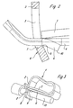
- a tension spring connection which consists of a tension spring 1 and a Busbar 4 exists.
- the tension spring 1 is loop-shaped and has a clamping leg 2 and a contact leg 3. On this, the busbar 4 is fixed, which in a window cut 5 provided in the clamping leg 2 passes.
- a clamping edge 9 is formed through which a pin-shaped conductor 11, the as can be seen from FIG. 3, can be guided through the window cutout to the Busbar 4 is pressed.
- the busbar 4 has a pronounced tongue 6, which is under a certain Angle in the direction of the end region 8 of the clamping leg 2 inclines and whose free outer edge also forms a clamping edge 10, which is in the use position, that is, with the conductor 11 inserted, on the clamping edge 9 opposite Side of the conductor 11 is supported and there due to the clamping leg 2 applied spring force, which presses the conductor 11 against the clamping edge 10, digs in.
- crank angle of the end region 8 and the angle of inclination of the tongue 6 are the to determine the respective requirements, which depend on the conductor cross-section.
Landscapes
- Installation Of Bus-Bars (AREA)
- Connections Effected By Soldering, Adhesion, Or Permanent Deformation (AREA)
- Details Of Connecting Devices For Male And Female Coupling (AREA)
Applications Claiming Priority (2)
| Application Number | Priority Date | Filing Date | Title |
|---|---|---|---|
| DE19632187A DE19632187C2 (de) | 1996-08-09 | 1996-08-09 | Zugfederanschluß für elektrische Leiter |
| DE19632187 | 1996-08-09 |
Publications (3)
| Publication Number | Publication Date |
|---|---|
| EP0823752A2 true EP0823752A2 (fr) | 1998-02-11 |
| EP0823752A3 EP0823752A3 (fr) | 1999-03-10 |
| EP0823752B1 EP0823752B1 (fr) | 2003-03-12 |
Family
ID=7802239
Family Applications (1)
| Application Number | Title | Priority Date | Filing Date |
|---|---|---|---|
| EP97113203A Expired - Lifetime EP0823752B1 (fr) | 1996-08-09 | 1997-07-31 | Connecteur à ressort pour conducteur électrique |
Country Status (3)
| Country | Link |
|---|---|
| US (1) | US5938484A (fr) |
| EP (1) | EP0823752B1 (fr) |
| DE (2) | DE19632187C2 (fr) |
Cited By (4)
| Publication number | Priority date | Publication date | Assignee | Title |
|---|---|---|---|---|
| FR2782848A1 (fr) * | 1998-09-02 | 2000-03-03 | Entrelec Sa | Dispositif elastique permettant de realiser une connexion electrique dans une borne de raccordement |
| EP1059705A3 (fr) * | 1999-06-11 | 2002-04-17 | Weidmüller Interface GmbH & Co. | Connecteur à ressort pour un conducteur électrique |
| FR2936656A1 (fr) * | 2008-09-29 | 2010-04-02 | Legrand France | Borne de connexion electrique automatique |
| FR2954604A1 (fr) * | 2009-12-22 | 2011-06-24 | Legrand France | Borne de connexion electrique automatique et appareillage electrique comportant une telle borne |
Families Citing this family (18)
| Publication number | Priority date | Publication date | Assignee | Title |
|---|---|---|---|---|
| DE19615706A1 (de) * | 1996-04-22 | 1997-10-23 | Teves Gmbh Alfred | Aggregat |
| DE19916755B4 (de) | 1999-04-14 | 2007-06-28 | Weidmüller Interface Gmbh & Co. | Zugfederklemme |
| DE29919903U1 (de) * | 1999-11-12 | 2001-03-29 | Weidmüller Interface GmbH & Co, 32760 Detmold | Zugfederanschluß für große Leiterquerschnitte |
| FR2809537B1 (fr) * | 2000-05-24 | 2003-09-26 | Entrelec Sa | Ressort de connexion |
| DE10134417C1 (de) * | 2001-07-19 | 2003-01-23 | Phoenix Contact Gmbh & Co | Elektrische Anschluß- oder Verbindungseinrichtung |
| ATE496406T1 (de) * | 2002-04-12 | 2011-02-15 | Weidmueller Interface | Anschlussvorrichtung für leiter |
| DE10304493A1 (de) * | 2003-02-05 | 2004-08-26 | Phoenix Contact Gmbh & Co. Kg | Zugfeder für eine elektrische Klemme |
| US6893286B2 (en) * | 2003-09-06 | 2005-05-17 | Weidmüller Interface GmbH & Co. KG | Connector apparatus adapted for the direct plug-in connection of conductors |
| DE202005013056U1 (de) | 2005-08-18 | 2007-01-04 | Weidmüller Interface GmbH & Co. KG | Elektrische Anschlussvorrichtung |
| US9130285B2 (en) * | 2012-09-05 | 2015-09-08 | Hubbell Incorporated | Push wire connector having a spring biasing member |
| US9576762B2 (en) | 2015-04-03 | 2017-02-21 | Eaton Corporation | Electrical switching apparatus and secondary disconnect assembly with error-proofing features therefor |
| US9396889B1 (en) | 2015-04-03 | 2016-07-19 | Eaton Corporation | Electrical switching apparatus and secondary disconnect assembly with cradle assembly alignment and positioning features therefor |
| US9570261B2 (en) | 2015-04-03 | 2017-02-14 | Eaton Corporation | Electrical switching apparatus and secondary disconnect assembly with contact alignment features therefor |
| US9336977B1 (en) | 2015-04-03 | 2016-05-10 | Eaton Corporation | Electrical switching apparatus and secondary disconnect assembly with terminal retention and correction features therefor |
| DE102016111536A1 (de) * | 2016-06-23 | 2017-12-28 | Wago Verwaltungsgesellschaft Mbh | Kontakteinsatz einer Federkraftanschlussklemme sowie damit ausgebildete Federkraftanschlussklemme |
| TWM550925U (zh) * | 2017-05-26 | 2017-10-21 | Switchlab Inc | 用於電聯接端子之金屬彈片保護結構 |
| US10153562B1 (en) * | 2017-11-08 | 2018-12-11 | Xiamen Ghgm Industrial Trade Co., Ltd. | Patch cord connecting metal terminal having a pushbutton on a lateral side of a resilient arm |
| GB2592263B (en) * | 2020-02-24 | 2024-06-12 | Linian Lab Ltd | Fastening device |
Family Cites Families (10)
| Publication number | Priority date | Publication date | Assignee | Title |
|---|---|---|---|---|
| FR1602459A (fr) * | 1968-10-23 | 1970-11-30 | ||
| DE3122303A1 (de) * | 1981-06-04 | 1983-01-27 | Felten & Guilleaume Energietechnik GmbH, 5000 Köln | Federklemme zum anschluss isolierter elektrischer leiter |
| DE3504317A1 (de) * | 1985-02-08 | 1986-08-14 | Licentia Patent-Verwaltungs-Gmbh, 6000 Frankfurt | Klemme fuer elektrische leiter |
| DE3514099C2 (de) * | 1985-04-16 | 1994-11-17 | Wago Verwaltungs Gmbh | Verbindungsklemme für elektrische Leiter |
| DE3911457A1 (de) * | 1989-04-05 | 1990-10-18 | Ifm Electronic Gmbh | Verfahren und schaltungsanordnung zur umsetzung einer analogen messspannung in ein digitales messsignal |
| DE3911459A1 (de) * | 1989-04-05 | 1990-10-11 | Wago Verwaltungs Gmbh | Schraubenlose anschluss- und/oder verbindungsklemme |
| DE4016770A1 (de) * | 1990-05-25 | 1991-11-28 | Guenter Trautmann | Kabelverbinder - oder anschlussklemme fuer massivdraht und feindrahtlitze gleichzeitig |
| DE4237733C1 (de) * | 1992-11-09 | 1993-12-23 | Weidmueller Interface | Schraubenlose Anschlußklemme für elektrische Leiter |
| GB9311559D0 (en) * | 1993-06-04 | 1993-07-21 | Amp Gmbh | Spring clamp actuator |
| GB9508153D0 (en) * | 1995-04-21 | 1995-06-07 | Amp Gmbh | Spring clamp terminal |
-
1996
- 1996-08-09 DE DE19632187A patent/DE19632187C2/de not_active Expired - Fee Related
-
1997
- 1997-07-31 DE DE59709471T patent/DE59709471D1/de not_active Expired - Lifetime
- 1997-07-31 EP EP97113203A patent/EP0823752B1/fr not_active Expired - Lifetime
- 1997-08-07 US US08/911,363 patent/US5938484A/en not_active Expired - Lifetime
Cited By (6)
| Publication number | Priority date | Publication date | Assignee | Title |
|---|---|---|---|---|
| FR2782848A1 (fr) * | 1998-09-02 | 2000-03-03 | Entrelec Sa | Dispositif elastique permettant de realiser une connexion electrique dans une borne de raccordement |
| US6183288B1 (en) | 1998-09-02 | 2001-02-06 | Entrelec S.A. | Resilient device allowing an electrical connection to be made in a connection terminal |
| DE19939572B4 (de) * | 1998-09-02 | 2007-06-28 | Entrelec S.A. | Federklemmvorrichtung für den Anschluß eines elektrischen Leiters in einer Anschlußanordnung |
| EP1059705A3 (fr) * | 1999-06-11 | 2002-04-17 | Weidmüller Interface GmbH & Co. | Connecteur à ressort pour un conducteur électrique |
| FR2936656A1 (fr) * | 2008-09-29 | 2010-04-02 | Legrand France | Borne de connexion electrique automatique |
| FR2954604A1 (fr) * | 2009-12-22 | 2011-06-24 | Legrand France | Borne de connexion electrique automatique et appareillage electrique comportant une telle borne |
Also Published As
| Publication number | Publication date |
|---|---|
| US5938484A (en) | 1999-08-17 |
| EP0823752A3 (fr) | 1999-03-10 |
| DE19632187A1 (de) | 1998-02-12 |
| DE59709471D1 (de) | 2003-04-17 |
| EP0823752B1 (fr) | 2003-03-12 |
| DE19632187C2 (de) | 1998-07-02 |
Similar Documents
| Publication | Publication Date | Title |
|---|---|---|
| DE19632187C2 (de) | Zugfederanschluß für elektrische Leiter | |
| DE3811974C2 (fr) | ||
| DE2633972C3 (de) | Anordnung zum Verbinden zweier Bauteile | |
| DE3127704C2 (de) | Verbinder zum Anschließen eines Vielleiter-Flachkabels | |
| DE1765818C3 (de) | Verbindungsklemme zum Andrücken an elektrische Drähte | |
| DE202007001701U1 (de) | Universalkontakt | |
| DE8816798U1 (de) | Stiftförmiges Kontaktelement zur Befestigung in Leiterplattenbohrungen | |
| DE3543596C2 (de) | Schraubklemme | |
| DE2435461A1 (de) | Elektrischer kontaktstift | |
| DE102007046616A1 (de) | Schneidklemmanschluss | |
| DE3818497C5 (de) | Anschlußblock für eine Kabelabschlußeinheit | |
| DE3784911T2 (de) | Nachgiebiger einpressstift. | |
| DE102019120305B4 (de) | Leiteranschlussklemme | |
| DE3118057C2 (de) | Anschlußklemme für elektrische Leiter | |
| DE102018206849B4 (de) | Vorrichtung zur klemmenden Befestigung | |
| EP0901186B1 (fr) | Borne de connexion pour des câbles blindés | |
| DE102008015374B4 (de) | Elektrische Klemme | |
| EP0481309A2 (fr) | Borne pour disjoncteur | |
| EP0704931B1 (fr) | Dispositif de serrage pour la connexion des câbles à des barres | |
| DE2052388A1 (de) | Anschlussklemme fur elektrische Apparate | |
| EP2242146A2 (fr) | Dispositif de serrage ainsi que réglette coupe-circuit ou séparateur dotés d'un dispositif de serrage | |
| DE29616837U1 (de) | Reihenklemme mit Stromschiene | |
| EP3855572A1 (fr) | Borne de liaison | |
| EP1335138B1 (fr) | Attache pour barre profilée | |
| DE102008064632A1 (de) | Elektrische Klemme |
Legal Events
| Date | Code | Title | Description |
|---|---|---|---|
| PUAI | Public reference made under article 153(3) epc to a published international application that has entered the european phase |
Free format text: ORIGINAL CODE: 0009012 |
|
| 17P | Request for examination filed |
Effective date: 19970827 |
|
| AK | Designated contracting states |
Kind code of ref document: A2 Designated state(s): DE ES FR GB IT |
|
| AX | Request for extension of the european patent |
Free format text: AL;LT;LV;RO;SI |
|
| PUAL | Search report despatched |
Free format text: ORIGINAL CODE: 0009013 |
|
| AK | Designated contracting states |
Kind code of ref document: A3 Designated state(s): AT BE CH DE DK ES FI FR GB GR IE IT LI LU MC NL PT SE |
|
| AX | Request for extension of the european patent |
Free format text: AL;LT;LV;RO;SI |
|
| AKX | Designation fees paid |
Free format text: DE ES FR GB IT |
|
| 17Q | First examination report despatched |
Effective date: 19991215 |
|
| GRAH | Despatch of communication of intention to grant a patent |
Free format text: ORIGINAL CODE: EPIDOS IGRA |
|
| GRAH | Despatch of communication of intention to grant a patent |
Free format text: ORIGINAL CODE: EPIDOS IGRA |
|
| GRAA | (expected) grant |
Free format text: ORIGINAL CODE: 0009210 |
|
| AK | Designated contracting states |
Designated state(s): DE ES FR GB IT |
|
| PG25 | Lapsed in a contracting state [announced via postgrant information from national office to epo] |
Ref country code: GB Free format text: LAPSE BECAUSE OF FAILURE TO SUBMIT A TRANSLATION OF THE DESCRIPTION OR TO PAY THE FEE WITHIN THE PRESCRIBED TIME-LIMIT Effective date: 20030312 |
|
| REG | Reference to a national code |
Ref country code: GB Ref legal event code: FG4D Free format text: NOT ENGLISH |
|
| REF | Corresponds to: |
Ref document number: 59709471 Country of ref document: DE Date of ref document: 20030417 Kind code of ref document: P |
|
| GBV | Gb: ep patent (uk) treated as always having been void in accordance with gb section 77(7)/1977 [no translation filed] |
Effective date: 20030312 |
|
| PG25 | Lapsed in a contracting state [announced via postgrant information from national office to epo] |
Ref country code: ES Free format text: LAPSE BECAUSE OF FAILURE TO SUBMIT A TRANSLATION OF THE DESCRIPTION OR TO PAY THE FEE WITHIN THE PRESCRIBED TIME-LIMIT Effective date: 20030930 |
|
| ET | Fr: translation filed | ||
| PLBE | No opposition filed within time limit |
Free format text: ORIGINAL CODE: 0009261 |
|
| STAA | Information on the status of an ep patent application or granted ep patent |
Free format text: STATUS: NO OPPOSITION FILED WITHIN TIME LIMIT |
|
| 26N | No opposition filed |
Effective date: 20031215 |
|
| PGFP | Annual fee paid to national office [announced via postgrant information from national office to epo] |
Ref country code: FR Payment date: 20110729 Year of fee payment: 15 |
|
| PGFP | Annual fee paid to national office [announced via postgrant information from national office to epo] |
Ref country code: DE Payment date: 20110722 Year of fee payment: 15 |
|
| PGFP | Annual fee paid to national office [announced via postgrant information from national office to epo] |
Ref country code: IT Payment date: 20110726 Year of fee payment: 15 |
|
| REG | Reference to a national code |
Ref country code: FR Ref legal event code: ST Effective date: 20130329 |
|
| PG25 | Lapsed in a contracting state [announced via postgrant information from national office to epo] |
Ref country code: DE Free format text: LAPSE BECAUSE OF NON-PAYMENT OF DUE FEES Effective date: 20130201 Ref country code: FR Free format text: LAPSE BECAUSE OF NON-PAYMENT OF DUE FEES Effective date: 20120731 |
|
| REG | Reference to a national code |
Ref country code: DE Ref legal event code: R119 Ref document number: 59709471 Country of ref document: DE Effective date: 20130201 |
|
| PG25 | Lapsed in a contracting state [announced via postgrant information from national office to epo] |
Ref country code: IT Free format text: LAPSE BECAUSE OF NON-PAYMENT OF DUE FEES Effective date: 20120731 |