EP0474974A1 - Profilé d'extrémité de rive - Google Patents
Profilé d'extrémité de rive Download PDFInfo
- Publication number
- EP0474974A1 EP0474974A1 EP91109100A EP91109100A EP0474974A1 EP 0474974 A1 EP0474974 A1 EP 0474974A1 EP 91109100 A EP91109100 A EP 91109100A EP 91109100 A EP91109100 A EP 91109100A EP 0474974 A1 EP0474974 A1 EP 0474974A1
- Authority
- EP
- European Patent Office
- Prior art keywords
- eaves
- profile
- projections
- eaves end
- profile according
- Prior art date
- Legal status (The legal status is an assumption and is not a legal conclusion. Google has not performed a legal analysis and makes no representation as to the accuracy of the status listed.)
- Withdrawn
Links
Images



Classifications
-
- E—FIXED CONSTRUCTIONS
- E04—BUILDING
- E04D—ROOF COVERINGS; SKY-LIGHTS; GUTTERS; ROOF-WORKING TOOLS
- E04D13/00—Special arrangements or devices in connection with roof coverings; Protection against birds; Roof drainage ; Sky-lights
- E04D13/17—Ventilation of roof coverings not otherwise provided for
- E04D13/178—Ventilation of roof coverings not otherwise provided for on the eaves of the roof
Definitions
- the invention relates to an eaves end profile of the type specified in the preamble of claim 1.
- an underlayment or a sealing membrane is applied to the rafters or to the formwork to protect the rafters and thermal insulation as well as to protect the formwork applied to the rafters.
- the roofing membrane or waterproofing membrane can get wet on the tops of it due to the penetration of snow or rain, especially in the case of damaged goats, steep roofs must be ventilated.
- an air inlet must be possible in the eaves area between the roof tiles and the sarking membrane or waterproofing membrane, the air outlet taking place via ridge fan roof elements.
- the roofing membrane In order to prevent the ingress of moisture between the roofing membrane and the rafters or the heat seal, the roofing membrane must be fastened with an eaves end profile. The same applies to the sealing membrane with regard to the penetration of moisture between the sealing membrane and the formwork.
- Known eaves end profiles have a ventilation eaves strip firmly attached, for example by soldering or welding, on which the eaves tiles are supported.
- Known eaves end profiles for fastening the soffit or sealing membrane in the ridge direction behind the ventilation eaves strip continue to have a series of upward-pointing tips on which the soffit or Sealing membrane is pressed to create a connection with the eaves end profile and the underlay or sealing membrane.
- the invention is therefore based on the object of providing an eaves end profile in which the underlayment or sealing membrane can be connected securely and permanently to the eaves end profile.
- the underlayment or sealing membrane should not be damaged and the eaves end profile should be fastened quickly and easily.
- roofing membranes and sealing membranes. Whether roofing membranes or waterproofing membranes are used depends on the roof structure chosen. If only sealing membranes are referred to in the following, this term is also intended to include underlay membranes.
- the invention has the advantage that the sealing membrane can be firmly clamped between the profile projections over the entire length of the eaves end profile. Snow flying and rain can no longer penetrate between the sealing membrane and the formwork, since the sealing membrane is fixed evenly between the projections over its entire width.
- the opposite side surfaces of the profile projections are inclined to each other. This ensures that the clamping brackets used to fix or clamp the sealing membrane are held securely by the projections and can only be released again with greater effort. It follows that the sealing membrane is also securely fixed.
- clamping brackets are provided between the projections for fixing the sealing sheet.
- the ends of the clamping brackets which are made of flexible material, are pressed against one another during insertion between the projections and are inserted into the area between the projections, taking the sealing sheet with them. After releasing the clamps, they expand and lie securely on the projections, the inner surfaces of which engage underneath.
- more or fewer clamping brackets can be used, so that a secure application of the sealing membrane on the eaves end profile is always guaranteed.
- the clamping bracket provided according to the invention for fixing the underlayment or sealing sheet can have different shapes.
- a leaf-shaped clamping bracket or a clamping bracket V-shaped cross section is preferred.
- both versions of the clamping bracket can be provided with outwardly bent end sections which are inclined opposite to the inclined side surfaces of the projections and whose apex, when the clamping bracket is clamped between the projections, bear against the base surface of the eaves end profile and the end edges thereof against the inclined side surfaces, and are attacked by stops that protrude on the side surfaces.
- This ensures a particularly secure mounting of the underlayment or sealing sheets, which cannot be accidentally released even during assembly on site, for example by stepping in there. If, for example, the protrusions are stepped on the side, the protruding stops prevent the end portions of the clamp bracket from disengaging.
- clamping bracket V-shaped cross-section its legs are so long and connected to one another via a widened base section that this clamping bracket can be used as a replacement for conventional ventilation eaves strips is suitable, namely for laying eaves bricks.
- the sealing strip ends between the projections.
- the end of the sealing membrane is protected between the projections of the eaves end profile, so that, for example, penetrating wind cannot raise the end of the sealing membrane, since the wind flow is guided over the end region of the sealing membrane.
- a perforated end region adjoins the projection facing the eaves edge.
- Roofs with a roof overhang can be ventilated and vented in place of raised ventilation eaves over the perforated area mentioned above. The air flow enters the roof space almost vertically through the perforated area.
- eaves end profiles are connected to one another via profile connectors.
- profile connectors eaves end profiles of any length can be produced, with individual eaves end profiles of different lengths being used for this purpose.
- the profile connectors have ribs corresponding to the projections of the eaves end profile, namely complementary in profile.
- These ribs consist of narrow strips running perpendicular to the direction of the eaves, the side view of which corresponds to the cross section of the eaves end profile, in particular in the area of the projections. This provides guidance when the eaves end profiles are pushed onto the profile connectors, which at the same time ensures a secure connection and reliably prevents the eaves end profiles from shifting relative to one another.
- the profile connectors are further equipped with support ribs for the eaves end profiles, which are arranged between the profile ribs.
- These support ribs are narrow strips of the same height that run perpendicular to the direction of the eaves. Since these correspond to the eaves end profiles in the area between the projections and are not lowered, the eaves end profiles rest on the supporting ribs. This ensures a safe and specific position of the eaves end profiles in relation to the profile connectors.
- the profile connectors have parallel grooves on the top perpendicular to the eaves direction. These grooves cause a significant increase in the section modulus's moment of resistance with respect to the axis of the profile connector, which runs parallel to the eaves edge. Due to the large section modulus, the eaves end profiles are held securely on the profile connectors and cannot bend them, so that the eaves end profiles can assume a secure and firm position in the area between the rafters.
- the grooves provided have no influence on the section modulus with respect to the axis of the profile connector running perpendicular to the eaves edge. This is also desirable because the profile connectors may be bent upwards when the eaves end profiles are slid on and should therefore be designed as flexibly as possible in this direction.
- the eaves end profiles end with a strip running downwards, on the inside of which an inward projection is arranged.
- the End area of the profile connector facing the eaves can be supported on the provided, inward projection and additionally represents a guide when connecting the eaves end profiles to the profile connectors.
- the profile connectors consist of a plastic injection molded part.
- the dimensions of the profile connector can remain the same, so that the cheap process of plastic injection molding can be used.
- plastic with respect to the eaves end profile and the profile connector also has the advantage that these parts are insensitive to moisture and practically never need to be replaced, since they are very durable and also cannot rust through.
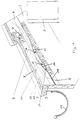
- Fig. 1 shows schematically a roof structure in the eaves area with an eaves termination with roof overhang.
- a rafter 2 rests on the schematically indicated outer wall 1, on the upper side of which a formwork 3 is applied, perpendicular to the rafter 2.
- a sealing membrane 4 is applied to the top of the formwork 3.
- a counter battens 6 is attached to the formwork 3. The counter battens run in the direction of the rafters.
- a roof batten is then applied perpendicular to the rafters on the counter battens.
- the last roof batten 7 is shown in cross section in FIG. 1.
- the part of a eaves tile 8 facing the ridge is supported on the roof batten 7.
- the end region of the eaves tile 8 is supported on the front board 9.
- the gutter 11 is fastened to the eaves wedge 10 in such a way that water running down from the top of the brick is collected by the gutter.
- the front board 9 and Eaves wedge 10 creates the space required for ventilation between the roof covering and the sealing membrane 4.
- the sealing membrane 4 lies in the roof area on the formwork 3 and in the eaves area merges with an eaves end profile 12, which in turn is applied to the formwork 3.
- the eaves end profile 12 has two projections 13 and 14 in cross section.
- the projections 13 and 14 of the eaves end profile 12 are triangular in cross section, the opposite side surfaces 15 and 16 being inclined to one another. Due to this design, the sealing sheet 4 running out in the area between the projections 13 and 14 can be securely and firmly clamped to the inner edge of the projection 13 by means of a leaf-shaped clamping bracket 17. Due to the described inclination of the side surfaces 13 and 14, the clamping bracket 17 cannot easily unintentionally loosen.
- the air flow 5 can enter through this perforated end region 18 for ventilation of the roof, the formwork 3 naturally not being able to be present in this region.
- the air flow 5 sweeps over the end region of the roofing membrane 4 due to the design of the projection 14 and cannot therefore lift off the end region of the sealing membrane 4.
- lifting off the sealing sheet 4 in the area between the projections 13 and 14 would not allow moisture to penetrate into the circuit 3, since the sealing sheet is held securely and securely via the clamping bracket 17.
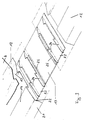
- the profile connector 19 is also shown, on which the eaves end profile 12 is attached.
- FIG. 2 also clearly shows the perforated end region 18 of the eaves end profile 12.
- a profile connector 19 can first be attached to the rafters and then an eaves end profile 12 can be pushed onto it. A further profile connector 19 can then be inserted into the free end of the eaves end profile 12 and then attached to the associated rafters 2. If the eaves end profiles 12 are kept shorter than the inside width of the rafters 2, a subsequent installation can also be carried out. The profile connector 19 is raised somewhat, the eaves end profile 12 is plugged on and first pushed on as far as possible on the rafters. Then the eaves end profile 12 is moved in the direction of the second profile connector 19, plugged in there and mediated. The eaves end profiles 12 have parallel longitudinal grooves 20 to increase their section modulus about the short axis.
- FIG. 3 A preferred embodiment of an eaves end profile 12 according to the invention with profile connector 19 is shown in FIG. 3.
- the end region of the eaves end profile 12 facing the eaves edge is not shown perforated, but can have a perforation 18 as shown in FIG. 2 at any time.
- the end region of the eaves end profile 12 extends in the form of a strip 21 approximately downwards from the end region of the eaves end profile 12.
- At the A projection 22 is provided on the inside of the strip 21, on which the end region 23 of the profile connector 19 can be supported and which also serves as a guide for the profile connector 19.
- the sealing membrane 4 is also guided over the projection 13 and runs out in the region between the projection 13 and the projection 14.
- the profile connector 19 has ribs 24 which are adapted to the cross-sectional shape of the eaves end profile 12.
- ribs 24 are arranged in the side regions of the profile connector 19. They serve for a secure hold and for guiding the eaves end profiles 12.
- support ribs 25 are arranged behind the ribs 24, as seen inwards.
- the support ribs 25 are designed as rectangular in cross-section, extending perpendicular to the profile connector 19 and are so high in the intermediate area between the projections 13 and 14 of the eaves end profile 12 that the aforementioned area rests on the support ribs 25.
- Fig. 4 shows schematically a cross section similar to Fig. 1, wherein the roof shown in Fig. 4 has an eaves finish without a roof overhang.
- identical parts are again identified with the same numbers in FIG. 4.
- the counter battens 6 according to FIG. 4 are not led to the rafter end, but ends before the rafter closure.
- the last roof battens 7 are placed, on which the end of the eaves tile 8, which faces the ridge, is supported. Due to the missing roof overhang, ventilation takes place via the raised free end of the eaves tile 8.
- the free end of the eaves tile 8 is raised with the help of the clamping bracket, which is designed here in the form of a V-shaped bracket 26, the two inclined legs of which are connected to one another via a widened base section, which is used to support the eaves tile 8 serves.
- the clamp bracket 26 therefore has several tasks.
- the clamping bracket 26 serves to create the space required for the air flow 5 between the covering and the sealing membrane.
- the flat upper side of the clamping bracket 26 serves as a support surface for the end region of the eave brick 8.
- the clamping bracket 26 has another task, namely to fix the sealing sheet 4 firmly on the eaves end profile 12, more precisely on its projection 13.
- the eaves end profiles 12 are applied to the battens during assembly and connected to one another via profile connectors 19. It does not matter whether the eaves profiles have 12 different lengths. This results in a continuous area over the entire eaves edge between the projections 13 and 14, in which the roofing membrane 4 can be inserted.
- the eaves end profiles 12 are not interrupted by the counter battens 6 or the rafters 2.
- the function of the leaf-shaped clamping bracket shown in FIGS. 1 and 2 is performed by the V-shaped clamping bracket 26, which is pressed onto the eaves end profile 12 between the projections 13 and 14. Since the eaves end profile 12 is made of flexible material, preferably plastic, it can be clipped like a clip between the projections 13 and 14, the legs of the clamping bracket 26 are inclined so that their end portions when the bracket is inserted essentially in a form-fitting manner on the inwardly inclined side surfaces 15 and 16 of the projections 12 and 13 abut. In this embodiment, the sealing sheet 4 is therefore fixed over its entire width pressed against the projection 13.
- the end region of the sealing sheet 4 lying in the area between the projections 13 and 14 is firmly attached to the eaves end profile 12 via the underside of the clamping bracket 26, so that a possibly vertically occurring air stream 5 cannot raise the end of the sealing sheet 4.
- the clamping brackets 17 and 26 described in more detail above ensure a secure mounting of the underlayment or sealing membrane 4.
- Fig. 5 an embodiment of the clamping bracket and its holder is shown in the eaves end profile, with which it is ensured that the clamping bracket remains in its holder even when subjected to a side impact by a step or the like.
- the V-shaped clamp bracket 26 is bent at its free end portions 31.
- the bend is directed outwards, so that the end sections 31 are inclined in the opposite direction to the inclination of the side surfaces 15, 16 of the projections 13, 14.
- stops projecting from these are formed on the side surfaces.
- the leg of the clamping bracket gripped by the step is pushed inward and then springs back into its original position. Due to the bent end portion 31 and the protruding stop 32, the resilient end portion 31 is unable to snap or slip out of its engagement with the inclined side surface of the respective projection. In the same way The other of the two legs of the clamping bracket 26, which are not acted upon directly by the step, and which undergoes a rotational movement, remains in their held position on the side surface below the stop 32.
Landscapes
- Engineering & Computer Science (AREA)
- Architecture (AREA)
- Civil Engineering (AREA)
- Structural Engineering (AREA)
- Building Environments (AREA)
Applications Claiming Priority (4)
| Application Number | Priority Date | Filing Date | Title |
|---|---|---|---|
| DE9011093U | 1990-07-26 | ||
| DE9011093U DE9011093U1 (de) | 1990-07-26 | 1990-07-26 | Traufabschlußprofil |
| DE9100995U | 1991-01-29 | ||
| DE9100995U DE9100995U1 (de) | 1991-01-29 | 1991-01-29 | Traufabschlußprofil |
Publications (1)
| Publication Number | Publication Date |
|---|---|
| EP0474974A1 true EP0474974A1 (fr) | 1992-03-18 |
Family
ID=25956976
Family Applications (1)
| Application Number | Title | Priority Date | Filing Date |
|---|---|---|---|
| EP91109100A Withdrawn EP0474974A1 (fr) | 1990-07-26 | 1991-06-04 | Profilé d'extrémité de rive |
Country Status (1)
| Country | Link |
|---|---|
| EP (1) | EP0474974A1 (fr) |
Cited By (4)
| Publication number | Priority date | Publication date | Assignee | Title |
|---|---|---|---|---|
| EP0622500A1 (fr) * | 1993-04-28 | 1994-11-02 | Klaus Henn | Dispositif d'aération de toits |
| WO1997034062A1 (fr) * | 1996-03-11 | 1997-09-18 | Polysheet A/S | Avancee de toit a ventilation |
| EP0853171A3 (fr) * | 1997-01-11 | 1999-04-14 | Braas GmbH | Dispositif de support d'un accessoire sur une rive de toit |
| EP3385467A1 (fr) * | 2017-04-07 | 2018-10-10 | Rheinzink GmbH & Co. KG | Larmier |
Citations (8)
| Publication number | Priority date | Publication date | Assignee | Title |
|---|---|---|---|---|
| GB1025821A (en) * | 1961-02-05 | 1966-04-14 | John Stanley Vincent Marling B | Improvements in or relating to structures formed by joining together adjacent edges of sheeting by clamps |
| BE806388A (fr) * | 1972-12-06 | 1974-02-15 | Uhl Kg Geb | Revetement pour le bord d'un toit |
| DE2529575A1 (de) * | 1975-07-02 | 1977-01-20 | Gunnar Serneblad | Rampe fuer unterstuetzung und befestigung eines dachbelags |
| FR2384143A1 (fr) * | 1977-03-17 | 1978-10-13 | Sotram Sarl | Perfectionnements apportes aux dispositifs pince films, en particulier pour la fixation de films de recouvrement en matiere plastique |
| GB2118991A (en) * | 1981-12-07 | 1983-11-09 | Barry Cliff | Ventilating roofs |
| GB2127060A (en) * | 1982-09-13 | 1984-04-04 | Redland Roof Tiles Ltd | Improvements in roof ventilation |
| EP0180245A2 (fr) * | 1984-11-02 | 1986-05-07 | Oskar Fleck | Elément d'aération pour rive d'égout |
| EP0262694A1 (fr) * | 1986-09-30 | 1988-04-06 | Gustaaf Van Hoof | Revêtement de toit amélioré, profil utilisé à cet effet et procédé de réalisation de ce revêtement de toit |
-
1991
- 1991-06-04 EP EP91109100A patent/EP0474974A1/fr not_active Withdrawn
Patent Citations (8)
| Publication number | Priority date | Publication date | Assignee | Title |
|---|---|---|---|---|
| GB1025821A (en) * | 1961-02-05 | 1966-04-14 | John Stanley Vincent Marling B | Improvements in or relating to structures formed by joining together adjacent edges of sheeting by clamps |
| BE806388A (fr) * | 1972-12-06 | 1974-02-15 | Uhl Kg Geb | Revetement pour le bord d'un toit |
| DE2529575A1 (de) * | 1975-07-02 | 1977-01-20 | Gunnar Serneblad | Rampe fuer unterstuetzung und befestigung eines dachbelags |
| FR2384143A1 (fr) * | 1977-03-17 | 1978-10-13 | Sotram Sarl | Perfectionnements apportes aux dispositifs pince films, en particulier pour la fixation de films de recouvrement en matiere plastique |
| GB2118991A (en) * | 1981-12-07 | 1983-11-09 | Barry Cliff | Ventilating roofs |
| GB2127060A (en) * | 1982-09-13 | 1984-04-04 | Redland Roof Tiles Ltd | Improvements in roof ventilation |
| EP0180245A2 (fr) * | 1984-11-02 | 1986-05-07 | Oskar Fleck | Elément d'aération pour rive d'égout |
| EP0262694A1 (fr) * | 1986-09-30 | 1988-04-06 | Gustaaf Van Hoof | Revêtement de toit amélioré, profil utilisé à cet effet et procédé de réalisation de ce revêtement de toit |
Cited By (4)
| Publication number | Priority date | Publication date | Assignee | Title |
|---|---|---|---|---|
| EP0622500A1 (fr) * | 1993-04-28 | 1994-11-02 | Klaus Henn | Dispositif d'aération de toits |
| WO1997034062A1 (fr) * | 1996-03-11 | 1997-09-18 | Polysheet A/S | Avancee de toit a ventilation |
| EP0853171A3 (fr) * | 1997-01-11 | 1999-04-14 | Braas GmbH | Dispositif de support d'un accessoire sur une rive de toit |
| EP3385467A1 (fr) * | 2017-04-07 | 2018-10-10 | Rheinzink GmbH & Co. KG | Larmier |
Similar Documents
| Publication | Publication Date | Title |
|---|---|---|
| EP0117391B1 (fr) | Recouvrement de faîte ou d'arête pour toits recouverts de plaques | |
| DE69000195T2 (de) | Lattenvorrichtung, insbesondere fuer ueberdeckung von geneigten daechern. | |
| DE3509077A1 (de) | Klammer zur befestigung von dacheindeckungselementen | |
| EP0474974A1 (fr) | Profilé d'extrémité de rive | |
| DE29919121U1 (de) | Dachbedeckung | |
| DE10125773A1 (de) | Bauelementensatz für den Einbau von Solarmodulen in ein Dach | |
| DE3209348C2 (de) | Unterdach für mit Dacheindeckungsplatten eingedeckte Dächer | |
| DE102024119493A1 (de) | Dichtelement und Befestigungsvorrichtung zur Befestigung von Bauteilen an geneigten Dächern hiermit | |
| DE29609135U1 (de) | Traufeneindeckungsplatte und Dachaufbau hiermit | |
| DE9105506U1 (de) | Traufabschlußprofil | |
| DE29501224U1 (de) | Unterkonstruktion für mit Dachplatten eingedeckte Steildächer | |
| DE9100995U1 (de) | Traufabschlußprofil | |
| DE19726921C1 (de) | Schutzvorrichtung für Dachrinnen zur Verhinderung eines Laubeinfalles | |
| DE9011093U1 (de) | Traufabschlußprofil | |
| DE2622084A1 (de) | Halteklammer fuer firsthauben | |
| DE3211147C2 (de) | Dacheindeckungselement | |
| DD150918A5 (de) | Dacheindeckungsplatte mit waermeleitvorrichtung | |
| DE29703925U1 (de) | Abdeckung für den Kehlbereich eines Daches | |
| DE10200642A1 (de) | Sturmsicheres Bedachungssystem | |
| DE19744114C1 (de) | Bausatz zur Sanierung von mit Wellplatten - insbesondere Wellasbestfaserzementplatten - eingedeckten Dächern | |
| DE9213903U1 (de) | Trauflüftungselement | |
| DE3202509A1 (de) | Vorrichtung zur unterdrueckung von schwitzwasserbildung an dachfolien | |
| DE3713442A1 (de) | Halterung fuer holzlatten an gebaeuden, insbesondere first- oder gratlatten in einer steildachkonstruktion | |
| DE19529494C2 (de) | Sturmklammern zum Sichern von Dachziegeln | |
| EP0952273B1 (fr) | Capteur de feuilles pour gouttières |
Legal Events
| Date | Code | Title | Description |
|---|---|---|---|
| PUAI | Public reference made under article 153(3) epc to a published international application that has entered the european phase |
Free format text: ORIGINAL CODE: 0009012 |
|
| AK | Designated contracting states |
Kind code of ref document: A1 Designated state(s): AT CH DE ES FR IT LI LU |
|
| 17P | Request for examination filed |
Effective date: 19920902 |
|
| 17Q | First examination report despatched |
Effective date: 19931004 |
|
| STAA | Information on the status of an ep patent application or granted ep patent |
Free format text: STATUS: THE APPLICATION IS DEEMED TO BE WITHDRAWN |
|
| 18D | Application deemed to be withdrawn |
Effective date: 19940214 |