EP0475143A1 - Système de distribution de canaux chauds - Google Patents
Système de distribution de canaux chauds Download PDFInfo
- Publication number
- EP0475143A1 EP0475143A1 EP91114055A EP91114055A EP0475143A1 EP 0475143 A1 EP0475143 A1 EP 0475143A1 EP 91114055 A EP91114055 A EP 91114055A EP 91114055 A EP91114055 A EP 91114055A EP 0475143 A1 EP0475143 A1 EP 0475143A1
- Authority
- EP
- European Patent Office
- Prior art keywords
- sprue
- hot runner
- sprue bushing
- distributor
- distribution system
- Prior art date
- Legal status (The legal status is an assumption and is not a legal conclusion. Google has not performed a legal analysis and makes no representation as to the accuracy of the status listed.)
- Granted
Links
- 238000005452 bending Methods 0.000 claims abstract description 9
- 238000010438 heat treatment Methods 0.000 claims description 13
- 229920001169 thermoplastic Polymers 0.000 claims description 2
- 239000004416 thermosoftening plastic Substances 0.000 claims description 2
- 238000001746 injection moulding Methods 0.000 claims 1
- 239000004033 plastic Substances 0.000 description 18
- 229920003023 plastic Polymers 0.000 description 18
- 238000002347 injection Methods 0.000 description 14
- 239000007924 injection Substances 0.000 description 14
- 238000010616 electrical installation Methods 0.000 description 7
- 238000004519 manufacturing process Methods 0.000 description 6
- 230000007704 transition Effects 0.000 description 5
- 238000006073 displacement reaction Methods 0.000 description 4
- 230000000694 effects Effects 0.000 description 3
- 230000007257 malfunction Effects 0.000 description 3
- 238000007789 sealing Methods 0.000 description 3
- 238000009429 electrical wiring Methods 0.000 description 2
- 239000011810 insulating material Substances 0.000 description 2
- 238000011109 contamination Methods 0.000 description 1
- 230000001419 dependent effect Effects 0.000 description 1
- 238000003780 insertion Methods 0.000 description 1
- 230000037431 insertion Effects 0.000 description 1
- 238000009413 insulation Methods 0.000 description 1
- 239000000155 melt Substances 0.000 description 1
- 238000000926 separation method Methods 0.000 description 1
Images
Classifications
-
- B—PERFORMING OPERATIONS; TRANSPORTING
- B29—WORKING OF PLASTICS; WORKING OF SUBSTANCES IN A PLASTIC STATE IN GENERAL
- B29C—SHAPING OR JOINING OF PLASTICS; SHAPING OF MATERIAL IN A PLASTIC STATE, NOT OTHERWISE PROVIDED FOR; AFTER-TREATMENT OF THE SHAPED PRODUCTS, e.g. REPAIRING
- B29C45/00—Injection moulding, i.e. forcing the required volume of moulding material through a nozzle into a closed mould; Apparatus therefor
- B29C45/17—Component parts, details or accessories; Auxiliary operations
- B29C45/26—Moulds
- B29C45/27—Sprue channels ; Runner channels or runner nozzles
- B29C45/2701—Details not specific to hot or cold runner channels
- B29C45/2708—Gates
- B29C45/2711—Gate inserts
-
- B—PERFORMING OPERATIONS; TRANSPORTING
- B29—WORKING OF PLASTICS; WORKING OF SUBSTANCES IN A PLASTIC STATE IN GENERAL
- B29C—SHAPING OR JOINING OF PLASTICS; SHAPING OF MATERIAL IN A PLASTIC STATE, NOT OTHERWISE PROVIDED FOR; AFTER-TREATMENT OF THE SHAPED PRODUCTS, e.g. REPAIRING
- B29C45/00—Injection moulding, i.e. forcing the required volume of moulding material through a nozzle into a closed mould; Apparatus therefor
- B29C45/17—Component parts, details or accessories; Auxiliary operations
- B29C45/26—Moulds
- B29C45/27—Sprue channels ; Runner channels or runner nozzles
-
- B—PERFORMING OPERATIONS; TRANSPORTING
- B29—WORKING OF PLASTICS; WORKING OF SUBSTANCES IN A PLASTIC STATE IN GENERAL
- B29C—SHAPING OR JOINING OF PLASTICS; SHAPING OF MATERIAL IN A PLASTIC STATE, NOT OTHERWISE PROVIDED FOR; AFTER-TREATMENT OF THE SHAPED PRODUCTS, e.g. REPAIRING
- B29C45/00—Injection moulding, i.e. forcing the required volume of moulding material through a nozzle into a closed mould; Apparatus therefor
- B29C45/17—Component parts, details or accessories; Auxiliary operations
- B29C45/26—Moulds
- B29C45/27—Sprue channels ; Runner channels or runner nozzles
- B29C2045/2759—Nozzle centering or guiding means
-
- B—PERFORMING OPERATIONS; TRANSPORTING
- B29—WORKING OF PLASTICS; WORKING OF SUBSTANCES IN A PLASTIC STATE IN GENERAL
- B29C—SHAPING OR JOINING OF PLASTICS; SHAPING OF MATERIAL IN A PLASTIC STATE, NOT OTHERWISE PROVIDED FOR; AFTER-TREATMENT OF THE SHAPED PRODUCTS, e.g. REPAIRING
- B29C45/00—Injection moulding, i.e. forcing the required volume of moulding material through a nozzle into a closed mould; Apparatus therefor
- B29C45/17—Component parts, details or accessories; Auxiliary operations
- B29C45/26—Moulds
- B29C45/27—Sprue channels ; Runner channels or runner nozzles
- B29C2045/2772—Means for fixing the nozzle to the manifold
Definitions
- the invention relates to a hot runner distributor system for supplying thermoplastic melt to injection molds, with a heatable distributor block having distributor channels, which is arranged at a distance above a nozzle plate, and with a plurality of sprue bushings, each arranged in a receiving bore of the nozzle plate, each provided with a heating sleeve and are tightly connected to an outlet opening of a distribution channel.
- Such hot runner distribution systems serve to guide the plastic melt plasticized by heating to the injection mold.
- the distributor block distributes the plastic melt to the individual sprue bushings via the distributor channels formed in the distributor block. While a single sprue bushing is sufficient for smaller injection molds, larger injection molds that are used to manufacture larger injection molded parts or several injection molded parts are Several sprue bushings required to feed the plastic melt to the injection mold at several points.
- the sprue bushings are usually inserted into the receiving bores of the nozzle plate and touch the lower face of the distributor block with its upper end face.
- the distributor block is pressed against the end faces of the sprue bushes via a head plate arranged above it.
- a seal is placed, which lies in an upwardly widening end section of the bore of the sprue bush.
- the previously usual separation of the distributor block and sprue bushes also has the disadvantage that the electrical wiring of the heating device of the distributor block and the heating sleeves of the sprue bushes can only take place when they are assembled with the injection mold.
- the electrical installation must therefore be carried out in tool making; the specialists who specialize in tool making are usually not trained as electrical specialists.
- the company that manufactures and supplies the distributor block and the sprue bushings cannot guarantee their proper electrical connection, since the electrical installation is only completed in the tool shop.
- the object of the invention is therefore to provide a hot runner distribution system of the type mentioned, which can be completed as a structural and electrical unit before connection to the nozzle plate of the injection mold, and in particular in the area of the transition between the distributor block and the Sprue bushings have no steps, shoulders or undercuts which disturb the flow of the plastic melt.
- each connection socket is screwed sealingly at one end with a threaded projection into a threaded bore at the associated outlet opening of the distributor channel in the distributor block, that the connection socket has a predetermined bending point near this one end, that the connection socket at its other end is provided with a circumferential centering surface and that the receiving bore tapers to a centering section which suitably receives the circumferential centering surface.
- each sprue bushing and the distributor block enables a smooth duct transition in this area without interruptions or shoulders of the duct wall for the flow of the plastic melt, since there are no relative displacements between the distributor block and the connection sockets.
- each sprue bush is centered in the nozzle plate only in the area of its lower end on the nozzle side and has a predetermined bending point at its upper end facing the distributor block, which is preferably formed by an outer circumferential groove in the sprue bush.
- the sprue bushing can bend when the length of the distributor block changes as a result of temperature changes at the predetermined bending point, while the opposite, lower end of the sprue bushing is fixed in the nozzle plate.
- the limited mobility of the sprue bushings achieved by the predetermined bending point also simplifies manufacture and assembly; unavoidable manufacturing tolerances of the position of the sprue bushings and the receiving bores are compensated for by this mobility.
- the assembly consisting of the distributor block and the sprue bushings including the associated electrical installation can be prefabricated. A check and final acceptance of the electrical installation is still possible in the manufacturer's shop before this unit is delivered to the tool shop.
- the assembly consisting of the distributor block and the screwed-in sprue bushings including the electrical installation is placed on the nozzle plate of the injection mold, the sprue bushings being inserted into the associated receiving bores. Since the receiving bore tapers towards the centering section, all sprue bushings are automatically centered when the assembly is put on without the need for separate centering measures.
- the smooth channel course for the flow of the plastic melt in the area of the connection of the sprue bushings to the distributor block enables an unobstructed melt flow, so that even very sensitive plastics can be processed optimally. A color change can be carried out quickly because no plastic residues can remain.
- a cylindrical centering section adjoins the threaded bore at the outlet opening of the distribution channel in the direction of the sprue bushing, into which a centering cylinder surface on the sprue bushing fits.
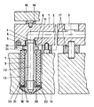
- the drawing shows a vertical partial section through the hot runner distribution system for an injection mold.
- a distributor block 1 contains distributor channels 2, which conduct the heated, plasticized plastic melt, which is supplied, for example, by a heated extruder (not shown), from a central connection 3 to a plurality of outlet openings 4.
- the distributor block 1 is electrically heated by a tubular heater 5.
- a threaded bore 6 is provided, into which a sprue bushing 7 with a threaded attachment 8 is screwed at its upper end.
- Each sprue bushing 7, which is essentially tubular, is surrounded by an electrical heating sleeve 9.
- a cylindrical centering section 10 adjoins the threaded bore 6 in the direction of the sprue bushing 7, into which a centering cylindrical surface 11 on the sprue bushing 7 fits.
- the outlet opening 4 of the distributor channel 2 passes smoothly and without any step or step into a central bore 12 in the sprue bushing 7.
- the sprue bushing 7 is inserted in a receiving bore 13 of a nozzle plate 14 which is arranged at a distance from the distributor block 1 and which part (not shown) forms injection mold.
- a head plate 15 arranged above the distributor block is clamped to the nozzle plate 14 via (lag screws) in such a way that it clamps the distributor block 1 against the nozzle plate 14 via intermediate layers 16, intermediate pieces 17 also being inserted, so that a distance between the distributor block 1 and the nozzle plate 14 remains.
- the sprue bushing 7 carries at its lower end an annular guide disk 18, which is held between the heating sleeve 9 and an inserted nozzle cap 20 of the sprue bushing 7 with the interposition of an insulating disk 19.
- the guide disk 18 forms a circumferential centering surface 21 which is fitted into a cylindrical centering section 22 of the receiving bore 13.
- a certain relative mobility of the free end of the sprue bushing 7 relative to the distributor block 1 is achieved by the predetermined bending point 25.
- the free end of the sprue bushing 7 can be aligned with the centering section 22 in the nozzle plate 14 during assembly of the hot runner distributor system, even if there is a horizontal positional deviation with respect to the outlet opening 4 as a result of manufacturing tolerances.
- this mobility of the sprue bushings 7 means that thermal expansions of the heated distributor block 1 can be permitted transversely to the axis of the sprue bushing 7 (ie in the horizontal direction in the drawing) without a displacement between the upper end of the sprue bushing 7 and the underside of the Distribution block 1 would occur.
- the distributor block 1 with the screwed sprue bushings 7 and the associated electrical installation is completed and checked for electrical functionality. Only then will this unit be delivered to the tool shop. There it is only necessary to do this To connect the unit to the injection mold in such a way that the individual sprue bushings 7 are inserted into the receiving bores 13 of the nozzle plate 4. Electrical wiring or connection work is no longer necessary.
- the heated manifold block 1 Since the heated manifold block 1 is only in contact with neighboring components at a few points, effective thermal insulation is possible in a simple manner; Thermal bridges, which would lead to heating of adjacent components, in particular the injection mold, are largely avoided. Heat-insulating materials can be used for the intermediate pieces 16 or 17 touching the distributor block 1.
- the guide disk 18 also expediently consists of heat-insulating material in order to largely avoid heat transfer between the sprue bushing 7 and the nozzle plate 14.
- the centering of the sprue bushings 7 via the guide disks 18 in the centering sections 22 has the effect that damage to the end face of the nozzle cap 20 is prevented during disassembly.
Landscapes
- Engineering & Computer Science (AREA)
- Manufacturing & Machinery (AREA)
- Mechanical Engineering (AREA)
- Moulds For Moulding Plastics Or The Like (AREA)
- Injection Moulding Of Plastics Or The Like (AREA)
Applications Claiming Priority (2)
| Application Number | Priority Date | Filing Date | Title |
|---|---|---|---|
| DE4028660A DE4028660A1 (de) | 1990-09-10 | 1990-09-10 | Heisskanal-verteilersystem |
| DE4028660 | 1990-09-10 |
Publications (2)
| Publication Number | Publication Date |
|---|---|
| EP0475143A1 true EP0475143A1 (fr) | 1992-03-18 |
| EP0475143B1 EP0475143B1 (fr) | 1995-03-01 |
Family
ID=6413944
Family Applications (1)
| Application Number | Title | Priority Date | Filing Date |
|---|---|---|---|
| EP91114055A Expired - Lifetime EP0475143B1 (fr) | 1990-09-10 | 1991-08-22 | Système de distribution de canaux chauds |
Country Status (3)
| Country | Link |
|---|---|
| US (1) | US5269677A (fr) |
| EP (1) | EP0475143B1 (fr) |
| DE (2) | DE4028660A1 (fr) |
Cited By (5)
| Publication number | Priority date | Publication date | Assignee | Title |
|---|---|---|---|---|
| WO1995002494A1 (fr) * | 1993-07-15 | 1995-01-26 | Stefan Pfaff Werkzeug- Und Formenbau Gmbh & Co. Kg | Bloc pourvu de canaux froids utilise pour le traitement d'elastomeres |
| EP0835732A1 (fr) * | 1996-10-09 | 1998-04-15 | Jobst Ulrich Gellert | Buse de moulage par injection avec bague de guidage et d'étanchéité |
| WO2000018559A1 (fr) * | 1998-09-30 | 2000-04-06 | Gellert Jobst U | Buse de moulage par injection vissee dans la base de montage |
| WO2000023244A1 (fr) * | 1998-10-16 | 2000-04-27 | Gellert Jobst U | Appareil a buse de moulage par injection |
| US6318990B1 (en) | 1998-10-16 | 2001-11-20 | Mold-Masters Limited | Injection molding nozzle apparatus |
Families Citing this family (26)
| Publication number | Priority date | Publication date | Assignee | Title |
|---|---|---|---|---|
| DE4201341C1 (de) * | 1992-01-20 | 1994-01-20 | Incoe Corp | Klemmeinrichtung für Heißkanalverteiler |
| US5536164A (en) * | 1995-05-05 | 1996-07-16 | Electra Form, Inc. | Flexible hot manifold assembly for injection molding machines |
| US5896640A (en) * | 1996-11-12 | 1999-04-27 | Husky Injection Molding Systems Ltd. | Deflection sealing apparatus and method |
| WO1999037461A1 (fr) * | 1998-01-21 | 1999-07-29 | Protool Ag | Manchon mobile distributeur de la matiere plastique fondue permettant de compenser la dilatation thermique entre le canal de carotte chauffe et l'entree du moule |
| US6769901B2 (en) | 2000-04-12 | 2004-08-03 | Mold-Masters Limited | Injection nozzle system for an injection molding machine |
| CA2358148A1 (fr) * | 2001-10-03 | 2003-04-03 | Mold-Masters Limited | Buse d'injection |
| CA2358187A1 (fr) | 2001-10-03 | 2003-04-03 | Mold-Masters Limited | Etancheite pour buse de moulage |
| US6962492B2 (en) | 2001-10-05 | 2005-11-08 | Mold-Masters Limited | Gap seal between nozzle components |
| US7128566B2 (en) | 2002-02-21 | 2006-10-31 | Mold-Masters Limited | Valve pin guiding tip for a nozzle |
| JP2005534534A (ja) | 2002-07-30 | 2005-11-17 | モールド‐マスターズ、リミテッド | 射出成型装置用バルブピン案内・芯合わせシステム |
| CA2450411C (fr) | 2002-11-21 | 2012-01-03 | Mold-Masters Limited | Buse a canaux chauffes avec bec, piece entourant le bec et piece d'alignement |
| DE10356937A1 (de) | 2002-12-09 | 2004-07-15 | Mold-Masters Ltd., Georgetown | Düsenspitze und -dichtung |
| US7306454B2 (en) | 2003-04-07 | 2007-12-11 | Mold-Masters Limited | Front-mountable injection molding nozzle |
| US7179081B2 (en) * | 2003-04-07 | 2007-02-20 | Mold-Masters Limited | Front-mountable, edge-gating nozzle |
| DE602004025755D1 (de) * | 2003-04-07 | 2010-04-08 | Mold Masters 2007 Ltd | Heißkanaldüse mit Schmelzdichtung |
| DE202004005722U1 (de) * | 2004-04-10 | 2004-07-15 | Incoe International, Inc. | Heißkanalverteilerblock für den Anschluß an eine Spritzgießmaschine |
| US7458795B2 (en) * | 2006-02-24 | 2008-12-02 | Incoe Corporation | Co-injection nozzle assembly |
| US7481644B2 (en) * | 2006-03-14 | 2009-01-27 | R & D Tool & Engineering Co. | Universal mounting brackets for attaching a hot injection manifold to the lower die set of an injection blow molding machine |
| US7614869B2 (en) | 2007-05-08 | 2009-11-10 | Mold-Masters (2007) Limited | Manifold nozzle connection for an injection molding system |
| EP2200799A4 (fr) * | 2007-10-22 | 2012-08-29 | Mold Masters 2007 Ltd | Dispositif de moulage par injection |
| DE102008017931A1 (de) | 2008-04-08 | 2009-10-15 | Psg Plastic Service Gmbh | Heißkanaldüse mit anlagefreier Vorzentrierung |
| US7845936B2 (en) * | 2009-01-21 | 2010-12-07 | Mold-Masters (2007) Limited | Sealing arrangement for an edge gated nozzle in an injection molding system |
| US8277213B2 (en) | 2010-12-17 | 2012-10-02 | Dme Company Llc | Apparatus for injection molding |
| TW201429608A (zh) * | 2013-01-18 | 2014-08-01 | Hon Hai Prec Ind Co Ltd | 定位裝置 |
| DE102015116279B3 (de) * | 2015-09-25 | 2017-01-12 | Günther Heisskanaltechnik Gmbh | Spritzgießdüsenvorrichtung |
| ITUB20154577A1 (it) * | 2015-10-12 | 2017-04-12 | Inglass Spa | Iniettore per apparecchiature di stampaggio ad iniezione di materie plastiche e apparecchiatura di stampaggio ad iniezione |
Citations (2)
| Publication number | Priority date | Publication date | Assignee | Title |
|---|---|---|---|---|
| AT367684B (de) * | 1975-10-10 | 1982-07-26 | Flygenring Eduard Freddy | Nadelventil fuer einspritzduesen von heizkanalspritzgiesswerkzeugen |
| DE3837375A1 (de) * | 1987-11-19 | 1989-06-01 | Holdt J W Von | Flexible duese |
Family Cites Families (3)
| Publication number | Priority date | Publication date | Assignee | Title |
|---|---|---|---|---|
| US4266723A (en) * | 1979-11-02 | 1981-05-12 | Incoe Corporation | Nozzle for injection molding machines |
| CA1230458A (fr) * | 1984-07-13 | 1987-12-22 | Gellert, Jobst Ulrich | Buse chauffante de moulage par injection a element chauffant brase et methode de fabrication |
| US5028227A (en) * | 1988-10-31 | 1991-07-02 | Mold-Masters Limited | Injection molding nozzle with replaceable gate insert |
-
1990
- 1990-09-10 DE DE4028660A patent/DE4028660A1/de active Granted
-
1991
- 1991-08-22 DE DE59104761T patent/DE59104761D1/de not_active Expired - Lifetime
- 1991-08-22 EP EP91114055A patent/EP0475143B1/fr not_active Expired - Lifetime
- 1991-08-29 US US07/752,056 patent/US5269677A/en not_active Expired - Lifetime
Patent Citations (2)
| Publication number | Priority date | Publication date | Assignee | Title |
|---|---|---|---|---|
| AT367684B (de) * | 1975-10-10 | 1982-07-26 | Flygenring Eduard Freddy | Nadelventil fuer einspritzduesen von heizkanalspritzgiesswerkzeugen |
| DE3837375A1 (de) * | 1987-11-19 | 1989-06-01 | Holdt J W Von | Flexible duese |
Cited By (6)
| Publication number | Priority date | Publication date | Assignee | Title |
|---|---|---|---|---|
| WO1995002494A1 (fr) * | 1993-07-15 | 1995-01-26 | Stefan Pfaff Werkzeug- Und Formenbau Gmbh & Co. Kg | Bloc pourvu de canaux froids utilise pour le traitement d'elastomeres |
| EP0835732A1 (fr) * | 1996-10-09 | 1998-04-15 | Jobst Ulrich Gellert | Buse de moulage par injection avec bague de guidage et d'étanchéité |
| WO2000018559A1 (fr) * | 1998-09-30 | 2000-04-06 | Gellert Jobst U | Buse de moulage par injection vissee dans la base de montage |
| AU758493B2 (en) * | 1998-09-30 | 2003-03-20 | Jobst Ulrich Gellert | Injection molding nozzle screwed into mounting base |
| WO2000023244A1 (fr) * | 1998-10-16 | 2000-04-27 | Gellert Jobst U | Appareil a buse de moulage par injection |
| US6318990B1 (en) | 1998-10-16 | 2001-11-20 | Mold-Masters Limited | Injection molding nozzle apparatus |
Also Published As
| Publication number | Publication date |
|---|---|
| DE4028660C2 (fr) | 1992-10-01 |
| US5269677A (en) | 1993-12-14 |
| DE59104761D1 (de) | 1995-04-06 |
| EP0475143B1 (fr) | 1995-03-01 |
| DE4028660A1 (de) | 1992-03-26 |
Similar Documents
| Publication | Publication Date | Title |
|---|---|---|
| DE4028660C2 (fr) | ||
| DE69311247T2 (de) | Abgedichtete, seitliche Angussöffnung | |
| DE69218355T2 (de) | Spritzgiessabdichtungsring mit einer zentralen Achse mit heisser Spitze | |
| DE60319637T2 (de) | Mit Gewinde versehenes abnehmbares Heizelement für eine Heisskanal-Düse | |
| DE3403301C2 (fr) | ||
| DE68924706T2 (de) | Spritzgiesssystem mit einer Buchse mit doppelter Zufuhr, montiert im Verteilerkanal. | |
| DE19650326B4 (de) | Spritzgießvorrichtung mit mehreren Düsenspitzen | |
| DE60006653T2 (de) | Vorrichtung und verfahren zum mehrschichtspritzgiessen | |
| DE69106811T2 (de) | Isolierende und elastische Distanzscheibe für Spritzgussformen. | |
| DE3301272C2 (fr) | ||
| DE68905213T2 (de) | Spritzgiesssystem mit duese in tandem. | |
| DE102004017276B4 (de) | Spritzgießvorrichtung mit frontseitig montierbarer Düse mit einem seitlichen Anguss | |
| WO2010003473A2 (fr) | Buse d'injection pour moule d'injection | |
| EP4045267B1 (fr) | Outil de moulage par injection | |
| EP0706447B1 (fr) | Distributeur a canaux chauffants | |
| DE2539785B2 (de) | Heißkanalspritzdüse | |
| EP2633971B1 (fr) | Buse de moulage par injection avec des aiguilles d'obturation guidées par manchon de guidage et dispositif de moulage ainsi équipé | |
| EP0973635B1 (fr) | Manchon distributeur de la matiere plastique fondue | |
| EP0936965B1 (fr) | Filiere de moulage par injection | |
| DE102009021794A1 (de) | Anordnung zum Ausgleich der Wärmedehnung in Heißkanal-Verteileranordnungen von Schmelzeleitsystemen in Spritzgießwerkzeugen | |
| EP0513596B1 (fr) | Distributeur | |
| DE2160535A1 (de) | Heisskanal-spritzgusswerkzeug | |
| DE19522716C1 (de) | Vorrichtung zur Beheizung von Verteilerrohren zum Zuführen von Fluiden | |
| DE19618960B4 (de) | Spritzgießvorrichtung mit verschiebbarer Düse zur Montage von Seitenangussdichtungen | |
| EP2069124B1 (fr) | Élément de remise, en particulier pour une buse d'alimentation de décompression ou une buse de machine de décompression |
Legal Events
| Date | Code | Title | Description |
|---|---|---|---|
| PUAI | Public reference made under article 153(3) epc to a published international application that has entered the european phase |
Free format text: ORIGINAL CODE: 0009012 |
|
| AK | Designated contracting states |
Kind code of ref document: A1 Designated state(s): CH DE FR GB IT LI NL SE |
|
| 17P | Request for examination filed |
Effective date: 19920515 |
|
| 17Q | First examination report despatched |
Effective date: 19930907 |
|
| GRAA | (expected) grant |
Free format text: ORIGINAL CODE: 0009210 |
|
| AK | Designated contracting states |
Kind code of ref document: B1 Designated state(s): CH DE FR GB IT LI NL SE |
|
| PG25 | Lapsed in a contracting state [announced via postgrant information from national office to epo] |
Ref country code: NL Free format text: LAPSE BECAUSE OF NON-PAYMENT OF DUE FEES Effective date: 19950301 |
|
| REF | Corresponds to: |
Ref document number: 59104761 Country of ref document: DE Date of ref document: 19950406 |
|
| ET | Fr: translation filed | ||
| ITF | It: translation for a ep patent filed | ||
| PG25 | Lapsed in a contracting state [announced via postgrant information from national office to epo] |
Ref country code: SE Effective date: 19950601 |
|
| GBT | Gb: translation of ep patent filed (gb section 77(6)(a)/1977) |
Effective date: 19950605 |
|
| NLV1 | Nl: lapsed or annulled due to failure to fulfill the requirements of art. 29p and 29m of the patents act | ||
| PLBE | No opposition filed within time limit |
Free format text: ORIGINAL CODE: 0009261 |
|
| STAA | Information on the status of an ep patent application or granted ep patent |
Free format text: STATUS: NO OPPOSITION FILED WITHIN TIME LIMIT |
|
| 26N | No opposition filed | ||
| REG | Reference to a national code |
Ref country code: CH Ref legal event code: PL |
|
| REG | Reference to a national code |
Ref country code: CH Ref legal event code: AEN Free format text: DAS PATENT IST AUFGRUND DES WEITERBEHANDLUNGSANTRAGES VOM 25.04.1996 WIEDER AKTIVIERT WORDEN. |
|
| REG | Reference to a national code |
Ref country code: CH Ref legal event code: NV Representative=s name: SCHAAD, BALASS & PARTNER AG |
|
| REG | Reference to a national code |
Ref country code: GB Ref legal event code: IF02 |
|
| PGFP | Annual fee paid to national office [announced via postgrant information from national office to epo] |
Ref country code: CH Payment date: 20100823 Year of fee payment: 20 |
|
| PGFP | Annual fee paid to national office [announced via postgrant information from national office to epo] |
Ref country code: FR Payment date: 20100728 Year of fee payment: 20 Ref country code: IT Payment date: 20100812 Year of fee payment: 20 |
|
| PGFP | Annual fee paid to national office [announced via postgrant information from national office to epo] |
Ref country code: GB Payment date: 20100826 Year of fee payment: 20 |
|
| PGFP | Annual fee paid to national office [announced via postgrant information from national office to epo] |
Ref country code: DE Payment date: 20100921 Year of fee payment: 20 |
|
| REG | Reference to a national code |
Ref country code: DE Ref legal event code: R071 Ref document number: 59104761 Country of ref document: DE |
|
| REG | Reference to a national code |
Ref country code: DE Ref legal event code: R071 Ref document number: 59104761 Country of ref document: DE |
|
| REG | Reference to a national code |
Ref country code: CH Ref legal event code: PL |
|
| PG25 | Lapsed in a contracting state [announced via postgrant information from national office to epo] |
Ref country code: GB Free format text: LAPSE BECAUSE OF EXPIRATION OF PROTECTION Effective date: 20110821 |
|
| PG25 | Lapsed in a contracting state [announced via postgrant information from national office to epo] |
Ref country code: DE Free format text: LAPSE BECAUSE OF EXPIRATION OF PROTECTION Effective date: 20110823 |