EP0475202B1 - Dispositif pour plier des produits hygiéniques - Google Patents
Dispositif pour plier des produits hygiéniques Download PDFInfo
- Publication number
- EP0475202B1 EP0475202B1 EP91114497A EP91114497A EP0475202B1 EP 0475202 B1 EP0475202 B1 EP 0475202B1 EP 91114497 A EP91114497 A EP 91114497A EP 91114497 A EP91114497 A EP 91114497A EP 0475202 B1 EP0475202 B1 EP 0475202B1
- Authority
- EP
- European Patent Office
- Prior art keywords
- folding
- gear
- thrust member
- planet gear
- sun gear
- Prior art date
- Legal status (The legal status is an assumption and is not a legal conclusion. Google has not performed a legal analysis and makes no representation as to the accuracy of the status listed.)
- Expired - Lifetime
Links
- RNLLROGAQGGIRL-UHFFFAOYSA-N CC(C1CCCC(C)CCCCC1)N Chemical compound CC(C1CCCC(C)CCCCC1)N RNLLROGAQGGIRL-UHFFFAOYSA-N 0.000 description 1
Images


Classifications
-
- B—PERFORMING OPERATIONS; TRANSPORTING
- B65—CONVEYING; PACKING; STORING; HANDLING THIN OR FILAMENTARY MATERIAL
- B65H—HANDLING THIN OR FILAMENTARY MATERIAL, e.g. SHEETS, WEBS, CABLES
- B65H45/00—Folding thin material
- B65H45/12—Folding articles or webs with application of pressure to define or form crease lines
- B65H45/16—Rotary folders
- B65H45/161—Flying tuck folders
-
- A—HUMAN NECESSITIES
- A61—MEDICAL OR VETERINARY SCIENCE; HYGIENE
- A61F—FILTERS IMPLANTABLE INTO BLOOD VESSELS; PROSTHESES; DEVICES PROVIDING PATENCY TO, OR PREVENTING COLLAPSING OF, TUBULAR STRUCTURES OF THE BODY, e.g. STENTS; ORTHOPAEDIC, NURSING OR CONTRACEPTIVE DEVICES; FOMENTATION; TREATMENT OR PROTECTION OF EYES OR EARS; BANDAGES, DRESSINGS OR ABSORBENT PADS; FIRST-AID KITS
- A61F13/00—Bandages or dressings; Absorbent pads
- A61F13/15—Absorbent pads, e.g. sanitary towels, swabs or tampons for external or internal application to the body; Supporting or fastening means therefor; Tampon applicators
- A61F13/15577—Apparatus or processes for manufacturing
- A61F13/15707—Mechanical treatment, e.g. notching, twisting, compressing, shaping
- A61F13/15747—Folding; Pleating; Coiling; Stacking; Packaging
Definitions
- the invention relates to a device for folding hygiene products and in particular soft, elongated parts of small thickness such as diaper pants etc. and comprises features according to the preamble of patent claim 1.
- a device of the type mentioned is known from US-A-3,337, 211 and comprises folding plungers which hit the moving, elongated part at the folding point and fold it transversely to its direction of movement in the plunger direction into a receptacle or into a gap .
- a gear in the form of a gear drive is provided as a drive for the folding plunger and comprises a stationary sun gear, which is mounted on an axis between the frame walls and in the interior of a deflection and folding drum rotatably mounted on the axis.
- the gear transmission serving as the drive further comprises an intermediate gear and a planet gear controlling the tappet.
- sprockets are provided at both ends of the deflection and folding drum and set them in rotation.
- the stationary sun wheel is not arranged on an axle supporting the deflection and folding drum, but on a frame wall and the folding plunger is not moved relative to the stationary sun wheel with the help of the rotating deflection and folding drum, but with the aid of its own drive and a shaft , which is also rotatably mounted in the frame wall.
- the folding plunger thus has a direct and direct drive and not an indirect drive as in the device according to US-A-3,337,211.
- the drive and the storage of the gear parts required for the movement of the folding plunger is simpler and less complex than before and thus allow higher speeds.
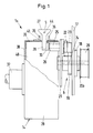
- the invention is described below with reference to an embodiment shown in the drawing. Show: The working speed of the known folding devices is fundamentally high, but it still does not meet the requirements in all cases. In particular, since the other components of the production machines could be operated at higher hourly outputs, the folding devices represent a bottleneck that has a decisive influence on the operating speed of the overall system.
- two devices 1 and 1a belong to a folding station 9.
- the second device 1 a also has two conveyor belts 10 and 11 running around deflection rollers to form the gap 4. Further conveyor belts 12 and 13 are provided in order to first feed the part 2 to be folded to the first device 1 before the conveyor belts 7 and 8 forming the first receiving gap 4 perpendicular to it feed the once folded part 2a to a deflection and folding drum 14 of the second folding device 1a . There the second folding takes place, so that the ends 15 and 16 of part 2a lie one on top of the other.
- the drive for the two devices 1 and 1a according to Figures 1 and 2 is a gear transmission in the form of a planetary gear-like transmission 6. It comprises a stationary sun gear 19 adjustable on a frame wall 17 with the aid of an adjustable support plate 18 and one on a likewise in the Frame wall 17 rotatably mounted shaft 20a and driven by a drive wheel 20 carrier 21 for a planet gear 22 and for an intermediate gear 23 which meshes with the sun gear 19 on the one hand and with the planet gear 22 on the other hand.
- the carrier 21 can be disc-shaped.
- the number of teeth of the planet gear 22 to the number of teeth of the sun gear 19 is 1: 2.
- the number of teeth of the intermediate gear 23 is any. Therefore, when the drive gear 20 rotates the carrier 21 via the shaft 20a, the planet gear 22 and the idler gear 23 orbit the stationary sun gear 19, and further the planet gear 22 makes a counterclockwise rotation when the carrier 21 rotates in the opposite direction.
- the planet gear 22 which does not mesh with the sun gear 19 is arranged axially offset from the sun gear 19 and laterally next to the intermediate gear 23 with respect to the orbit.
- the intermediate gear 23 meshing with the planet gear 22 and the sun gear 19 has a width which is equal to the width of the sun gear 19 and the planet gear 22. This makes it possible to arrange the planet gear 22 and the intermediate gear 23 close to the shaft 20a or to the axis 24 of the sun gear 19.
- the folding plunger 5 is freely rotatable about an arm 25 and is controlled by the planet gear 22.
- the arm 25 is a shaft rotatably mounted in the carrier 21, which connects the planet gear 22 to the folding plunger 5 and transmits the rotational movement of the planet gear 22 to the folding plunger 5.
- a bushing 26 serves to support the shaft 25 with the planet gear 22 and the folding plunger 5 on the carrier 21.
- the planet gear 22 moves with its axis of rotation 29 clockwise on a radius R in the direction of arrow a around the axis 24 of the sun gear 19, then the planet gear 22 rotates counterclockwise because of the intermediate gear 23 arrow b. Due to the preferably used transmission ratio of 2: 1 between sun gear 19 and planet gear 22, the planet gear 22 rotates counterclockwise by the same angular amount by which it moves clockwise around the sun gear. This has the consequence that a folding tappet 5 controlled by the planet gear 22 executes a full counterclockwise rotation when the planet gear 22 is fully rotated, which is additionally superimposed on the rotational movement of the planet gear 22.
- the plunger 5 tilts from the position I corresponding to its highest folding position when retracting first to the left according to the position II and then further into the position III according to FIG. 7 until it reaches the most retracted position IV, where the free end 27 of the plunger 5 in the opposite direction to that of the position I.
- the folding plunger 5 then lifts again, passes through the position V and, approximately in the position VI, meets the part 2 to be folded.
- the position VI in FIG. 7 corresponds to one when the folding plunger is withdrawn from the position I. Position in mirror image to the right of the movement axis 30, not shown in FIG.
- the folding plunger 5 defines itself and also with its free end 27 and its shaft-side end 28 in the area of the folding point 3 during the forward movement and during the backward movement an envelope curve 31, which is partially shown in FIG. 5.
- This envelope curve 31 shows that the plunger 5 not only exerts changing forces on the part 2 transversely to the transport direction c of the part 2 to be folded, but also in the transport direction c, because it moves from the position VI on the left at the beginning of the folding process into the Position VII (Fig. 5) moved to the right of the movement axis 30 at the end of the folding process.
- the envelope curve 31 in FIG. 5 shows the sequence of movements in the case of a folding plunger 5 which is symmetrical about the movement axis 30.
- FIG. 6 shows an envelope curve 32 of an asymmetrically effective folding plunger 5. The asymmetrical enveloping curve 32 is achieved when the folding plunger 5 is arranged on the arm 25 carrying it, not in the center but rather off-center.
- a symmetrically effective arrangement of the folding plunger 5 with an envelope 31 according to FIG. 5 is advantageous if the folding plunger 5 has a first fold on an elongated part 2 according to FIG. 2 in the first device 1 of the folding station 9.
- the asymmetrically effective envelope curve 32 and the eccentric arrangement of the folding plunger 5 are particularly suitable for the production of the second folding in the device 1a of the folding station 9, because here the folding plunger 5 should not only press the part 2a that has already been folded into the gap-shaped receptacle 3 , but also prevent the already pre-folded end 15 from opening again and being torn out of the folded part 2 when the folding plunger 5 is pulled back.
- the plunger 5 can be attached with its shaft-side end 28 to the shaft 25 with the aid of an intermediate piece 33 either symmetrically according to FIG. 5, or assume a leading position according to FIG. 6 and also receive a trailing position according to a fastening form (not shown).
- the plunger 5 In the leading position acc. 6, the plunger 5 reaches position I in FIG. 7 even before the axis of rotation 29 of the planet gear 22 intersects the axis of movement 30.
- the folding plunger 5 is arranged eccentrically on the shaft 25 in such a way that the axis of rotation 29 of the planet gear 22 and the shaft 25 leads and has already exceeded the movement axis 30 before the folding plunger 5 is in alignment with the movement axis 30 or one with it parallel position reached.
- the plunger 5 can therefore be adjusted so that it performs optimal movements according to the respective requirements.
- the distance A from the axis of rotation 29 of the planet gear 22 or the shaft 25 to the free end 27 of the folding plunger 5 is as great as the distance B from the axis of rotation 29 of the planet gear 22 to the axis 24 of the sun gear 19. Then the free end 27 of the folding plunger 5 moves in a symmetrical arrangement to the axis 29 along the movement axis 30, while the planet gear 22 performs a revolution.
- the device 1 a in the folding station 9 according to FIG. 2 additionally has a deflecting and folding drum 14 compared to the device 1, on the circumference 34 of which the part 2 a coming from the device 1 leads with its fold 35 leading.
- the deflection and folding drum 14 has finger-like holding elements 36 arranged in pairs offset in the circumferential direction.
- the conveyor belts 7 and 8 each push the parts 2a between the finger-like holding elements 36 and the circumference 34 of the deflection and folding drum 14.
- the deflection and folding drum 14 sits cantilevered on a drive shaft 37 and consists of a drum base 38 and a cylindrical wall 39 which is open to the gear 6 (Fig. 1).
- the folding plunger 5 extends at right angles from the arm 25 or is radial or substantially radial to the axis of rotation 29 of the planet gear 22.
- One passage opening 41 is assigned to each group of finger-like holding elements 36 on the circumference 34 of the deflection and folding drum 14. As shown in FIG. 4, there is in each case a passage opening 41 behind the finger-like holding elements 36 holding the part 2a that has been folded once.
- the passage openings 41 have projections 42 facing one another over half the length and a recess 43 facing the finger-like holding elements 36
- a small opening area is desirable in order to prevent dust and the like from entering the interior 40 of the deflection and folding drum 14.
- the device 1 works with its plunger 5 vertically upwards, so that the free end 27 of the plunger 5 moves along the movement axis 30 which is perpendicular in FIG. 2.
- the folding plunger 5 works horizontally and moves with its free end along the horizontal axis of movement 30. Only shown in broken lines and designated 5a, the folding plunger together with the planet gear and the idler gear in FIG. 2 in position IV according to FIG. Fig. 7, that is, when half an orbit is reached, when the free end 27 of the plunger 5 has moved the furthest away from the folding point 3.
- the deflection and folding drum 14 is a folding plunger 5 and essential parts of its drive receiving and protecting housing.
- compressed air can also be effective laterally at the free end 27 for support.
- a blowing nozzle 44 is located laterally at the free end 27 of the folding plunger 5 and is connected in a suitable manner, not shown in the figures, to a compressed air generator and a control device.
- a resilient pressure piece can also be arranged laterally at the free end 27 of the folding plunger 5 in order to generate the desired lateral pressures and forces.
Landscapes
- Health & Medical Sciences (AREA)
- Engineering & Computer Science (AREA)
- Life Sciences & Earth Sciences (AREA)
- Animal Behavior & Ethology (AREA)
- Epidemiology (AREA)
- Biomedical Technology (AREA)
- Heart & Thoracic Surgery (AREA)
- Vascular Medicine (AREA)
- Mechanical Engineering (AREA)
- Manufacturing & Machinery (AREA)
- General Health & Medical Sciences (AREA)
- Public Health (AREA)
- Veterinary Medicine (AREA)
- Folding Of Thin Sheet-Like Materials, Special Discharging Devices, And Others (AREA)
- Absorbent Articles And Supports Therefor (AREA)
- Auxiliary Devices For And Details Of Packaging Control (AREA)
Claims (15)
- Dispositif pour le pliage de produits hygiéniques et en particulier de pièces (2) molles allongées et de faible épaisseur comme par exemple des couches-culottes, des serviettes hygiéniques etc., un poussoir de pliage (5, 5a) étant prévu qui, à la pliure (3), se dirige vers la pièce allongée (2) mobile et la pousse, transversalement à son sens de déplacement, dans un logement (4) respectivement dans une fente (4) en la pliant dans le sens du poussoir, de plus un engrenage (6) sous forme d'un engrenage à roue dentée étant prévu pour l entraînement du poussoir de pliage (5), engrenage qui présente une roue planétaire stationnaire (19), une roue intermédiaire (23) et une roue satellite (22) commandant le poussoir de pliage (5), caractérisé en ce que la roue planétaire stationnaire (19) est disposée contre une paroi de bâti (17), et en ce qu'un arbre mené (20a) est logé rotatif dans la paroi de bâti (17) et en ce que sur l'arbre (20a) est disposé un support (21) pour la roue satellite (22) et pour la roue intermédiaire (23), la roue intermédiaire venant en prise d'une part, avec la roue planétaire (19) et, d'autre part, avec la roue satellite (22), et en ce que le poussoir de pliage (5, 5a) est monté librement rotatif sur un support (21) autour d'un bras (25) et est commandé par la roue satellite (22).
- Dispositif selon la revendication 1, caractérisé en ce qu'un arbre logé rotatif dans le support 21 fait office de bras (25).
- Dispositif selon la revendication 1 et 2, caractérisé en ce qu'une roue menante (20) est prévue pour l'entraînement de l'arbre (20a) et en ce que le support (21) est en forme de disque.
- Dispositif selon l'une ou plusieurs des revendications précédentes, caractérisé en ce que le rapport entre le nombre de dents de la roue satellite (22) et le nombre de dents de la roue planétaire (19) est de 1:2.
- Dispositif selon l'une ou plusieurs des revendications précédentes caractérisé en ce que la roue satellite (22) qui n'est pas en prise avec la roue planétaire (19), est décalée latéralement à côté de la roue intermédiaire (23) et, ce, axialement par rapport à la roue planétaire (19) et à l'orbite, la roue intermédiaire (23), qui vient en prise avec la roue satellite (22) et avec la roue planétaire (19), présentant une largeur égale à la largeur de la roue planétaire (19) et de la roue satellite (22).
- Dispositif selon l'une ou plusieurs des revendications précédentes, caractérisé en ce que la distance (A) entre l'axe de rotation (29) de la roue satellite (22) respectivement de l'arbre (25) et l'extrémité libre (27) du poussoir de pliage (5) est égale à la distance (B) entre l'axe de rotation (29) de la roue satellite (22) et l'axe (24) de la roue planétaire (19).
- Dispositif selon l'une ou plusieurs des revendications précédentes caractérisé en ce qu'un tambour de pliage et de renvoi (14) est disposé en porte à faux sur un autre arbre menant (37) et s'ouvre sur l'engrenage (6) en entourant celui-ci.
- Dispositif selon l'une ou plusieurs des revendications précédentes, caractérisé en ce que le tambour de pliage et de renvoi se compose d'un fond de tambour (38) et d'une paroi cylindrique (39) qui présente au moins une ouverture de passage (41) pour la traversée de l'extrémité libre (27) du poussoir de pliage (5).
- Dispositif selon l'une ou plusieurs des revendications précédentes, caractérisé en ce que des éléments de retenue (36) en forme de doigts sont disposés sur la périphérie (34) du tambour de pliage et de renvoi (14).
- Dispositif selon l'une ou plusieurs des revendications précédentes caractérisé en ce que chaque ouverture de passage (41) se situe dans le sens de la marche derrière les éléments de retenue (36) en forme de doigts maintenant la pièce (2a).
- Dispositif selon l'une ou plusieurs des revendications précédentes, caractérisé en ce que le poussoir de pliage (5) présente la forme d'un T.
- Dispositif selon l'une ou plusieurs des revendications précédentes, caractérisé en ce qu'une buse (44) de soufflage d'air comprimé est disposée à l'extrémité du poussoir de pliage (5).
- Dispositif selon l'une ou plusieurs des revendications précédentes caractérisé en ce que la roue planétaire stationnaire (19) peut être disposée, de manière réglable, contre la paroi de bâti (17) à l'aide d'une plaque-support (18) ajustable.
- Dispositif selon l'une ou plusieurs des revendications précédentes, caractérisé en ce que le poussoir de pliage (5) est disposé de manière excentrée sur son bras de support (25).
- Dispositif selon l'une ou plusieurs des revendications précédentes, caractérisé en ce que, pour le pliage d'une pièce (2) pliée plusieurs fois, un premier dispositif (1) est disposé de manière à avoir son poussoir de pliage (5) travaillant à la verticale vers le haut, tandis que le poussoir de pliage (5) d'un second dispositif (1a) se déplace horizontalement pour la seconde opération de pliage.
Applications Claiming Priority (2)
| Application Number | Priority Date | Filing Date | Title |
|---|---|---|---|
| DE4028889 | 1990-09-12 | ||
| DE4028889A DE4028889A1 (de) | 1990-09-12 | 1990-09-12 | Verfahren und vorrichtung zum falten von hygieneprodukten |
Publications (2)
| Publication Number | Publication Date |
|---|---|
| EP0475202A1 EP0475202A1 (fr) | 1992-03-18 |
| EP0475202B1 true EP0475202B1 (fr) | 1995-06-07 |
Family
ID=6414081
Family Applications (1)
| Application Number | Title | Priority Date | Filing Date |
|---|---|---|---|
| EP91114497A Expired - Lifetime EP0475202B1 (fr) | 1990-09-12 | 1991-08-29 | Dispositif pour plier des produits hygiéniques |
Country Status (4)
| Country | Link |
|---|---|
| US (1) | US5176615A (fr) |
| EP (1) | EP0475202B1 (fr) |
| JP (1) | JP3037480B2 (fr) |
| DE (2) | DE4028889A1 (fr) |
Cited By (1)
| Publication number | Priority date | Publication date | Assignee | Title |
|---|---|---|---|---|
| US7384386B2 (en) | 2005-12-01 | 2008-06-10 | Kimberly-Clark Worldwide, Inc. | Method and apparatus for folding articles |
Families Citing this family (34)
| Publication number | Priority date | Publication date | Assignee | Title |
|---|---|---|---|---|
| DE4141143A1 (de) * | 1991-12-13 | 1993-06-17 | Winkler Duennebier Kg Masch | Vorrichtung zum falten und verpacken von hygieneprodukten |
| DE59804551D1 (de) * | 1997-03-24 | 2002-08-01 | Grapha Holding Ag | Schwertfalzmaschine und Verfahren zum Querfalzen von Bogen mit einer Schwertfalzmaschine sowie Akzidenzverarbeitungslinie mit einer solchen Schwertfalzmaschine |
| US6015934A (en) * | 1997-11-12 | 2000-01-18 | Kimberly-Clark Worldwide, Inc. | Individually wrapped absorbent article and method and apparatus for its production |
| JP2001522643A (ja) | 1997-11-12 | 2001-11-20 | キンバリー クラーク ワールドワイド インコーポレイテッド | 個別包装された吸収性物品と同物品を製造するための装置及び方法 |
| US6283905B1 (en) * | 1999-08-31 | 2001-09-04 | Ethicon | System and method for producing folded articles |
| US6481362B2 (en) | 2000-05-16 | 2002-11-19 | Kimberly-Clark Worldwide, Inc. | Orbital motion device for seaming garments |
| US6497032B2 (en) * | 2000-05-16 | 2002-12-24 | Kimberly-Clark Worldwide, Inc. | Refastenable bonding of garment side panels |
| US6565691B2 (en) | 2000-05-16 | 2003-05-20 | Kimberly-Clark Worldwide, Inc. | Method and apparatus for forming a lap seam |
| US6513221B2 (en) | 2000-05-16 | 2003-02-04 | Kimberly-Clark Worldwide, Inc. | Garment side panel conveyor system and method |
| US6562167B2 (en) * | 2000-05-16 | 2003-05-13 | Kimberly-Clark Worldwide, Inc. | Methods for making garments with fastening components |
| US6846374B2 (en) | 2000-05-16 | 2005-01-25 | Kimberly-Clark Worldwide | Method and apparatus for making prefastened and refastenable pant with desired waist and hip fit |
| US6596113B2 (en) | 2000-05-16 | 2003-07-22 | Kimberly-Clark Worldwide, Inc. | Presentation and bonding of garment side panels |
| MXPA02011282A (es) * | 2000-05-16 | 2003-04-25 | Kimberly Clark Co | Doblado y fabricacion de calzoncillos desechables de aprendizaje. |
| US6723034B2 (en) | 2000-05-16 | 2004-04-20 | Kimberly-Clark Worldwide, Inc. | Presentation of fastening components for making prefastened and refastenable pants |
| US6514187B2 (en) * | 2000-05-16 | 2003-02-04 | Kimberly-Clark Worldwide, Inc. | Folding and manufacture of pants |
| US7387148B2 (en) | 2001-05-15 | 2008-06-17 | Kimberly-Clark Worldwide, Inc. | Garment side panel conveyor system and method |
| US6589150B1 (en) * | 2000-09-05 | 2003-07-08 | Mcneil-Ppc, Inc. | Apparatus and method to fold and secure sanitary napkin flaps prior to packaging |
| DE10143042A1 (de) * | 2000-09-08 | 2002-05-02 | Heidelberger Druckmasch Ag | Vorrichtung zum Falzen von Druckexemplaren |
| DE10160101C1 (de) * | 2001-12-07 | 2003-07-03 | Koenig & Bauer Ag | Räderfalzapparat |
| US7322925B2 (en) * | 2005-12-15 | 2008-01-29 | Kimberly-Clark Worldwide, Inc. | Apparatus and method for making pre-fastened absorbent undergarments |
| US7335150B2 (en) * | 2005-12-15 | 2008-02-26 | Kimberly-Clark Worldwide, Inc. | Apparatus for making pre-fastened absorbent undergarments |
| DE102010018359A1 (de) | 2010-04-26 | 2011-10-27 | WINKLER + DüNNEBIER AG | Faltvorrichtung für Hygieneprodukte |
| IT1403200B1 (it) * | 2010-12-23 | 2013-10-15 | Gdm Spa | Metodo ed unità di piegatura di assorbenti igienici. |
| WO2012123813A1 (fr) * | 2011-03-17 | 2012-09-20 | Fameccanica.Data Spa | Procédé et équipement permettant de plier une couche-culotte |
| US9918881B2 (en) | 2011-11-22 | 2018-03-20 | Kimberly-Clark Worldwide, Inc. | Method of folding pant-like disposable absorbent garments in a trough |
| US11123230B2 (en) | 2011-11-22 | 2021-09-21 | Kimberly-Clark Worldwide, Inc. | Method of folding pant-like disposable absorbent garments in a chute |
| US10118754B2 (en) | 2011-11-22 | 2018-11-06 | Kimberly-Clark Worldwide, Inc. | Method of folding pant-like disposable absorbent garments in a chute |
| JP5969862B2 (ja) * | 2012-08-30 | 2016-08-17 | ユニ・チャーム株式会社 | 吸収性物品の折り畳み装置 |
| US9764905B2 (en) * | 2012-10-23 | 2017-09-19 | The Procter & Gamble Plaza | Method and apparatus for advancing an absorbent article |
| CN107074476A (zh) * | 2014-06-30 | 2017-08-18 | 宝洁公司 | 用于折叠吸收制品的方法 |
| CN104787370B (zh) * | 2015-04-01 | 2018-10-02 | 金湖三木机械制造实业有限公司 | 卫生用品自动分堆计数装箱装置 |
| CN108082622B (zh) * | 2018-01-12 | 2023-08-08 | 广州市兴世机械制造有限公司 | 一种平片产品的折叠装置与方法 |
| US12004928B2 (en) * | 2019-04-12 | 2024-06-11 | Zuiko (Shanghai) Corporation | Folding device for disposable hygiene article |
| CN110745317A (zh) * | 2019-09-10 | 2020-02-04 | 松嘉(泉州)机械有限公司 | 一种卫生巾同步带用三折叠装置 |
Citations (1)
| Publication number | Priority date | Publication date | Assignee | Title |
|---|---|---|---|---|
| US1481252A (en) * | 1922-02-20 | 1924-01-22 | Paper Converting Machine Co | Sheet-folding machine |
Family Cites Families (28)
| Publication number | Priority date | Publication date | Assignee | Title |
|---|---|---|---|---|
| US879510A (en) * | 1907-05-14 | 1908-02-18 | Duplex Printing Press Co | Folding mechanism for printing-presses. |
| FR412368A (fr) * | 1910-02-07 | 1910-07-11 | Duplex Printing Press Co | Mécanisme rotatif pour le pliage des journaux, et autres imprimés, à grande vitesse |
| US1482252A (en) * | 1922-04-17 | 1924-01-29 | George W Smith & Company Inc | Wood disk wheel |
| US1684901A (en) * | 1922-08-08 | 1928-09-18 | Wood Newspaper Mach Corp | Folder |
| US1536581A (en) * | 1923-01-15 | 1925-05-05 | Hoe & Co R | Folding mechanism |
| GB225306A (en) * | 1923-09-04 | 1924-12-04 | Goss Printing Press Co Ltd | Improvements in folding mechanism for printing presses or the like |
| US1578436A (en) * | 1924-05-12 | 1926-03-30 | R Hoe And Co Inc | Sheet-control mechanism |
| GB255352A (en) * | 1926-02-18 | 1926-07-22 | Hoe & Co R | Improvements in and relating to paper folding mechanism |
| GB535717A (en) * | 1939-11-09 | 1941-04-18 | Cecil George Quick | Improvements in or relating to rotary folding mechanism |
| US2981540A (en) * | 1958-04-21 | 1961-04-25 | Hoe & Co R | Printing machine folding mechanism |
| DE1246767B (de) * | 1965-01-04 | 1967-08-10 | Plamag Plauener Druckmaschinen | Falz- und Sammelvorrichtung fuer Rotationsdruckmaschinen |
| US3337211A (en) * | 1965-07-23 | 1967-08-22 | Johnson & Johnson | Apparatus for continuously folding and cutting off web material |
| US3517920A (en) * | 1967-04-13 | 1970-06-30 | Wood Newspaper Mach Corp | Folding blade silencing mechanism |
| DE1811840C3 (de) * | 1967-11-30 | 1975-07-17 | Daikin Kogyo Co. Ltd., Osaka (Japan) | Verfahren zur Herstellung von Trifluoressigsäure und 1,1,1-Trifluor-2,2dichloräthan |
| US3578311A (en) * | 1969-05-29 | 1971-05-11 | Cities Service Co | Folding method and apparatus therefor |
| US3685820A (en) * | 1970-04-13 | 1972-08-22 | Linotype Machinery Ltd | Printing press folders |
| US3752470A (en) * | 1970-12-01 | 1973-08-14 | Ametek Inc | Single operator sheet folder |
| DE2242577A1 (de) * | 1972-08-30 | 1974-03-07 | Will E C H Fa | Vorrichtung zum klammern und falten mehrerer uebereinanderliegender papierbogen |
| US3994486A (en) * | 1973-10-05 | 1976-11-30 | Paper Converting Machine Company | Diaper folding apparatus |
| IT1032212B (it) * | 1974-10-21 | 1979-05-30 | Paper Converting Machine Co | Dispositive per piegare pannolini per neonati |
| US3973373A (en) * | 1975-03-10 | 1976-08-10 | Colgate-Palmolive Company | Automatic packaging method and apparatus |
| US4053150A (en) * | 1976-03-08 | 1977-10-11 | Cornelius Printing Co. | Folder apparatus |
| FR2426004A1 (fr) * | 1978-05-19 | 1979-12-14 | Giovannini Michel | Machine pour plier les plans au format |
| DE3528634A1 (de) * | 1985-08-09 | 1987-02-12 | Buehler Optima Maschf | Vorrichtung zum verpacken von einzelnen gegenstaenden |
| DE3614984A1 (de) * | 1985-08-09 | 1987-11-05 | Buehler Optima Maschf | Vorrichtung in einer automatischen verpackungsanlage |
| SE451261B (sv) * | 1986-01-08 | 1987-09-21 | Mo Och Domsjoe Ab | Anordning for att dubbelvika en flexibel produkt |
| JP6132401B2 (ja) | 2013-08-29 | 2017-05-24 | 香蘭産業株式会社 | 燻し焼き装置の空気導入機構 |
| JP6150868B2 (ja) | 2015-11-11 | 2017-06-21 | 株式会社大一商会 | 遊技機 |
-
1990
- 1990-09-12 DE DE4028889A patent/DE4028889A1/de not_active Withdrawn
-
1991
- 1991-08-29 EP EP91114497A patent/EP0475202B1/fr not_active Expired - Lifetime
- 1991-08-29 DE DE59105654T patent/DE59105654D1/de not_active Expired - Lifetime
- 1991-09-10 JP JP3258369A patent/JP3037480B2/ja not_active Expired - Fee Related
- 1991-09-10 US US07/757,674 patent/US5176615A/en not_active Expired - Lifetime
Patent Citations (1)
| Publication number | Priority date | Publication date | Assignee | Title |
|---|---|---|---|---|
| US1481252A (en) * | 1922-02-20 | 1924-01-22 | Paper Converting Machine Co | Sheet-folding machine |
Cited By (1)
| Publication number | Priority date | Publication date | Assignee | Title |
|---|---|---|---|---|
| US7384386B2 (en) | 2005-12-01 | 2008-06-10 | Kimberly-Clark Worldwide, Inc. | Method and apparatus for folding articles |
Also Published As
| Publication number | Publication date |
|---|---|
| JPH04266360A (ja) | 1992-09-22 |
| JP3037480B2 (ja) | 2000-04-24 |
| EP0475202A1 (fr) | 1992-03-18 |
| DE59105654D1 (de) | 1995-07-13 |
| US5176615A (en) | 1993-01-05 |
| DE4028889A1 (de) | 1992-03-19 |
Similar Documents
| Publication | Publication Date | Title |
|---|---|---|
| EP0475202B1 (fr) | Dispositif pour plier des produits hygiéniques | |
| DE69205994T2 (de) | Beutelherstellungs-, -füll- und -siegelvorrichtung sowie verfahren für einen weiten beutelgrössenbereich. | |
| DE3141364C2 (de) | Vorrichtung zum Verteilen von aufrechtstehenden Gefäßen | |
| DE3141431C2 (de) | Vorrichtung zum Herstellen, Füllen und Verschließen von Beuteln | |
| DE4426987C2 (de) | Falzapparat mit Formatumstellung | |
| DE69105248T2 (de) | Vorrichtung zum Versiegeln für eine Maschine zum Formen, Füllen und Schliessen von Packungen. | |
| CH616375A5 (fr) | ||
| DE3610010A1 (de) | Vorrichtung zum abteilen von portionspackungen eines unterteilbaren fuellgutes in einer flexiblen schlauchhuelle | |
| DE69405667T2 (de) | Vorrichtung mit einem Verpackungsrad zum Zuführen von Hüllen, insbesondere in Zigaretten-Verpackungsmaschinen | |
| EP0659670A1 (fr) | Plieuse à lames engageantes pour machine rotative d'impression | |
| DE2604729A1 (de) | Verfahren und maschine zur schrumpf- folien-verpackung | |
| DE3436616C2 (fr) | ||
| EP1437318B1 (fr) | Dispositif de pliage comportant un cylindre à circonférence variable | |
| CH688375A5 (de) | Einrichtung zum Verarbeiten von Druckereiprodukten. | |
| DD202242A5 (de) | Verfahren und einrichtung zum transport von zigaretten | |
| DE2908159C2 (fr) | ||
| DE69901634T2 (de) | Getriebe für Produkt Förderer | |
| EP0999161B1 (fr) | Dispositif pour compenser le mouvement d'avance d'une bande de film | |
| EP0080519B1 (fr) | Procédé et machine pour plier des affiches | |
| AT407236B (de) | Vorrichtung zur trennung übereinanderliegender materialbahnen | |
| DE69007742T2 (de) | Gelenkgetriebe für den gleichzeitigen und synchronen Antrieb der Zufuhrvorrichtung und einer Station zum automatischen Umhüllen von Obst- oder Gemüse-Behältern mit einem Netz. | |
| DE3613117C2 (de) | Faltvorrichtung | |
| DE3613859C2 (fr) | ||
| DE4344621C2 (de) | Einrichtung zum Einstellen eines Räderfalzapparates | |
| DE2703462C2 (de) | Vorrichtung zur Herstellung seitengeschweißter Flachbeutel |
Legal Events
| Date | Code | Title | Description |
|---|---|---|---|
| PUAI | Public reference made under article 153(3) epc to a published international application that has entered the european phase |
Free format text: ORIGINAL CODE: 0009012 |
|
| AK | Designated contracting states |
Kind code of ref document: A1 Designated state(s): DE FR IT SE |
|
| 17P | Request for examination filed |
Effective date: 19920429 |
|
| 17Q | First examination report despatched |
Effective date: 19940119 |
|
| GRAA | (expected) grant |
Free format text: ORIGINAL CODE: 0009210 |
|
| AK | Designated contracting states |
Kind code of ref document: B1 Designated state(s): DE FR IT SE |
|
| REF | Corresponds to: |
Ref document number: 59105654 Country of ref document: DE Date of ref document: 19950713 |
|
| ET | Fr: translation filed | ||
| ITF | It: translation for a ep patent filed | ||
| PLBE | No opposition filed within time limit |
Free format text: ORIGINAL CODE: 0009261 |
|
| STAA | Information on the status of an ep patent application or granted ep patent |
Free format text: STATUS: NO OPPOSITION FILED WITHIN TIME LIMIT |
|
| 26N | No opposition filed | ||
| PGFP | Annual fee paid to national office [announced via postgrant information from national office to epo] |
Ref country code: FR Payment date: 20040819 Year of fee payment: 14 |
|
| PGFP | Annual fee paid to national office [announced via postgrant information from national office to epo] |
Ref country code: SE Payment date: 20040825 Year of fee payment: 14 |
|
| PG25 | Lapsed in a contracting state [announced via postgrant information from national office to epo] |
Ref country code: SE Free format text: LAPSE BECAUSE OF NON-PAYMENT OF DUE FEES Effective date: 20050830 |
|
| EUG | Se: european patent has lapsed | ||
| PG25 | Lapsed in a contracting state [announced via postgrant information from national office to epo] |
Ref country code: FR Free format text: LAPSE BECAUSE OF NON-PAYMENT OF DUE FEES Effective date: 20060428 |
|
| REG | Reference to a national code |
Ref country code: FR Ref legal event code: ST Effective date: 20060428 |
|
| PGFP | Annual fee paid to national office [announced via postgrant information from national office to epo] |
Ref country code: DE Payment date: 20091026 Year of fee payment: 19 |
|
| PGFP | Annual fee paid to national office [announced via postgrant information from national office to epo] |
Ref country code: IT Payment date: 20090825 Year of fee payment: 19 |
|
| PG25 | Lapsed in a contracting state [announced via postgrant information from national office to epo] |
Ref country code: IT Free format text: LAPSE BECAUSE OF NON-PAYMENT OF DUE FEES Effective date: 20100829 |
|
| REG | Reference to a national code |
Ref country code: DE Ref legal event code: R119 Ref document number: 59105654 Country of ref document: DE Effective date: 20110301 |
|
| PG25 | Lapsed in a contracting state [announced via postgrant information from national office to epo] |
Ref country code: DE Free format text: LAPSE BECAUSE OF NON-PAYMENT OF DUE FEES Effective date: 20110301 |