EP0475223A2 - Herstellungsverfahren für integrierte Schaltungschip Packung - Google Patents
Herstellungsverfahren für integrierte Schaltungschip Packung Download PDFInfo
- Publication number
- EP0475223A2 EP0475223A2 EP19910114675 EP91114675A EP0475223A2 EP 0475223 A2 EP0475223 A2 EP 0475223A2 EP 19910114675 EP19910114675 EP 19910114675 EP 91114675 A EP91114675 A EP 91114675A EP 0475223 A2 EP0475223 A2 EP 0475223A2
- Authority
- EP
- European Patent Office
- Prior art keywords
- film
- chips
- metal
- holes
- chip
- Prior art date
- Legal status (The legal status is an assumption and is not a legal conclusion. Google has not performed a legal analysis and makes no representation as to the accuracy of the status listed.)
- Granted
Links
Images
Classifications
-
- H—ELECTRICITY
- H10—SEMICONDUCTOR DEVICES; ELECTRIC SOLID-STATE DEVICES NOT OTHERWISE PROVIDED FOR
- H10W—GENERIC PACKAGES, INTERCONNECTIONS, CONNECTORS OR OTHER CONSTRUCTIONAL DETAILS OF DEVICES COVERED BY CLASS H10
- H10W70/00—Package substrates; Interposers; Redistribution layers [RDL]
- H10W70/60—Insulating or insulated package substrates; Interposers; Redistribution layers
- H10W70/67—Insulating or insulated package substrates; Interposers; Redistribution layers characterised by their insulating layers or insulating parts
- H10W70/69—Insulating materials thereof
- H10W70/698—Semiconductor materials that are electrically insulating, e.g. undoped silicon
-
- H—ELECTRICITY
- H10—SEMICONDUCTOR DEVICES; ELECTRIC SOLID-STATE DEVICES NOT OTHERWISE PROVIDED FOR
- H10W—GENERIC PACKAGES, INTERCONNECTIONS, CONNECTORS OR OTHER CONSTRUCTIONAL DETAILS OF DEVICES COVERED BY CLASS H10
- H10W70/00—Package substrates; Interposers; Redistribution layers [RDL]
- H10W70/60—Insulating or insulated package substrates; Interposers; Redistribution layers
- H10W70/611—Insulating or insulated package substrates; Interposers; Redistribution layers for connecting multiple chips together
-
- H—ELECTRICITY
- H10—SEMICONDUCTOR DEVICES; ELECTRIC SOLID-STATE DEVICES NOT OTHERWISE PROVIDED FOR
- H10W—GENERIC PACKAGES, INTERCONNECTIONS, CONNECTORS OR OTHER CONSTRUCTIONAL DETAILS OF DEVICES COVERED BY CLASS H10
- H10W90/00—Package configurations
-
- H—ELECTRICITY
- H10—SEMICONDUCTOR DEVICES; ELECTRIC SOLID-STATE DEVICES NOT OTHERWISE PROVIDED FOR
- H10W—GENERIC PACKAGES, INTERCONNECTIONS, CONNECTORS OR OTHER CONSTRUCTIONAL DETAILS OF DEVICES COVERED BY CLASS H10
- H10W90/00—Package configurations
- H10W90/401—Package configurations characterised by multiple insulating or insulated package substrates, interposers or RDLs
-
- H—ELECTRICITY
- H10—SEMICONDUCTOR DEVICES; ELECTRIC SOLID-STATE DEVICES NOT OTHERWISE PROVIDED FOR
- H10W—GENERIC PACKAGES, INTERCONNECTIONS, CONNECTORS OR OTHER CONSTRUCTIONAL DETAILS OF DEVICES COVERED BY CLASS H10
- H10W72/00—Interconnections or connectors in packages
- H10W72/071—Connecting or disconnecting
- H10W72/072—Connecting or disconnecting of bump connectors
- H10W72/07221—Aligning
- H10W72/07227—Aligning involving guiding structures, e.g. spacers or supporting members
-
- H—ELECTRICITY
- H10—SEMICONDUCTOR DEVICES; ELECTRIC SOLID-STATE DEVICES NOT OTHERWISE PROVIDED FOR
- H10W—GENERIC PACKAGES, INTERCONNECTIONS, CONNECTORS OR OTHER CONSTRUCTIONAL DETAILS OF DEVICES COVERED BY CLASS H10
- H10W72/00—Interconnections or connectors in packages
- H10W72/071—Connecting or disconnecting
- H10W72/072—Connecting or disconnecting of bump connectors
- H10W72/07231—Techniques
- H10W72/07236—Soldering or alloying
-
- H—ELECTRICITY
- H10—SEMICONDUCTOR DEVICES; ELECTRIC SOLID-STATE DEVICES NOT OTHERWISE PROVIDED FOR
- H10W—GENERIC PACKAGES, INTERCONNECTIONS, CONNECTORS OR OTHER CONSTRUCTIONAL DETAILS OF DEVICES COVERED BY CLASS H10
- H10W72/00—Interconnections or connectors in packages
- H10W72/20—Bump connectors, e.g. solder bumps or copper pillars; Dummy bumps; Thermal bumps
- H10W72/251—Materials
- H10W72/252—Materials comprising solid metals or solid metalloids, e.g. PbSn, Ag or Cu
-
- H—ELECTRICITY
- H10—SEMICONDUCTOR DEVICES; ELECTRIC SOLID-STATE DEVICES NOT OTHERWISE PROVIDED FOR
- H10W—GENERIC PACKAGES, INTERCONNECTIONS, CONNECTORS OR OTHER CONSTRUCTIONAL DETAILS OF DEVICES COVERED BY CLASS H10
- H10W72/00—Interconnections or connectors in packages
- H10W72/20—Bump connectors, e.g. solder bumps or copper pillars; Dummy bumps; Thermal bumps
- H10W72/281—Auxiliary members
- H10W72/285—Alignment aids, e.g. alignment marks
-
- H—ELECTRICITY
- H10—SEMICONDUCTOR DEVICES; ELECTRIC SOLID-STATE DEVICES NOT OTHERWISE PROVIDED FOR
- H10W—GENERIC PACKAGES, INTERCONNECTIONS, CONNECTORS OR OTHER CONSTRUCTIONAL DETAILS OF DEVICES COVERED BY CLASS H10
- H10W90/00—Package configurations
- H10W90/701—Package configurations characterised by the relative positions of pads or connectors relative to package parts
- H10W90/721—Package configurations characterised by the relative positions of pads or connectors relative to package parts of bump connectors
- H10W90/724—Package configurations characterised by the relative positions of pads or connectors relative to package parts of bump connectors between a chip and a stacked insulating package substrate, interposer or RDL
Definitions
- the present invention relates to a method of fabricating an integrated circuit (IC) chip package and, particularly, to a method of fabricating a multi-chip module using flip-chip bonding technique (interconnection).
- IC integrated circuit
- PCB printed-circuit board
- a number of IC devices including LSIs, VLSIs, together with other circuit elements and interconnections between such IC devices and circuit elements, are mounted on a PCB and connections to external circuits are realized by printed wirings on the PCB and/or connectors provided thereon.
- IC devices are provided as a single chip package which contains a single IC chip which is usually sealed. Therefore, in order to increase the electronic circuit density on a PCB, it is necessary to increase the wiring density on the PCB so that a larger number of single chip IC devices can be mounted on the PCB.
- a multi-chip IC package which comprises a ceramic substrate having a multi-layered wiring and a plurality of IC chips mounted thereon and connected to the wiring.
- the requirements of compactness, improved reliability and shortened signal path can be achieved.
- the problem of heat dissipation can not be fully solved due to low thermal conductivity of the ceramic substrate.
- a problem of destruction of IC chips occur due to difference in thermal expansion between the IC chips and the ceramic substrate.
- Silicon wiring substrate has heat conductivity high enough to solve the problem of heat dissipation and hence the problem of thermal expansion difference.
- the use of silicon substrate is advantageous since the state-of-art technique for fabricating IC chip which includes lithography technique, inter-layer wiring technique, etc., can be directly used for processing of the silicon circuit substrate. Further, since respective IC chips to be mounted on the silicon circuit substrate such that the multi-chip scheme is realized may be tested after their diffusion processes, the reliability of a final multi-chip assembled as a multi-chip module becomes high accordingly. Further, IC chips to be mounted on the circuit board can be flexibly combined.
- MOS IC chip and bipolar IC chip For example, a combination of MOS IC chip and bipolar IC chip, a combination of MOS IC chip and compound semiconductor IC chip, etc., may be possible.
- the above-mentioned prior arts are disclosed in John K. Hagge, "Ultra-Reliable Packaging for Silicon-on-Silicon WSI", IEEE Transactions on Components, Hybrids, and Manufacturing Technology, Vol. 12, No. 2 (June 1989), P. 170 to 179.
- heat sink In order to effectively dissipate heat, it is usual to attach such member as heat sink intimately onto a surface of a silicon circuit board which is opposite to that on which IC chips are mounted, by means of suitable adhesive. With this construction, heat produced in a plurality of IC chips is transmitted through the silicon circuit board to the heat sink, resulting in insufficient heat dissipation. Particularly, in a multi-chip module having a structure in which a gap is left as it is between the IC chips and the silicon circuit board, heat dissipation effect is usually insufficient.
- a module construction in which a plurality of IC chips are mounted on a silicon circuit board through flip-chip interconnection in face-down configuration and heat sink member is intimately attached to a rear surface of the chip may be optimum for heat dissipation.
- the rear surfaces of the IC chips mounted on the silicon circuit board in face-down manner are coplanar and the intimate contact of the respective rear surfaces of the IC chips with the heat sink is maintained. That is, it is necessary that the respective IC chips are fixed on the silicon circuit board with uniform gap in thickness direction.
- the gap in thickness direction varies by such as tilting of chips, etc., there may be a gap left between the heat sink member and the IC chips, resulting in degraded thermal conduction therebetween and hence degraded heat dissipation.
- the arrangement of the plurality of IC chips fixed on the silicon circuit board with uniform gap therebetween in thickness direction is usually realized by using metal bumps provided on either or both of the IC chips and the circuit board for interconnection of the flip-chip.
- metal bumps each of Cu or Au whose height is larger than a thickness of a surface insulating film of SiO2 or SiN formed on an IC chip are formed.
- the insulating film is formed with holes at positions corresponding to these bumps and solder of Sn, Pb and In, etc., is disposed in each of the holes.
- the solder is melted when the holes and the bumps are mated with each other, so that the IC chips are fixed to the silicon circuit board.
- the metal bumps substantially define the gap between the IC chips and the silicon circuit board and the solder contributes to finely regulate the gap.
- the technique disclosed in the above-mentioned Japanese Kokai is advantageous over other prior art techniques in that the gap between the IC chip and the silicon circuit board can be regulated finely by means of the solder disposed in the holes of the surface insulating film.
- the connection and fixing of the IC chips are performed in a single step and, after fixed, it is difficult to selectively replace defective IC chip or chips with new one or ones when such defect is detected.
- an object of the present invention is to provide a method of fabricating a multi-chip module having a plurality of IC chips mounted on a silicon circuit board through flip-chip interconnection, by which gap between the IC chips and the circuit board in its thickness direction can be regulated without forming such air space.
- Another object of the present invention is to provide a method of fabricating a multi-chip module having a plurality of IC chips mounted on a silicon circuit board through flip-chip interconnection, in which electric characteristics of the module is checked in a state where the IC chips are temporarily fixed to detect defective chips and, after defective chips are replaced by new ones, all of the IC chips can be fixed to the circuit board permanently.
- a method of fabricating an integrated circuit chip package forming a multi-chip module including the steps of electrically connecting a plurality of IC chips each having in one surface thereof a plurality of predetermined impurity diffusion regions and in the same surface a plurality of metal bumps connected selectively to the impurity diffusion regions, respectively, to a single, flat silicon circuit board having in at least a portion of its surface a predetermined wiring pattern through the metal bumps by means of flip-chip interconnection, comprises the steps of forming a first flat film of an organic insulating material on the one surfaces of the IC chips up to a first thickness; forming a plurality of through-holes in the film at predetermined positions and forming the metal bumps through the through-holes; forming a second flat film of an organic insulating material on a surface of the silicon circuit substrate up to a second thickness; forming in the first film a plurality of through-holes each having a wall surface discontinuity in periphery, at positions corresponding to the metal
- the organic insulating material forming the first film and the second film may be of thermoset polyimide and the adhesive in the painting step may be of polyimide before thermosetting.
- the thickness of the first film may be smaller than the second film.
- the step of filling the through-holes with the solder metal may comprise a first step of filling the through-holes with relatively high melting point metal and a second step of filling the through-holes with relatively low melting point metal.
- a sum of thicknesses of the first film and the second film may be larger than a height of the metal bumps.
- the present method may further comprises the step of disposing on surfaces of the IC chips opposite to the one surfaces thereof heat sink members with surfaces of the heat sink members being in intimate contact with the opposite surfaces of the IC chips.
- the step of melting solder metal includes a pre-heating step of melting the low melting point metal and a main heating step of melting the high melting pint metal so that, after the pre-heating step completes, the multi-chip module can be checked on electrical connection thereof.
- An embodiment to be described subsequently is directed to a multi-chip module equipped with three microprocessors each designed for an engineering work station (EWS) for high rate data processing. It should be noted, however, that the fabricating method according to the present invention can be applied to other multi-chip modules for general use.
- EWS engineering work station
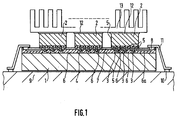
- the module comprises a silicon circuit board 1, three IC chips 2 mounted on a surface of the circuit board 1 according to face-down scheme and a heat dissipation fin 13 mounted on rear surfaces of the IC chips 2 through thermal grease 12.
- Connecting pads 8 are formed on a peripheral portion of the circuit board 1 for electrical connection through lead wires 11 for TAB (Tape Automated Bonding) to connecting pads 10 on a PCB 9 on which the module is to be mounted.
- the IC chip 2 is a complete microprocessor chip obtained through predetermined steps including such as diffusion.
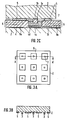
- an organic insulating film 5 having a first thickness is formed and patterned by selective etching with a photo-resist film to form through-holes at desired positions.
- a metal layer 3b of titanium (Ti) or chromium (Cr), etc. is formed to a thickness of 0.1 to 0.3 ⁇ m by vapor deposition and further a metal layer 3a of gold (Au) or copper (Cu), etc., is formed thereon.
- the film 5 is formed by spin-coating the IC chip surface with liquid polyimide and thermosetting it by heating it to a temperature of 400°C to 450°C.
- the thickness of the film 5, that is, the first thickness is selected as 5 ⁇ m
- the structure of the IC chip 2 is shown in plan view in Fig. 3A and in cross section taken along a line A-A in Fig. 3A in Fig. 3B. That is, air releaf paths are provided in the film 5.
- an inorganic insulating film 14 of silicon dioxide (SiO2) or a mixture of silicon dioxide and silicon nitride (SiN) is formed to a thickness of 0.5 ⁇ m to 2.0 ⁇ m through oxidation step or vapor deposition step and, on the film 14, a suitably patterned substrate wiring layer 15 of copper (Cu), gold (Au) or aluminum (Al) is formed.
- the organic insulating film 6 is formed by laminating wiring layers of copper (Cu), gold (Au) or aluminum (Al) with using polyimide layers each having thickness of 15 to 29 ⁇ m and formed by spin coating as in the case of the film 5 on the chip 2 as interlayer insulating films and heating the alternating lamination of the wiring layers and the polyimide layers to thermoset polyimide.
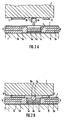
- a square through-hole having each side of 30 to 100 ⁇ m is formed in the insulating film 6 at a predetermined position, that is, a position corresponding to the metal bump 3 of the IC chip by using a similar step to that used in forming the through-hole of the film 5 and filled with solder metal 4.
- the solder metal 4 includes a thin base layer 4c of nickel (Ni) formed on the substrate wiring layer 15 by direct plating, a high melting point metal layer 4b of relatively high melting point metal such as gold-silicon (Au-Si) alloy or lead-tin alloy (95%Pb/5%Sn) formed on the base layer 4c and a low melting point metal layer 4a of indium (In) or eutectic solder, etc., formed on the layer 4b.
- Ni nickel
- Au-Si gold-silicon
- lead-tin alloy 95%Pb/5%Sn
- the certain IC chip 2 may be replaced with a new chip.
- the semi-assembly is further heated to a temperature above the melting point of the solder metal layer 4b while keeping the press contact of the IC chips 2 with the silicon circuit board 1 to thermoset the adhesive resin 7 of the thin polyimide layers and to make the electric connection between the solder metal 4 and the metal bump 3 complete (at this time, the solder metal layers 4a and 4b are melted together to form a single solder metal layer 4d).
- these through-holes have discontinuous walls (not shown) at least in the vicinity of each of them in a circular or square peripheral direction around an axis of the metal bump 3.
- a heat radiator block which may be of stainless steel, has cooling channels through which cooling water flows and exhibits superior cooling effect, to the IC chips through thermal grease.
- a distance between the IC chips and the silicon circuit board is defined by thicknesses of the organic insulating films formed on the IC chip side and the circuit board side, respectively to obtain a uniformity of the gap therebetween. That is, since the height of the metal bump is selected as being smaller than a sum of the thicknesses of these films and the through-holes of these films have discontinuous walls (not shown) at least in the vicinity of each of them in a circular or square peripheral direction around an axis of the metal bump, the space around the metal bump never be sealed.
- the organic insulating film on the side of the circuit board is made thicker to give a large space for melted solder in the through-hole thereof, it is possible to fill the space around the metal bump with a sufficient amount of melted solder when it is dipped therein. Thus, the formation of closed space in the organic insulating film due to melting of solder for connection of the metal bump is avoided. Further, it is possible to form the solder as a double layer structure of a relatively low melting point metal and a high melting point metal and perform electric connection test during the pre-heating step for melting the low melting point metal.
Landscapes
- Wire Bonding (AREA)
Applications Claiming Priority (2)
| Application Number | Priority Date | Filing Date | Title |
|---|---|---|---|
| JP23041890 | 1990-08-31 | ||
| JP230418/90 | 1990-08-31 |
Publications (3)
| Publication Number | Publication Date |
|---|---|
| EP0475223A2 true EP0475223A2 (de) | 1992-03-18 |
| EP0475223A3 EP0475223A3 (en) | 1993-01-27 |
| EP0475223B1 EP0475223B1 (de) | 1997-10-22 |
Family
ID=16907579
Family Applications (1)
| Application Number | Title | Priority Date | Filing Date |
|---|---|---|---|
| EP91114675A Expired - Lifetime EP0475223B1 (de) | 1990-08-31 | 1991-08-30 | Herstellungsverfahren für integrierte Schaltungschip Packung |
Country Status (2)
| Country | Link |
|---|---|
| EP (1) | EP0475223B1 (de) |
| DE (1) | DE69128014T2 (de) |
Cited By (6)
| Publication number | Priority date | Publication date | Assignee | Title |
|---|---|---|---|---|
| EP0581152A3 (de) * | 1992-07-30 | 1994-03-16 | Daimler Benz Ag | |
| EP0638931A3 (de) * | 1993-08-12 | 1995-05-10 | Fujitsu Ltd | Mehrchipmodul. |
| EP1189277A1 (de) * | 2000-09-15 | 2002-03-20 | Alstom | Elektronikschaltungssubstrat und Elektronikmodul damit |
| EP0961319A3 (de) * | 1998-05-28 | 2002-04-24 | Xerox Corporation | Integrierte, flexible Verbindung |
| CN104854965A (zh) * | 2012-12-21 | 2015-08-19 | 埃普科斯股份有限公司 | 器件载体和器件载体装置 |
| CN115050658A (zh) * | 2022-04-25 | 2022-09-13 | 厦门通富微电子有限公司 | 覆晶薄膜的封装方法及覆晶薄膜 |
Families Citing this family (1)
| Publication number | Priority date | Publication date | Assignee | Title |
|---|---|---|---|---|
| JP2014179419A (ja) * | 2013-03-14 | 2014-09-25 | Alpha- Design Kk | 電子部品の接合方法 |
Family Cites Families (2)
| Publication number | Priority date | Publication date | Assignee | Title |
|---|---|---|---|---|
| JPH07112041B2 (ja) * | 1986-12-03 | 1995-11-29 | シャープ株式会社 | 半導体装置の製造方法 |
| JPH01160028A (ja) * | 1987-12-17 | 1989-06-22 | Matsushita Electric Ind Co Ltd | 電極の接続方法 |
-
1991
- 1991-08-30 EP EP91114675A patent/EP0475223B1/de not_active Expired - Lifetime
- 1991-08-30 DE DE69128014T patent/DE69128014T2/de not_active Expired - Fee Related
Cited By (10)
| Publication number | Priority date | Publication date | Assignee | Title |
|---|---|---|---|---|
| EP0581152A3 (de) * | 1992-07-30 | 1994-03-16 | Daimler Benz Ag | |
| EP0638931A3 (de) * | 1993-08-12 | 1995-05-10 | Fujitsu Ltd | Mehrchipmodul. |
| US5586006A (en) * | 1993-08-12 | 1996-12-17 | Fujitsu Limited | Multi-chip module having a multi-layer circuit board with insulating layers and wiring conductors stacked together |
| EP0961319A3 (de) * | 1998-05-28 | 2002-04-24 | Xerox Corporation | Integrierte, flexible Verbindung |
| EP1189277A1 (de) * | 2000-09-15 | 2002-03-20 | Alstom | Elektronikschaltungssubstrat und Elektronikmodul damit |
| FR2814279A1 (fr) * | 2000-09-15 | 2002-03-22 | Alstom | Substrat pour circuit electronique et module electronique utilisant un tel substrat |
| CN104854965A (zh) * | 2012-12-21 | 2015-08-19 | 埃普科斯股份有限公司 | 器件载体和器件载体装置 |
| US10021776B2 (en) | 2012-12-21 | 2018-07-10 | Epcos Ag | Component carrier and component carrier arrangement |
| CN104854965B (zh) * | 2012-12-21 | 2019-01-01 | 埃普科斯股份有限公司 | 器件载体和器件载体装置 |
| CN115050658A (zh) * | 2022-04-25 | 2022-09-13 | 厦门通富微电子有限公司 | 覆晶薄膜的封装方法及覆晶薄膜 |
Also Published As
| Publication number | Publication date |
|---|---|
| EP0475223A3 (en) | 1993-01-27 |
| DE69128014D1 (de) | 1997-11-27 |
| EP0475223B1 (de) | 1997-10-22 |
| DE69128014T2 (de) | 1998-05-20 |
Similar Documents
| Publication | Publication Date | Title |
|---|---|---|
| US5367765A (en) | Method of fabricating integrated circuit chip package | |
| US4862322A (en) | Double electronic device structure having beam leads solderlessly bonded between contact locations on each device and projecting outwardly from therebetween | |
| US6451626B1 (en) | Three-dimensional stacked semiconductor package | |
| EP0704895B1 (de) | Verfahren zur Herstellung einer halbleitenden Anordnung und einer Halbleiterscheibe | |
| US5918364A (en) | Method of forming electrically conductive polymer interconnects on electrical substrates | |
| US6765287B1 (en) | Three-dimensional stacked semiconductor package | |
| US6489687B1 (en) | Semiconductor device and method of manufacturing the same, manufacturing device, circuit board, and electronic equipment | |
| KR100480515B1 (ko) | 반도체 장치 | |
| CN101276809B (zh) | 半导体器件及其制造方法 | |
| US4034468A (en) | Method for making conduction-cooled circuit package | |
| US6822324B2 (en) | Wafer-level package with a cavity and fabricating method thereof | |
| US5357674A (en) | Method of manufacturing a printed circuit board | |
| US6953999B2 (en) | High density chip level package for the packaging of integrated circuits and method to manufacture same | |
| US5506383A (en) | Wafer scale multi-chip module | |
| US20050230797A1 (en) | Chip packaging structure | |
| US6596560B1 (en) | Method of making wafer level packaging and chip structure | |
| US20030197285A1 (en) | High density substrate for the packaging of integrated circuits | |
| US8153516B2 (en) | Method of ball grid array package construction with raised solder ball pads | |
| JPH06342794A (ja) | 樹脂封止型半導体パッケージおよびその製造方法 | |
| US5559316A (en) | Plastic-molded semiconductor device containing a semiconductor pellet mounted on a lead frame | |
| JPH08255965A (ja) | マイクロチップモジュール組立体 | |
| US6458627B1 (en) | Semiconductor chip package and method of fabricating same | |
| JPH07170098A (ja) | 電子部品の実装構造および実装方法 | |
| JP3000975B2 (ja) | 半導体素子の実装構造 | |
| EP0475223B1 (de) | Herstellungsverfahren für integrierte Schaltungschip Packung |
Legal Events
| Date | Code | Title | Description |
|---|---|---|---|
| PUAI | Public reference made under article 153(3) epc to a published international application that has entered the european phase |
Free format text: ORIGINAL CODE: 0009012 |
|
| 17P | Request for examination filed |
Effective date: 19910830 |
|
| AK | Designated contracting states |
Kind code of ref document: A2 Designated state(s): DE FR GB |
|
| RIN1 | Information on inventor provided before grant (corrected) |
Inventor name: KUSAKA, TERUO, C/O NEC CORPORATION |
|
| PUAL | Search report despatched |
Free format text: ORIGINAL CODE: 0009013 |
|
| AK | Designated contracting states |
Kind code of ref document: A3 Designated state(s): DE FR GB |
|
| 16A | New documents despatched to applicant after publication of the search report | ||
| 17Q | First examination report despatched |
Effective date: 19941205 |
|
| GRAG | Despatch of communication of intention to grant |
Free format text: ORIGINAL CODE: EPIDOS AGRA |
|
| GRAH | Despatch of communication of intention to grant a patent |
Free format text: ORIGINAL CODE: EPIDOS IGRA |
|
| GRAH | Despatch of communication of intention to grant a patent |
Free format text: ORIGINAL CODE: EPIDOS IGRA |
|
| GRAA | (expected) grant |
Free format text: ORIGINAL CODE: 0009210 |
|
| AK | Designated contracting states |
Kind code of ref document: B1 Designated state(s): DE FR GB |
|
| REF | Corresponds to: |
Ref document number: 69128014 Country of ref document: DE Date of ref document: 19971127 |
|
| ET | Fr: translation filed | ||
| PLBE | No opposition filed within time limit |
Free format text: ORIGINAL CODE: 0009261 |
|
| STAA | Information on the status of an ep patent application or granted ep patent |
Free format text: STATUS: NO OPPOSITION FILED WITHIN TIME LIMIT |
|
| 26N | No opposition filed | ||
| REG | Reference to a national code |
Ref country code: GB Ref legal event code: IF02 |
|
| REG | Reference to a national code |
Ref country code: GB Ref legal event code: 732E |
|
| PGFP | Annual fee paid to national office [announced via postgrant information from national office to epo] |
Ref country code: FR Payment date: 20030808 Year of fee payment: 13 |
|
| PGFP | Annual fee paid to national office [announced via postgrant information from national office to epo] |
Ref country code: GB Payment date: 20030827 Year of fee payment: 13 |
|
| PGFP | Annual fee paid to national office [announced via postgrant information from national office to epo] |
Ref country code: DE Payment date: 20030911 Year of fee payment: 13 |
|
| REG | Reference to a national code |
Ref country code: FR Ref legal event code: TP |
|
| PG25 | Lapsed in a contracting state [announced via postgrant information from national office to epo] |
Ref country code: GB Free format text: LAPSE BECAUSE OF NON-PAYMENT OF DUE FEES Effective date: 20040830 |
|
| PG25 | Lapsed in a contracting state [announced via postgrant information from national office to epo] |
Ref country code: DE Free format text: LAPSE BECAUSE OF NON-PAYMENT OF DUE FEES Effective date: 20050301 |
|
| GBPC | Gb: european patent ceased through non-payment of renewal fee |
Effective date: 20040830 |
|
| PG25 | Lapsed in a contracting state [announced via postgrant information from national office to epo] |
Ref country code: FR Free format text: LAPSE BECAUSE OF NON-PAYMENT OF DUE FEES Effective date: 20050429 |
|
| REG | Reference to a national code |
Ref country code: FR Ref legal event code: ST |