EP0475258B1 - Selbsttragende Karkasse für Motorfahrzeugreifen - Google Patents
Selbsttragende Karkasse für Motorfahrzeugreifen Download PDFInfo
- Publication number
- EP0475258B1 EP0475258B1 EP19910114893 EP91114893A EP0475258B1 EP 0475258 B1 EP0475258 B1 EP 0475258B1 EP 19910114893 EP19910114893 EP 19910114893 EP 91114893 A EP91114893 A EP 91114893A EP 0475258 B1 EP0475258 B1 EP 0475258B1
- Authority
- EP
- European Patent Office
- Prior art keywords
- tyre
- carcass
- reinforcement
- insert
- inserts
- Prior art date
- Legal status (The legal status is an assumption and is not a legal conclusion. Google has not performed a legal analysis and makes no representation as to the accuracy of the status listed.)
- Expired - Lifetime
Links
- 230000002787 reinforcement Effects 0.000 claims abstract description 41
- 239000011324 bead Substances 0.000 claims description 22
- 239000013536 elastomeric material Substances 0.000 claims description 11
- 239000004753 textile Substances 0.000 claims description 8
- 150000001875 compounds Chemical class 0.000 claims description 7
- 239000005062 Polybutadiene Substances 0.000 claims description 4
- 229920002857 polybutadiene Polymers 0.000 claims description 4
- 239000012188 paraffin wax Substances 0.000 claims description 3
- 230000001747 exhibiting effect Effects 0.000 claims description 2
- 229920005555 halobutyl Polymers 0.000 claims description 2
- 125000004968 halobutyl group Chemical group 0.000 claims description 2
- 238000013459 approach Methods 0.000 claims 1
- 238000005303 weighing Methods 0.000 description 6
- 238000011161 development Methods 0.000 description 5
- 238000012360 testing method Methods 0.000 description 5
- 238000004873 anchoring Methods 0.000 description 4
- 230000006835 compression Effects 0.000 description 4
- 238000007906 compression Methods 0.000 description 4
- 238000009661 fatigue test Methods 0.000 description 4
- 230000006872 improvement Effects 0.000 description 4
- 238000005452 bending Methods 0.000 description 3
- -1 chlorobutyl Chemical group 0.000 description 2
- 230000000694 effects Effects 0.000 description 2
- 238000013021 overheating Methods 0.000 description 2
- 230000009467 reduction Effects 0.000 description 2
- 230000003014 reinforcing effect Effects 0.000 description 2
- 241000531908 Aramides Species 0.000 description 1
- 239000004677 Nylon Substances 0.000 description 1
- 238000005299 abrasion Methods 0.000 description 1
- 230000009471 action Effects 0.000 description 1
- 230000002411 adverse Effects 0.000 description 1
- 230000002547 anomalous effect Effects 0.000 description 1
- 229920003235 aromatic polyamide Polymers 0.000 description 1
- 230000004888 barrier function Effects 0.000 description 1
- 229920005557 bromobutyl Polymers 0.000 description 1
- 229920005556 chlorobutyl Polymers 0.000 description 1
- 230000003750 conditioning effect Effects 0.000 description 1
- 238000010586 diagram Methods 0.000 description 1
- 230000020169 heat generation Effects 0.000 description 1
- 238000003780 insertion Methods 0.000 description 1
- 230000037431 insertion Effects 0.000 description 1
- 238000012423 maintenance Methods 0.000 description 1
- 238000012986 modification Methods 0.000 description 1
- 230000004048 modification Effects 0.000 description 1
- 230000007935 neutral effect Effects 0.000 description 1
- 229920001778 nylon Polymers 0.000 description 1
- 230000000750 progressive effect Effects 0.000 description 1
- 239000007787 solid Substances 0.000 description 1
Images


Classifications
-
- B—PERFORMING OPERATIONS; TRANSPORTING
- B60—VEHICLES IN GENERAL
- B60C—VEHICLE TYRES; TYRE INFLATION; TYRE CHANGING; CONNECTING VALVES TO INFLATABLE ELASTIC BODIES IN GENERAL; DEVICES OR ARRANGEMENTS RELATED TO TYRES
- B60C15/00—Tyre beads, e.g. ply turn-up or overlap
- B60C15/0009—Tyre beads, e.g. ply turn-up or overlap features of the carcass terminal portion
- B60C15/0018—Tyre beads, e.g. ply turn-up or overlap features of the carcass terminal portion not folded around the bead core, e.g. floating or down ply
-
- B—PERFORMING OPERATIONS; TRANSPORTING
- B60—VEHICLES IN GENERAL
- B60C—VEHICLE TYRES; TYRE INFLATION; TYRE CHANGING; CONNECTING VALVES TO INFLATABLE ELASTIC BODIES IN GENERAL; DEVICES OR ARRANGEMENTS RELATED TO TYRES
- B60C13/00—Tyre sidewalls; Protecting, decorating, marking, or the like, thereof
-
- B—PERFORMING OPERATIONS; TRANSPORTING
- B60—VEHICLES IN GENERAL
- B60C—VEHICLE TYRES; TYRE INFLATION; TYRE CHANGING; CONNECTING VALVES TO INFLATABLE ELASTIC BODIES IN GENERAL; DEVICES OR ARRANGEMENTS RELATED TO TYRES
- B60C15/00—Tyre beads, e.g. ply turn-up or overlap
- B60C15/06—Flipper strips, fillers, or chafing strips and reinforcing layers for the construction of the bead
- B60C15/0603—Flipper strips, fillers, or chafing strips and reinforcing layers for the construction of the bead characterised by features of the bead filler or apex
- B60C15/0607—Flipper strips, fillers, or chafing strips and reinforcing layers for the construction of the bead characterised by features of the bead filler or apex comprising several parts, e.g. made of different rubbers
-
- B—PERFORMING OPERATIONS; TRANSPORTING
- B60—VEHICLES IN GENERAL
- B60C—VEHICLE TYRES; TYRE INFLATION; TYRE CHANGING; CONNECTING VALVES TO INFLATABLE ELASTIC BODIES IN GENERAL; DEVICES OR ARRANGEMENTS RELATED TO TYRES
- B60C17/00—Tyres characterised by means enabling restricted operation in damaged or deflated condition; Accessories therefor
- B60C17/0009—Tyres characterised by means enabling restricted operation in damaged or deflated condition; Accessories therefor comprising sidewall rubber inserts, e.g. crescent shaped inserts
-
- B—PERFORMING OPERATIONS; TRANSPORTING
- B60—VEHICLES IN GENERAL
- B60C—VEHICLE TYRES; TYRE INFLATION; TYRE CHANGING; CONNECTING VALVES TO INFLATABLE ELASTIC BODIES IN GENERAL; DEVICES OR ARRANGEMENTS RELATED TO TYRES
- B60C9/00—Reinforcements or ply arrangement of pneumatic tyres
- B60C9/02—Carcasses
- B60C9/14—Carcasses built-up with sheets, webs, or films of homogeneous material, e.g. synthetics, sheet metal, rubber
-
- Y—GENERAL TAGGING OF NEW TECHNOLOGICAL DEVELOPMENTS; GENERAL TAGGING OF CROSS-SECTIONAL TECHNOLOGIES SPANNING OVER SEVERAL SECTIONS OF THE IPC; TECHNICAL SUBJECTS COVERED BY FORMER USPC CROSS-REFERENCE ART COLLECTIONS [XRACs] AND DIGESTS
- Y10—TECHNICAL SUBJECTS COVERED BY FORMER USPC
- Y10T—TECHNICAL SUBJECTS COVERED BY FORMER US CLASSIFICATION
- Y10T152/00—Resilient tires and wheels
- Y10T152/10—Tires, resilient
- Y10T152/10495—Pneumatic tire or inner tube
- Y10T152/10855—Characterized by the carcass, carcass material, or physical arrangement of the carcass materials
- Y10T152/10864—Sidewall stiffening or reinforcing means other than main carcass plies or foldups thereof about beads
Definitions
- the present invention relates to a self-supporting carcass for motor-vehicle tyres, of the type comprising: a pair of circumferentially inextensible anchoring rings or bead cores, each inserted in a bead defined along an inner circumferential edge of a tyre; a pair of elastomeric fillings each of which extends along an outer circumferential edge of one of the anchoring rings and tapers radially away from the tyre axis; one carcass ply and a second carcass ply superposed to the first ply in a radially outer position, at least one of said carcass plies having its edges folded back around the anchoring rings and the elastomeric fillings; a tread band disposed crown-wise to said carcass and a circumferentially inextensible belt structure extending as a ring, interposed between the carcass plies and the tread band and at least a pair of annular reinforcement inserts made of e
- the carcass in accordance with the invention is of the type used when a tyre is wished to be given the capability of covering considerable distances at fair speed even in the case of complete deflation, for example as a result of a puncture.
- the present carcasses for self-supporting tyres having reinforced sidewalls can be substantially classified in two different types.
- One carcass type for example described in US Patent No. 4,193,437, features that at least an annular insert of elastomeric material and lenticular section is inserted in each of the tyre sidewalls, said insert being applied to a position axially internal to the carcass ply or plies.
- This insert has the task of elastically supporting the load weighing on the wheel in case of deflation, due to its resistance to crushing/bending.
- US-A-3 292 681 discloses a tire which is not self-supporting, that is it is not provided for operating in an uninflated condition, and provides for a flexible mid-portion without any insert interposed between the plies; such portion has an extension h comprised between H/4 and H/2 where H is the height of the tire sidewall.
- the main object of the present invention is substantially to solve the problems of the known art, by providing a self-supporting carcass capable of minimising the likelihood that the carcass plies in an axially internal position may work in compression under any use condition, that is when the tyre is properly inflated and when it is deflated, while at the same time moving the plies away from the area in which the maximum heat generation occurs, which will bring about important advantages as regards the thermal level reached and therefore the maintenance of adhesion between the ply cords and the embodying compound.
- Another object of the invention is to provide a carcass imparting optimal flexibility features to the tyre sidewalls for the purpose of achieving excellent comfort under any ride condition.
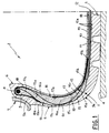
- carcass the structural part constituting the foundation of motor-vehicle tyres usually referred to as carcass, of the self-supporting type in accordance with the present invention, has been generally identified by reference numeral 1.
- the carcass 1 is conventionally associated with a tyre 2.
- a tread band 3 disposed crown-wise to the carcass, shaped as a ring and arranged to act by contact on the road surface (4), as well as two sidewalls 5 extending in a substantially radial manner from the opposite edges of the tread band 3, and two beads 6 defined along the circumferential inner edges of the tyre 2, at which beads the engagement of the tyre by a rim 7 carried by the motor-vehicle on which the tyre is mounted takes place.
- the carcass 1 conventionally provides the presence of a pair of anchoring rings 8, commonly referred to as “bead cores”, each inserted in one of the beads 6.
- the bead cores 8 are circumferentially inextensible and offer the necessary stiffness to the bead 6 so as to enable the proper assembling of the tyre to the rim 7.
- each of the bead cores 8 Extending along the circumferential outer edge of each of the bead cores 8 is an elastomeric filling 9, tapering radially away from the tyre axis.
- a first carcass ply 10 and a second carcass ply 11 overlapping the first ply 10 at a radially external position are provided to extend over the whole section of the tyre 2.
- At least one of the carcass plies 10, 11 has its edges 10a, 11a, folded back around the bead cores 8 and the elastomeric fillings 9.
- Tyre 2 also comprises a belt structure 12 which is circumferentially inextensible and is comprised of one or more radially superposed plies 12a, extending as a ring interposed between the carcass 1 and the tread band 3.
- the thicknesses of the plies 10, 11, 12a are shown in solid blackened lines spaced apart from one another. Actually, the plies are superposed in mutual contact relationship, except in the region of the sidewalls 5, as better clarified in the following.
- the carcass 1 further comprises, for each of the tyre sidewalls 5, a first annular reinforcement insert 13 interposed between the first and second carcass plies 10, 11, and exhibiting an area of maximum thickness 13a disposed substantially in alignment with the circumferential outer edge 9a of the corresponding filling 9. Departing from the area of maximum thickness 13a, is a radially internal portion 13b extending alongside the filling 9 and tapering substantially in alignment with the bead core 8, as well as a radially external portion 13c extending away from the filling 9 and growing thinner as it goes closer to the point of maximum chord in the tyre 2.
- the carcass 1 in accordance with the present invention also comprises a second annular reinforcement insert 15, interposed between the first and second carcass plies 10, 11 as well, at a radially external position relative to the first reinforcement insert 13.
- the second reinforcement insert 15 exhibits an area of maximum thickness 15a disposed at a connecting region, commonly referred to as "buttress" and denoted by 5a, between the sidewall 5 and the tread band 3.
- a radially external portion 15b Departing from the maximum thickness area 15a is a radially external portion 15b extending in a direction substantially parallel to the tyre axis and tapering under a corresponding edge of the belt structure 12, as well as a radially internal portion 15c growing thinner towards the radially external portion 13c of the first annular reinforcement insert 13 and joining the latter at a junction point 14 substantially coincident with said maximum chord point.
- the two reinforcement inserts 13 and 15 must not be necessarily joined together at the junction point 14 neither must they be made of the same elastomeric material; they can be two distinct inserts as regards their elastomeric composition and/or they can be physically separated at the junction point 14 by a third element interposed therebetween, as hereinafter explained.
- a third annular insert 16 of elastomeric material is also provided; it covers the first carcass ply 10 at a position radially internal to the tyre 2.
- the third annular insert 16 exhibits a respective area of maximum thickness 16a substantially disposed in alignment with the junction point 14 between the annular reinforcement inserts 13 and 15. Departing from this area 16a is a radially internal portion 16b tapering substantially in alignment with the area of maximum thickness 13a of the first reinforcement insert 13 and a radially external portion 16c substantially tapering in alignment with the area of maximum thickness 15a of the second reinforcement insert 15.
- the size features of the three inserts 13, 15, 16 can vary depending upon the type of motor-vehicle for which the tyre is designed, as well as the operating features to be given to the tyre itself. On the whole, the thickness of inserts 13, 15, 16 is reduced when the tyre 2 is intended for light-in-weight cars and/or in order to favour the carcass resistance to high speeds with respect to the lifetime under ride conditions with a flat tyre.
- the thickness of the first insert 13 should conveniently be comprised between 2.5 mm and 7 mm, at the area of its maximum thickness 13a, while the thickness of the second insert 15, still referring to its area of maximum thickness 15a, should be in the range of 2.5 mm to 5 mm.
- the thickness of the first and second inserts 13, 15 at the mutual junction area 14 should preferably be less than 3.5 mm.
- the elastomeric material of said inserts conveniently consists of compounds having a high stiffness and a low hysteresis which are known per se and in particular adapted for this type of use.
- a very important function associated with the three inserts 13, 15 and 16 and their sizes, consists in conditioning the development of the ply profile on the right section of the tyre, as better clarified in the following.
- a textile reinforcement strip 17 for example made of nylon or aramide, applied at an axially internal position to the radially external portion 16c of the third insert itself.
- the textile reinforcement strip 17 has a first end edge 17a terminating at a radially internal position relative to the junction point 14, between the first reinforcement insert 13 and the second reinforcement insert 15, as well as a second end edge 17b terminating beyond the end of the radially external portion 16c of the third insert 16.
- the whole inner surface of the carcass 1 can be covered with a layer of halobutyl-based elastomeric material 19 highly impervious to air, consisting for example of chlorobutyl or bromobutyl which, at least in the circumferential area substantially extending astride of the junction point 14 between the first and second reinforcement inserts 13, 15, is replaced by a compound having a high polybutadiene content (at least 30% of parts by weight for 100 parts of compound), to which paraffin is optionally added.
- halobutyl-based elastomeric material 19 highly impervious to air consisting for example of chlorobutyl or bromobutyl which, at least in the circumferential area substantially extending astride of the junction point 14 between the first and second reinforcement inserts 13, 15, is replaced by a compound having a high polybutadiene content (at least 30% of parts by weight for 100 parts of compound), to which paraffin is optionally added.
- the first and second inserts 13, 15 enclosed between the first and second carcass plies 10, 11, substantially behave like two rigid arms mutually hinged at their junction point 14.
- the third insert 16, in turn, substantially behaves like a spring counteracting the tendency of the first and second inserts 13, 15 to move close to each other due to the load weighing on the motor-vehicle wheel.
- the stiffness to crushing of the tyre of the invention is about twice that of the traditional tyres.
- the load weighing on the motor-vehicle wheel is mostly counteracted by the spring reaction supplied by the third insert 16 as a result of its being stressed to compression, said stress being mainly concentrated on the area of maximum thickness 16a.
- the elastomeric material forming the third insert 16 tends to move axially towards the outside of the tyre 2, exerting an important thrust force on the first and second carcass plies 10, 11, at the junction point 14 between the first and second inserts 13, 15. Under this situation, one can be sure that the carcass plies 10, 11, are submitted to tractive stresses on the inner extension of their sectional profile.
- the inner ply or plies by effect of the counter-deflection have tendency to get stretched thereby helping in reducing the likelihood of crushing at the most critical point 14 already supported by the filling 16 and facilitated by the minimization of its distance from the outer ply, that is the ply that mainly controls the local position of the neutral axis under crushing.
- the lunette 15 shapes the inner ply according to the development of the equilibrium profile, while on the contrary the outer ply is deformed locally off-profile with a tendency to discarge most ot the carcass tension onto the inner ply by free inflation.
- the fatigue test consisted in making the tyres under examination run under a completely deflated condition and charged with the exercise load, against a wheel acting as road, at a constant speed and with a controlled drift thrust; as regards the control tyres, one type of tyre in accordance with the known art had a carcass provided with two plies between which, at each of the sidewalls, a single elastomeric insert of lenticular section was interposed.
- a second type of known tyre submitted to test was provided with a carcass having two elastomeric inserts of lenticular section in the sidewalls, one of them interposed between the carcass plies, whereas the other was applied to the inner carcass ply.
- the tyres made in accordance with the invention have substantially shown the same duration (distance covered) as that of the first type of known tyre.
- the duration of the second type of known tyre has been equal to about one third of the duration of the tyre in accordance with the invention.
- Fatigue tests have been then carried out on the same types of tyres with a 70% overload with respect to the rated load and to a normal inflation pressure.
- the tyre of the invention has exhibited a lifetime more than 20% longer than the second type of known tyre.
- the duration of the first type of known tyre has been less than one third as compared with that of the tyre of the present invention.
- Shown in the graph of Fig. 3 are the variations in temperature and crushing depending upon the Telec distance covered, which have been detected by submitting two different embodiments of the tyre in accordance with the invention to the above mentioned fatigue test under deflated conditions, at a constant speed of 60 km/hour. These embodiments are different from each other only due to the presence of the textile reinforcement strips 17 in the sidewalls 5.
- the curves identified by ⁇ ' and T' respectively represent the development of the radial crushings and temperatures exhibited by the tyre having a carcass provided with the textile reinforcement strip 17, depending upon the distance covered.
- the curves identified by ⁇ '' and T'' represent the development of the crushings and temperatures in a tyre devoid of the textile reinforcement strip 17.
- the tyre provided with the reinforcement strips 17 has shown a lower increase in temperature as well as a lower crushing, which is an evidence of a more reduced fatigue of the carcass.
- the embodiment having the reinforcement strip 17 tends to keep the reached asymptotic temperature and crushing conditions, whereas the embodiment devoid of the strip 17, after about 100 kilometers, shows a tendency to a progressive increase in the parametric decay value. Therefore the duration until breakage of the tyre provided with the textile reinforcement strips 17 has been 50% higher than the embodiment in which said strips are not present.
- the present invention attains the intended purposes.
- the carcass in question offers an important improvement in the distribution of stresses in the tyre structure, which brings about a great reduction in the loss of energy due to heat, and therefore a sharp improvement in the tyre lifetime as compared with the tyres of the known art, both with reference to the ride in a condition of normal inflation pressure, and with reference to the ride with a flat tyre.
- the carcass structure in accordance with the invention while giving the tyre the self-support feature, does not prevent the side deformability of the same, which is indispensable to the ends of comfort during the ride.
Landscapes
- Engineering & Computer Science (AREA)
- Mechanical Engineering (AREA)
- Tires In General (AREA)
Claims (10)
- Kraftfahrzeugreifen, der eine selbsttragende Karkasse mit einem Paar von Wulsten (6) und mit einem Paar von Seitenwänden (5), die sich davon radial nach außen erstrecken, und mit einem Umfangsscheitelabschnitt hat, der mit den beiden Seitenwänden verbunden ist, wobei ein Laufflächenband (3) scheitelseitig an der Karkasse angeordnet ist und der Reifen- ein Paar von in Umfangsrichtung nicht dehnbaren Wulstkernen (8), von denen jeder in einem der Wulste (6) eingebettet ist,- ein Paar von elastomeren Füllstoffelementen (9), von denen sich jedes längs eines radial äußeren Randes eines der Wulstkerne (8) erstreckt und sich in eine Richtung radial von der Reifenachse weg verjüngt,- erste (10) und zweite (11) Karkassenlagen, von denen wenigstens eine mit ihren Rändern um die Wulstkerne (8) und die elastomeren Füllstoffelemente (9) umgefaltet ist,- einen in Umfangsrichtung nicht dehnbaren Gurtaufbau (12), der zwischen den Karkassenlagen (10, 11) und dem Laufflächenband (3) angeordnet ist,- ein Paar von inneren Ringeinsätzen (16) aus elastomerem Material, welche die erste und zweite (10, 11) Karkassenlage innen auskleiden und sich im wesentlichen von dem Wulstkern (8) zu einer Stelle unter dem Gurtaufbau (12) erstrecken, sowie- Verstärkungseinsätze aufweist, die aus elastomerem Material hergestellt sind, im Querschnitt insgesamt Linsenform haben und zwischen den beiden Karkassenlagen (10, 11) angeordnet sind,dadurch gekennzeichnet,- daß in jeder Seitenwand (5) ein erster (13) und ein zweiter (15) Verstärkungseinsatz vorgesehen ist, wobei die Verstärkungseinsätze aus elastomerem Material hergestellt sind, im Querschnitt insgesamt Linsenform haben, zwischen den beiden Karkassenlagen (10, 11) angeordnet und miteinander an einer Stelle in der Nähe der Stelle (14) der maximalen Breite des Reifens verbunden sind,- wobei der erste (13) Verstärkungseinsatz einen Bereich maximaler Dicke (13a) hat, der im wesentlichen in fluchtender Ausrichtung zu dem äußeren Umfangsrand (9a) des entsprechenden Füllstoffelements (9) angeordnet ist, und die Einsätze einen Abschnitt (13b), der sich radial nach innen längs des Füllstoffelements (9) erstreckt und sich zu einem dünneren Ende im wesentlichen in fluchtender Ausrichtung zu dem Wulstkern (8) verjüngt, und einen weiteren Abschnitt (13c) haben, der sich radial nach außen von dem Bereich maximaler Dicke (13a) weg erstreckt und dünner wird, wenn er sich der Stelle (14) maximaler Breite des Reifens annähert, und- wobei der zweite Verstärkungseinsatz (15) einen Bereich maximaler Dicke (15a) hat, der im wesentlichen an der Verbindung zwischen der Reifenseitenwand (5) und dem Laufflächenband (3) angeordnet ist, und einen Abschnitt (15b), der sich im wesentlichen parallel zu der Reifenachse erstreckt und sich unter dem Rand des Gurtaufbaus (12) verjüngt, und einen weiteren Abschnitt (15c) hat, der zu dem weiteren Abschnitt (13c) des ersten Verstärkungseinsatzes (13) hin dünner wird, so daß die beiden Karkassenlagen (10, 11) voneinander ausgehend von einem Punkt unter dem Gurtaufbau (12) zu dem Faltpunkt der Lagen (10, 11) um die Wulstkerne (8) und die elastomeren Füllstoffelemente (9) hin, welche diese letzteren umgeben, im wesentlichen getrennt sind.
- Reifen nach Anspruch 1, dadurch gekennzeichnet, daß er für jede Seitenwand (5) weiterhin wenigstens einen Textilverstärkungsstreifen (17) aufweist, der an einer axial inneren Position an dem Ringeinsatz (16) angebracht ist und einen ersten Endrand (17a), der an einer radial inneren Position bezüglich der Verbindungsstelle (14) zwischen dem ersten und zweiten Verstärkungseinsatz (13, 15) endet, und einen zweiten Endrand (17b) bildet, der jenseits des Endes des radial äußeren Abschnitts (16c) des Ringeinsatzes (16) endet.
- Reifen nach Anspruch 1, dadurch gekennzeichnet, daß die Einsätze (13, 15, 16) der axial inneren Karkassenlage (10) an ihrem rechten Abschnitt eine Gleichgewichtsgestalt geben.
- Reifen nach Anspruch 1, dadurch gekennzeichnet, daß er innen mit einer Schicht aus einem elastomeren Material (19) auf Halobutylbasis ausgekleidet ist, das wenigstens an dem Umfangsbereich rittlings zu der Verbindungsstelle (14) zwischen dem ersten und zweiten Verstärkungseinsatz (13, 15) durch eine Mischung ersetzt ist, die einen hohen Polybutadiengehalt hat.
- Reifen nach Anspruch 4, dadurch gekennzeichnet, daß der Polybutadiengehalt nicht weniger als 30 % Gewichtsteile für 100 Mischungsteile beträgt.
- Reifen nach Anspruch 4, dadurch gekennzeichnet, daß die Mischung, die einen hohen Polybutadiengehalt hat, Paraffin enthält.
- Reifen nach Anspruch 1, dadurch gekennzeichnet, daß die Dicke des ersten Verstärkungseinsatzes (13) im Bereich der maximalen Dicke (13a) zwischen 2,5 mm und 7 mm liegt.
- Reifen nach Anspruch 1, dadurch gekennzeichnet, daß die Dicke des zweiten Verstärkungseinsatzes (15) im Bereich der maximalen Dicke (15a) in dem Bereich von 2,5 mm bis 5 mm liegt.
- Reifen nach Anspruch 1, dadurch gekennzeichnet, daß die Dicke des ersten und zweiten Verstärkungseinsatzes (13, 15) an der gegenseitigen Verbindungsstelle (14) weniger als 3,5 mm beträgt.
- Reifen nach Anspruch 1, dadurch gekennzeichnet, daß die Dicke des Ringeinsatzes (16) im Bereich seiner maximalen Dicke (16a) im Bereich von 5 mm bis 15 mm liegt.
Applications Claiming Priority (2)
| Application Number | Priority Date | Filing Date | Title |
|---|---|---|---|
| IT2146690 | 1990-09-14 | ||
| IT2146690A IT1245271B (it) | 1990-09-14 | 1990-09-14 | Carcassa autoportante per pneumatici di autoveicoli |
Publications (2)
| Publication Number | Publication Date |
|---|---|
| EP0475258A1 EP0475258A1 (de) | 1992-03-18 |
| EP0475258B1 true EP0475258B1 (de) | 1995-11-22 |
Family
ID=11182233
Family Applications (1)
| Application Number | Title | Priority Date | Filing Date |
|---|---|---|---|
| EP19910114893 Expired - Lifetime EP0475258B1 (de) | 1990-09-14 | 1991-09-04 | Selbsttragende Karkasse für Motorfahrzeugreifen |
Country Status (7)
| Country | Link |
|---|---|
| US (1) | US5238040A (de) |
| EP (1) | EP0475258B1 (de) |
| JP (1) | JP3109609B2 (de) |
| KR (1) | KR100210480B1 (de) |
| DE (1) | DE69114794T2 (de) |
| ES (1) | ES2082896T3 (de) |
| IT (1) | IT1245271B (de) |
Families Citing this family (50)
| Publication number | Priority date | Publication date | Assignee | Title |
|---|---|---|---|---|
| JPH0459403A (ja) * | 1990-06-28 | 1992-02-26 | Yokohama Rubber Co Ltd:The | ランフラット空気入りラジアルタイヤ |
| DE69211296T2 (de) * | 1991-11-15 | 1997-01-23 | Pirelli | Selbsttragender Luftreifen für Kraftfahrzeugräder mit in die Seitenwände eingearbeiteten elastischen Trageinsätzen |
| US5685927A (en) * | 1992-09-30 | 1997-11-11 | The Goodyear Tire & Rubber Company | Run-flat tire with wet handling design |
| US5263526A (en) * | 1992-09-30 | 1993-11-23 | The Goodyear Tire & Rubber Company | Pneumatic tire having specified bead structure |
| US5368082A (en) * | 1992-09-30 | 1994-11-29 | The Goodyear Tire & Rubber Company | Radial ply pneumatic tire |
| US5427166A (en) * | 1994-01-18 | 1995-06-27 | Michelin Recherche Et Technique S.A. | Run-flat tire with three carcass layers |
| US5725701A (en) * | 1996-03-13 | 1998-03-10 | The Goodyear Tire & Rubber Company | Low pressure all terrain vehicle tire |
| US5879482A (en) * | 1996-03-15 | 1999-03-09 | Goodyear Tire & Rubber Company | Run-flat low-pressure all terrain vehicle (ATV) tire |
| US5795416A (en) * | 1996-08-02 | 1998-08-18 | Michelin Recherche Et Technique | Run-flat tire having partial carcass layers |
| US5871602A (en) * | 1997-05-29 | 1999-02-16 | The Goodyear Tire & Rubber Company | Tire with carcass turn up ends under belt structure |
| US6026878A (en) * | 1997-05-29 | 2000-02-22 | The Goodyear Tire & Rubber Company | Inextensible high temperature resistant tire |
| US5871600A (en) * | 1997-05-29 | 1999-02-16 | The Goodyear Tire & Rubber Company | Runflat tire with different modulus or elongation carcass cords |
| KR100631265B1 (ko) * | 1998-07-10 | 2006-10-02 | 더 굿이어 타이어 앤드 러버 캄파니 | 공압형 레디얼 플라이 런플랫 타이어 |
| BR9903977A (pt) | 1998-09-09 | 2000-10-10 | Goodyear Tire & Rubber | Pneumático de operação plana |
| US6536495B1 (en) | 1998-11-02 | 2003-03-25 | The Goodyear Tire & Rubber Company | Tread stiffening for two ply runflat tire |
| US6166160A (en) * | 1999-02-04 | 2000-12-26 | The Goodyear Tire & Rubber Company | Process for making deodorized rubbery polymer |
| AU4192499A (en) * | 1999-05-18 | 2000-12-05 | Goodyear Tire And Rubber Company, The | Runflat tire construction with ply cords having a variable modulus of elasticity |
| US6695025B1 (en) | 1999-05-18 | 2004-02-24 | The Goodyear Tire & Rubber Company | Runflat tire construction with ply cords having a variable modulus of elasticity |
| WO2000073093A1 (en) * | 1999-05-27 | 2000-12-07 | Michelin Recherche Et Technique | Runflat tire having optimized carcass path |
| US6494242B2 (en) | 1999-05-27 | 2002-12-17 | Michelin Recherche Et Technique | Runflat tire having optimized carcass path |
| US6182728B1 (en) * | 1999-06-04 | 2001-02-06 | Hankook Tire | Pneumatic run flat tire |
| AU4965099A (en) | 1999-07-01 | 2001-01-22 | Goodyear Tire And Rubber Company, The | Fabric support for metal reinforced inner ply of runflat tire |
| US6814120B1 (en) * | 1999-07-01 | 2004-11-09 | The Goodyear Tire & Rubber Company | Fabric support for metal reinforced inner ply of runflat tire |
| US6938657B1 (en) | 1999-08-05 | 2005-09-06 | Pirelli Pneumatici S.P.A. | Tire for a vehicle wheel capable of withstanding the load at low pressure or zero pressure |
| US6843293B1 (en) | 1999-12-16 | 2005-01-18 | The Goodyear Tire & Rubber Company | Variable-stiffness wedge insert for runflat tires |
| JP4516259B2 (ja) * | 1999-12-16 | 2010-08-04 | ザ・グッドイヤー・タイヤ・アンド・ラバー・カンパニー | ランフラットタイヤ用の剛性可変のくさび形インサート |
| DE60112520T2 (de) | 2000-03-31 | 2006-06-08 | Pirelli Pneumatici S.P.A. | Selbsttragender fahrzeugluftreifen und verfahren zur dessen herstellung |
| US6834696B1 (en) | 2000-06-29 | 2004-12-28 | Bridgestone/Firestone North American Tire, Llc | Runflat tire with cantilever-like sidewall construction |
| JP4176473B2 (ja) | 2000-12-22 | 2008-11-05 | ピレリ・タイヤ・ソチエタ・ペル・アツィオーニ | 車両ホイール用自己担持タイヤおよびその製造方法 |
| JP4608108B2 (ja) * | 2001-01-12 | 2011-01-05 | 住友ゴム工業株式会社 | ランフラットタイヤ |
| JP2005503956A (ja) | 2001-09-28 | 2005-02-10 | ピレリ・プネウマティチ・ソチエタ・ペル・アツィオーニ | 車輪用自立タイヤ、およびその製造方法 |
| EP1465947A4 (de) * | 2001-12-13 | 2005-11-30 | Exxonmobil Chem Patents Inc | Thermoplastische vulkanisate für pannenlauffähige reifen |
| DE10221078A1 (de) * | 2002-05-11 | 2003-12-04 | Continental Ag | Pannenlauffähiger Fahrzeugluftreifen |
| US6719029B2 (en) | 2002-08-09 | 2004-04-13 | The Goodyear Tire & Rubber Company | Tire wall gauges to optimize runflat tire ride comfort |
| US20060128907A1 (en) * | 2002-12-12 | 2006-06-15 | Yu Thomas C | Process for making a thermoplastic vulcanizates |
| ATE446855T1 (de) * | 2003-06-24 | 2009-11-15 | Pirelli | Fahrzeugreifen mit cap/base-laufstreifen |
| DE10343599A1 (de) * | 2003-09-20 | 2005-04-28 | Continental Ag | Fahrzeugluftreifen |
| WO2005049340A1 (en) * | 2003-10-31 | 2005-06-02 | Pirelli Pneumatici S.P.A. | High-performance tyre for vehicle wheels |
| US20090065117A1 (en) * | 2004-07-28 | 2009-03-12 | Pirelli Pneumatic S.P.A. | Tyre comprising an epoxidized elastomeric polymer and crosslinkable elastomeric composition |
| US7255146B2 (en) * | 2004-09-13 | 2007-08-14 | Bridgestone Firestone North American Tire, Llc | Apparatus and method of enhancing run-flat travel for pneumatic tires |
| BRPI0520003B1 (pt) * | 2005-04-28 | 2016-02-16 | Pirelli | pneu, composição elastomérica reticulável, e , artigo manufaturado reticulado |
| DE102005041937A1 (de) * | 2005-09-03 | 2007-03-08 | Continental Aktiengesellschaft | Fahrzeugluftreifen und Verfahren zur Herstellung |
| WO2007062671A1 (en) * | 2005-11-29 | 2007-06-07 | Pirelli Tyre S.P.A. | Tire and crosslinkable elastomeric composition |
| JP4757699B2 (ja) * | 2006-04-24 | 2011-08-24 | 株式会社ブリヂストン | 空気入りタイヤの製造方法および空気入りタイヤ |
| US7694708B2 (en) * | 2006-10-10 | 2010-04-13 | The Goodyear Tire & Rubber Company | Tire with sidewall insert |
| FR2925393B1 (fr) * | 2007-12-21 | 2009-12-18 | Michelin Soc Tech | Pneumatique pour roulage a plat pourvu d'une armature supplementaire de flanc. |
| US20100147433A1 (en) * | 2008-12-12 | 2010-06-17 | Thierry Paul-Marie Gabriel Koeune | Self-supporting pneumatic tire |
| US10052919B2 (en) | 2014-04-07 | 2018-08-21 | Bridgestone Americas Tire Operations, Llc | Tire with pre-stressed toroidal element |
| DE102016216732A1 (de) | 2016-09-05 | 2018-03-08 | Continental Reifen Deutschland Gmbh | Fahrzeugluftreifen mit Notlaufeigenschaften |
| JP7035582B2 (ja) * | 2018-02-06 | 2022-03-15 | 住友ゴム工業株式会社 | 二輪車用タイヤ |
Family Cites Families (15)
| Publication number | Priority date | Publication date | Assignee | Title |
|---|---|---|---|---|
| NL130934C (de) * | 1961-04-28 | Michelin & Cie | ||
| FR1355014A (fr) * | 1963-02-01 | 1964-03-13 | Mft Fr Pneumatiques Michelin | Perfectionnements aux enveloppes de pneumatiques |
| LU62689A1 (de) * | 1970-03-01 | 1971-10-13 | ||
| FR2137339B1 (de) * | 1971-05-18 | 1975-03-14 | Michelin & Cie | |
| GB1436725A (en) * | 1972-06-21 | 1976-05-26 | Bridgestone Tire Co Ltd | Pneumatic safety tyre |
| JPS5231404A (en) * | 1975-09-03 | 1977-03-09 | Toyo Tire & Rubber Co Ltd | Safe pneumatic tyre |
| US4193437A (en) * | 1977-09-16 | 1980-03-18 | The B. F. Goodrich Company | Self supporting tire |
| JPS558903A (en) * | 1978-06-29 | 1980-01-22 | Yokohama Rubber Co Ltd:The | Pneumatic tire |
| ZA817371B (en) * | 1980-11-24 | 1982-10-27 | Goodyear Tire & Rubber | A pneumatic safety tire |
| JPS57151402A (en) * | 1981-03-13 | 1982-09-18 | Bridgestone Corp | Pneumatic tyre |
| JPS59106304A (ja) * | 1982-12-09 | 1984-06-20 | Yokohama Rubber Co Ltd:The | 空気入り安全タイヤ |
| JPH06102406B2 (ja) * | 1986-05-28 | 1994-12-14 | 株式会社ブリヂストン | 空気入り安全タイヤ |
| US4790365A (en) * | 1987-09-11 | 1988-12-13 | The Goodyear Tire & Rubber Company | Tire compounds containing syndiotactic-1,2-polybutadiene |
| JP2619702B2 (ja) * | 1988-10-04 | 1997-06-11 | 本田技研工業株式会社 | 対地作業機位置制御装置 |
| IT1228522B (it) * | 1989-03-02 | 1991-06-20 | Pirelli | Pneumatico ad alte prestazioni. |
-
1990
- 1990-09-14 IT IT2146690A patent/IT1245271B/it active IP Right Grant
-
1991
- 1991-08-29 KR KR1019910015016A patent/KR100210480B1/ko not_active Expired - Fee Related
- 1991-09-04 DE DE69114794T patent/DE69114794T2/de not_active Expired - Fee Related
- 1991-09-04 EP EP19910114893 patent/EP0475258B1/de not_active Expired - Lifetime
- 1991-09-04 ES ES91114893T patent/ES2082896T3/es not_active Expired - Lifetime
- 1991-09-16 US US07/760,394 patent/US5238040A/en not_active Expired - Lifetime
- 1991-09-17 JP JP03236512A patent/JP3109609B2/ja not_active Expired - Fee Related
Also Published As
| Publication number | Publication date |
|---|---|
| KR100210480B1 (ko) | 1999-07-15 |
| KR920006147A (ko) | 1992-04-27 |
| JPH04230408A (ja) | 1992-08-19 |
| DE69114794T2 (de) | 1996-07-11 |
| IT9021466A0 (it) | 1990-09-14 |
| ES2082896T3 (es) | 1996-04-01 |
| US5238040A (en) | 1993-08-24 |
| EP0475258A1 (de) | 1992-03-18 |
| DE69114794D1 (de) | 1996-01-04 |
| JP3109609B2 (ja) | 2000-11-20 |
| IT1245271B (it) | 1994-09-13 |
| IT9021466A1 (it) | 1992-03-14 |
Similar Documents
| Publication | Publication Date | Title |
|---|---|---|
| EP0475258A1 (de) | Selbsttragende Karkasse für Motorfahrzeugreifen | |
| JP3261178B2 (ja) | 自動車用の自己支持型タイヤ | |
| US4155392A (en) | Pneumatic tire | |
| US4019551A (en) | Chipperless radial ply tire | |
| JP3501859B2 (ja) | 3枚のカーカス層を有するラン・フラット型タイヤ | |
| KR100293800B1 (ko) | 안전 공기 타이어 | |
| US3954131A (en) | Pneumatic safety tire | |
| JP4221622B2 (ja) | ビード/リム境界部を改良したランフラットタイヤ | |
| US3935892A (en) | Pneumatic tired wheel | |
| EP0314445B1 (de) | Sicherheitsluftreifen | |
| EP0605177B1 (de) | Luftreifen | |
| US4235273A (en) | Pneumatic tires | |
| GB1602754A (en) | Pneumatic safety tyre | |
| CS251051B2 (en) | Pneumatic tyre for motor vehicle's wheel | |
| GB2053815A (en) | Pneumatic safety tire | |
| JP3487910B2 (ja) | タイヤのトレッド支持装置 | |
| US4271889A (en) | Tire with asymmetric radial carcass employing blocks to limit carcass swing and carcass expansion | |
| EP1094956B1 (de) | Notlaufreifen mit gewebeunterlage zur verbesserung der umfangs-und meridionalsteifigkeit und verfahren zur herstellung | |
| EP1242256B1 (de) | Keilschneideinsätze mit variabler steifigkeit für notlaufreifen | |
| EP0984869B1 (de) | Notlaufreifen mit verbessertem plattlaufverhalten | |
| EP4015242B1 (de) | Baugruppe aus luftlosem reifen und felge | |
| EP1097048B1 (de) | Laufflächenverstärkungsmittel für notlaufreifen | |
| US6843293B1 (en) | Variable-stiffness wedge insert for runflat tires | |
| US6561245B1 (en) | Thread reinforcement means for extended mobility tire | |
| US6338374B1 (en) | Runflat tire with fabric underlay and tread insert |
Legal Events
| Date | Code | Title | Description |
|---|---|---|---|
| PUAI | Public reference made under article 153(3) epc to a published international application that has entered the european phase |
Free format text: ORIGINAL CODE: 0009012 |
|
| AK | Designated contracting states |
Kind code of ref document: A1 Designated state(s): DE ES FR GB SE |
|
| 17P | Request for examination filed |
Effective date: 19920919 |
|
| RAP1 | Party data changed (applicant data changed or rights of an application transferred) |
Owner name: PIRELLI COORDINAMENTO PNEUMATICI S.P.A. |
|
| 17Q | First examination report despatched |
Effective date: 19940727 |
|
| GRAA | (expected) grant |
Free format text: ORIGINAL CODE: 0009210 |
|
| AK | Designated contracting states |
Kind code of ref document: B1 Designated state(s): DE ES FR GB SE |
|
| REF | Corresponds to: |
Ref document number: 69114794 Country of ref document: DE Date of ref document: 19960104 |
|
| ET | Fr: translation filed | ||
| REG | Reference to a national code |
Ref country code: ES Ref legal event code: FG2A Ref document number: 2082896 Country of ref document: ES Kind code of ref document: T3 |
|
| PLBE | No opposition filed within time limit |
Free format text: ORIGINAL CODE: 0009261 |
|
| STAA | Information on the status of an ep patent application or granted ep patent |
Free format text: STATUS: NO OPPOSITION FILED WITHIN TIME LIMIT |
|
| 26N | No opposition filed | ||
| REG | Reference to a national code |
Ref country code: GB Ref legal event code: IF02 |
|
| PGFP | Annual fee paid to national office [announced via postgrant information from national office to epo] |
Ref country code: ES Payment date: 20080926 Year of fee payment: 18 |
|
| PGFP | Annual fee paid to national office [announced via postgrant information from national office to epo] |
Ref country code: FR Payment date: 20080917 Year of fee payment: 18 |
|
| PGFP | Annual fee paid to national office [announced via postgrant information from national office to epo] |
Ref country code: GB Payment date: 20080929 Year of fee payment: 18 |
|
| PGFP | Annual fee paid to national office [announced via postgrant information from national office to epo] |
Ref country code: DE Payment date: 20081031 Year of fee payment: 18 |
|
| PGFP | Annual fee paid to national office [announced via postgrant information from national office to epo] |
Ref country code: SE Payment date: 20080929 Year of fee payment: 18 |
|
| EUG | Se: european patent has lapsed | ||
| GBPC | Gb: european patent ceased through non-payment of renewal fee |
Effective date: 20090904 |
|
| REG | Reference to a national code |
Ref country code: FR Ref legal event code: ST Effective date: 20100531 |
|
| PG25 | Lapsed in a contracting state [announced via postgrant information from national office to epo] |
Ref country code: FR Free format text: LAPSE BECAUSE OF NON-PAYMENT OF DUE FEES Effective date: 20090930 Ref country code: DE Free format text: LAPSE BECAUSE OF NON-PAYMENT OF DUE FEES Effective date: 20100401 |
|
| PG25 | Lapsed in a contracting state [announced via postgrant information from national office to epo] |
Ref country code: GB Free format text: LAPSE BECAUSE OF NON-PAYMENT OF DUE FEES Effective date: 20090904 |
|
| PG25 | Lapsed in a contracting state [announced via postgrant information from national office to epo] |
Ref country code: SE Free format text: LAPSE BECAUSE OF NON-PAYMENT OF DUE FEES Effective date: 20090905 |
|
| REG | Reference to a national code |
Ref country code: ES Ref legal event code: FD2A Effective date: 20110708 |
|
| PG25 | Lapsed in a contracting state [announced via postgrant information from national office to epo] |
Ref country code: ES Free format text: LAPSE BECAUSE OF NON-PAYMENT OF DUE FEES Effective date: 20110628 |
|
| PG25 | Lapsed in a contracting state [announced via postgrant information from national office to epo] |
Ref country code: ES Free format text: LAPSE BECAUSE OF NON-PAYMENT OF DUE FEES Effective date: 20090905 |