EP0475333A2 - Automatische Vorrichtung zum Transportieren und Wenden einer Vorlage - Google Patents
Automatische Vorrichtung zum Transportieren und Wenden einer Vorlage Download PDFInfo
- Publication number
- EP0475333A2 EP0475333A2 EP91115223A EP91115223A EP0475333A2 EP 0475333 A2 EP0475333 A2 EP 0475333A2 EP 91115223 A EP91115223 A EP 91115223A EP 91115223 A EP91115223 A EP 91115223A EP 0475333 A2 EP0475333 A2 EP 0475333A2
- Authority
- EP
- European Patent Office
- Prior art keywords
- conveyor
- outer cover
- automatic original
- reversion
- brackets
- Prior art date
- Legal status (The legal status is an assumption and is not a legal conclusion. Google has not performed a legal analysis and makes no representation as to the accuracy of the status listed.)
- Granted
Links
Images


Classifications
-
- G—PHYSICS
- G03—PHOTOGRAPHY; CINEMATOGRAPHY; ANALOGOUS TECHNIQUES USING WAVES OTHER THAN OPTICAL WAVES; ELECTROGRAPHY; HOLOGRAPHY
- G03G—ELECTROGRAPHY; ELECTROPHOTOGRAPHY; MAGNETOGRAPHY
- G03G15/00—Apparatus for electrographic processes using a charge pattern
- G03G15/60—Apparatus which relate to the handling of originals
- G03G15/602—Apparatus which relate to the handling of originals for transporting
-
- G—PHYSICS
- G03—PHOTOGRAPHY; CINEMATOGRAPHY; ANALOGOUS TECHNIQUES USING WAVES OTHER THAN OPTICAL WAVES; ELECTROGRAPHY; HOLOGRAPHY
- G03G—ELECTROGRAPHY; ELECTROPHOTOGRAPHY; MAGNETOGRAPHY
- G03G15/00—Apparatus for electrographic processes using a charge pattern
- G03G15/60—Apparatus which relate to the handling of originals
-
- G—PHYSICS
- G03—PHOTOGRAPHY; CINEMATOGRAPHY; ANALOGOUS TECHNIQUES USING WAVES OTHER THAN OPTICAL WAVES; ELECTROGRAPHY; HOLOGRAPHY
- G03G—ELECTROGRAPHY; ELECTROPHOTOGRAPHY; MAGNETOGRAPHY
- G03G2215/00—Apparatus for electrophotographic processes
- G03G2215/00172—Apparatus for electrophotographic processes relative to the original handling
- G03G2215/00177—Apparatus for electrophotographic processes relative to the original handling for scanning
- G03G2215/00181—Apparatus for electrophotographic processes relative to the original handling for scanning concerning the original's state of motion
- G03G2215/00185—Apparatus for electrophotographic processes relative to the original handling for scanning concerning the original's state of motion original at rest
Definitions
- the present invention relates to an automatic original reversing conveyor which may be attached to an apparatus such as a copying machine or the like in order to reverse an original.
- an automatic original reversing conveyor has a configuration as shown in Fig. 6 (PRIOR ART) in which a conveyor unit 2 transfers an original document onto a mounting plate 1.
- a reversion unit 7 for reversing the original is provided on the outlet side of the conveyor unit 2.
- a reversing guide roller 8 is positioned at the center of the reversion unit 7. Rollers 14 are disposed in the periphery of and to assist the reversing guide roller 8. Furthermore, a first, second, third and fourth conveyor guide 3, 4, 5', and 6, respectively, are disposed consecutively from the outlet roller 21 side of the conveyor unit 2 to form a reversion path S.
- the third conveyor guide 5' is integrally formed with a cover portion for covering the first, second and fourth conveyor guides 3, 4 and 6.
- the change-over pawl 10 diverts the movement of the original between the reversion and discharge paths.
- a photosensor 12 detects the passage of an original through the reversion path S; likewise, a photosensor 13 detects the discharge of an original from a discharge outlet 11.
- the discharge outlet 11 is for final output of an original document after the process is complete.
- An original document which is positioned on the mount plate 1 is sent to the first conveyor guide 3 by a conveyor belt 22 of the conveyor unit 2.
- the original is then directed by the conveyor guides 4 and 5' as it is forwarded by the action of the reversing guide roller 8 and rollers 14 through the reversion path S.
- the change-over pawl 10 is switched to the upper position to send the original downward.
- the fact that the original has been reversed is detected by the photosensor 12 at the position of the fourth conveyor guide 6.
- the reversed original is then placed once again on the mount plate 1 by the action of the conveyor belt 22.
- such an automatic original reversing conveyor is manufactured such that a paper feed unit for sending-out an original, a conveyor unit for mounting the original onto a mount plate, and a reversion unit for reversing the original are all attached to an apparatus body cover. Therefore, each of these parts has a specific tolerance or separation clearance which must be maintained to ensure an optimum quality process. For example, if these various parts or units are not accurately positioned, the original is inevitably displaced during reversion which results in unacceptable reproductions.
- an object of the present invention is to provide an automatic original reversing conveyor in which an original can be straightened when reversed even if the assembled parts of the apparatus are displaced or misaligned.
- the automatic original reversing conveyor includes a paper feed portion for feeding an original, a conveyor portion for conveying the original sent out from the paper feed portion to a mount plate, and a reversion path for reversing the original sent out from the conveyor.
- the unique advantage of the present invention is that the reversion path has a correction mechanism in which the right and left reversion path lengths of the original document can be adjusted in order to align the document. Therefore, the original can be reversed straight even if it was initially misaligned.
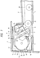
- Fig. 1 is a sectional schematic view of a second embodiment of the automatic original reversing conveyor according to the present invention.
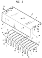
- Fig. 2 is an exploded perspective view showing the outer cover and the third conveyor guide of the second embodiment.
- Fig. 3 is a plan schematic view of the reversion path, the conveyor portion, and the paper feed portion of the second embodiment.
- Fig. 4 is a perspective schematic view to explain the conveyor portion of the second embodiment.
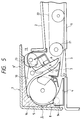
- Fig. 5 is a sectional schematic view showing a first embodiment of the automatic original reversing conveyor according to the present invention.
- Fig. 6 is a sectional schematic view showing a conventional automatic original reversing apparatus.
- the first embodiment of the present invention will be explained with reference to Fig. 5.
- the first embodiment of the present invention includes the same components as the foregoing conventional apparatuses shown in Fig. 6. Therefore, the reference numerals in Fig. 5 correspond to the description of the parts which accompanied Fig. 6.
- an outer cover 9" is attached and covers the four conveyor guides 3, 4, 5, and 6.
- the outer cover 9" is separate from the conveyor guide 5 such that each can move independently.
- the conveyor guide 5 is temporarily mated to the outer cover 9" at a predetermined position. This is accomplished when a pin 15 on the cover 9" is inserted through a hole 53 (Fig. 2).
- a screw 93 is used to temporarily join the brackets 94 and 54 on each side of the ceiling plates 92 and 51. Adjusting the position of the screw 93 in the brackets 94 and 54 alters the reversion path lengths to align an original document.
- Fig. 1 is a sectional schematic view of a conveyor and a reversion unit of the second embodiment of the present invention.
- the conveyor unit 2 transfers an original onto an attached mount plate 1, and a reversion unit 7 reverses the path direction of the original.
- a reversing guide roller 8 is provided at the center of the reversion unit 7; rollers 14 are positioned on the periphery of the reversing guide roller 8 to assist the movement of the original in the reversion path S.
- the reversion path S is further formed by four conveyor guides 3, 4, 5, and 6 which are positioned consecutively from the outlet roller 21.
- An outer cover 9 is attached to cover the conveyor guides 3, 4, 5, and 6.
- the change-over pawl 10 is switched to the upper position to send the original downward. Subsequently, the fact that the original has been reversed is detected by the photosensor 12 at the position of the fourth conveyor guide 6. The reversed original is then positioned once again on the mount plate 1 by the action of the conveyor belt 22. If the change-over pawl 10 were in the down position, the original would be fed toward a discharge outlet 11 and detected by a photo sensor 13.
- the third conveyor guide 5 has a set of ribs 52 extending from the lower surface of its ceiling plate 51 so as to form a curved surface H.
- a hole 53 is formed through the center of the ceiling plate 51.
- the brackets 54 on each end of the ceiling plate 51 have a screw hole 55.
- the outer cover 9 has a rear plate 92 which extends downward from a ceiling plate 91.
- a pin 15 projects downward from the center of the lower surface of the ceiling plate 91.
- the brackets 94 on each end of the ceiling plate 91 have an elongated hole 95.
- the pin 15 is inserted into the hole 53 as shown by a one-dot chained line B.
- the right and left brackets 94 are aligned with the right and left brackets 54, respectively, and a screw 93 is inserted through each of the pairs of holes 95 and 55 as shown by the one-dot chained lines A.
- the parts are designed so that a predetermined gap D exists between the ribs 52 and the rear plate 92 as shown in Fig. 1.
- Fig. 3 is a plan schematic view showing this arrangement. An original document is initially set in the paper feed unit of the automatic original reversion unit 7 to perform first side copying. Consequently, if the original is feed obliquely, balancers 16 on the rear-side end of the reversion unit 7 can be adjusted to thereby align the paper feed unit with the mount plate 1.
- the original For second side copying the original must be reversed by the reversion unit. Therefore, if the original is obliquely displaced or misaligned it can be straightened by adjusting the reversion unit. This adjustment is accomplished by loosening the screws 93 (Fig. 2) and slightly rotating the conveyor guide 5 about the pin 15 relative to the outer cover 9.
- the screws 93 are re-fastened securing the outer cover 9 relative to the conveyor guide 5.
- the left-hand side ribs 52 as shown in Fig. 2 are moved to the downstream side (or the upstream side) and, conversely, the right-hand side ribs 52 are moved to the upstream side (or the downstream side).
- the left (front) and right (rear) reversion path lengths LF and LR of the reversion unit 7 are altered as shown by two-dotted chain lines in Fig. 4 in regard to the direction W of an original.
- the reversion path lengths are those perpendicular to the correct outlet line of the conveyor unit 2.
- the left and right reversion path lengths LF and LR can be altered to be equal or unequal.
- the reversion path lengths should be kept equal if the original is delivered to the reversion unit in an aligned state. In this way the process of reversing the original will not introduce any oblique displacement.
- the reversion path lengths LF an LR can be adjusted to be unequal to correct this misalignment.
- An automatic original reversing conveyor according to the present invention may be designed without a rotating member similar to the conveyor guide 5. In other words, it is sufficient if the right and left path lengths are adjustable.
- the present invention is not limited in this manner either.
- the outer cover 9 may be integrally formed with the conveyor guide 5 so that in adjusting the reversion path lengths LR and LF the outer cover 9 and the conveyor guide 5 move as an integral unit.
- the paper feed portion, the conveyor portion, and the reversion unit are related as individual units in the foregoing description of the present invention, the portions are not always formed separately and may be integrally constructed.
- the reversion unit of the automatic original reversing conveyor according to the present invention has an adjustment mechanism in which the right and left reversion path lengths can be altered. In this way the advantages that for double side copying an original can be reversed in an aligned state and that an original for single side copying remains aligned are clearly realized.
Landscapes
- Physics & Mathematics (AREA)
- General Physics & Mathematics (AREA)
- Registering Or Overturning Sheets (AREA)
- Holders For Sensitive Materials And Originals (AREA)
- Exposure Or Original Feeding In Electrophotography (AREA)
- Conveyance By Endless Belt Conveyors (AREA)
Applications Claiming Priority (2)
| Application Number | Priority Date | Filing Date | Title |
|---|---|---|---|
| JP241735/90 | 1990-09-11 | ||
| JP2241735A JPH0829865B2 (ja) | 1990-09-11 | 1990-09-11 | 自動反転原稿搬送装置 |
Publications (3)
| Publication Number | Publication Date |
|---|---|
| EP0475333A2 true EP0475333A2 (de) | 1992-03-18 |
| EP0475333A3 EP0475333A3 (en) | 1992-08-05 |
| EP0475333B1 EP0475333B1 (de) | 1995-08-09 |
Family
ID=17078761
Family Applications (1)
| Application Number | Title | Priority Date | Filing Date |
|---|---|---|---|
| EP91115223A Expired - Lifetime EP0475333B1 (de) | 1990-09-11 | 1991-09-09 | Automatische Vorrichtung zum Transportieren und Wenden einer Vorlage |
Country Status (4)
| Country | Link |
|---|---|
| US (1) | US5135215A (de) |
| EP (1) | EP0475333B1 (de) |
| JP (1) | JPH0829865B2 (de) |
| DE (1) | DE69111945T2 (de) |
Cited By (1)
| Publication number | Priority date | Publication date | Assignee | Title |
|---|---|---|---|---|
| WO2001079097A1 (en) * | 2000-04-14 | 2001-10-25 | Teknologi & Produkt Udvikling A/S | An apparatus for inverting and returning sheets from a printer for large-sized paper |
Families Citing this family (1)
| Publication number | Priority date | Publication date | Assignee | Title |
|---|---|---|---|---|
| JP5669696B2 (ja) | 2011-08-19 | 2015-02-12 | キヤノン株式会社 | 記録装置および記録媒体の搬送方法 |
Family Cites Families (9)
| Publication number | Priority date | Publication date | Assignee | Title |
|---|---|---|---|---|
| DE2731575C3 (de) * | 1976-09-29 | 1980-04-03 | International Business Machines Corp., Armonk, N.Y. (V.St.A.) | Verfahren und Anordnung zum wahlweisen seitlichen Verschieben von in einer vorgegebenen Richtung zu fördernden Blättern |
| US4262895A (en) * | 1979-08-31 | 1981-04-21 | Xerox Corporation | Inverter with variable buckling control |
| US4487407A (en) * | 1979-10-03 | 1984-12-11 | Xerox Corporation | Trail edge copy registration system |
| JPS582153A (ja) * | 1981-06-22 | 1983-01-07 | Minolta Camera Co Ltd | 排紙装置 |
| US4712786A (en) * | 1985-12-18 | 1987-12-15 | Xerox Corporation | Copy sheet offsetting device |
| US4984779A (en) * | 1987-02-06 | 1991-01-15 | Fuji Xerox Co., Ltd. | Automatic document conveying device for original in a two-sided copy machine |
| JPS63205263A (ja) * | 1987-02-23 | 1988-08-24 | Hitachi Ltd | 熱転写記録装置 |
| JPS63212642A (ja) * | 1987-02-26 | 1988-09-05 | Sharp Corp | 原稿自動搬送装置 |
| JP2763129B2 (ja) * | 1989-03-27 | 1998-06-11 | 株式会社東芝 | 原稿送り装置 |
-
1990
- 1990-09-11 JP JP2241735A patent/JPH0829865B2/ja not_active Expired - Fee Related
-
1991
- 1991-09-09 DE DE69111945T patent/DE69111945T2/de not_active Expired - Fee Related
- 1991-09-09 EP EP91115223A patent/EP0475333B1/de not_active Expired - Lifetime
- 1991-09-11 US US07/757,618 patent/US5135215A/en not_active Expired - Fee Related
Cited By (2)
| Publication number | Priority date | Publication date | Assignee | Title |
|---|---|---|---|---|
| WO2001079097A1 (en) * | 2000-04-14 | 2001-10-25 | Teknologi & Produkt Udvikling A/S | An apparatus for inverting and returning sheets from a printer for large-sized paper |
| US6575455B2 (en) | 2000-04-14 | 2003-06-10 | Teknologi & Produkt Udvikling A/S | Apparatus for inverting and returning sheets from a printer for large-sized paper |
Also Published As
| Publication number | Publication date |
|---|---|
| US5135215A (en) | 1992-08-04 |
| EP0475333A3 (en) | 1992-08-05 |
| EP0475333B1 (de) | 1995-08-09 |
| DE69111945T2 (de) | 1996-02-01 |
| JPH0829865B2 (ja) | 1996-03-27 |
| JPH04121348A (ja) | 1992-04-22 |
| DE69111945D1 (de) | 1995-09-14 |
Similar Documents
| Publication | Publication Date | Title |
|---|---|---|
| US6488275B2 (en) | Active pre-registration system using long sheet transports | |
| JPH0784268B2 (ja) | 給紙装置におけるシートガイド部材の取付構造 | |
| JPS63127927A (ja) | 複写機用の自動原稿供給装置 | |
| US5135215A (en) | Adjustable sheet reverser that compensates for sheet misalignment | |
| US4038921A (en) | Means to connect printing presses in tandem | |
| JP3632145B2 (ja) | 画像読取装置 | |
| US5624111A (en) | Device for aligning sheets at the front lays of a sheet processing machine | |
| JPH02168280A (ja) | 両面印刷プリンタ用レジスト機構及び該機構を備えたプリンタ | |
| US4526364A (en) | Sheet feeding mechanism for duplicating machine with duplexing capability | |
| JPH0439221A (ja) | 画像形成装置の用紙搬送装置 | |
| JPH01104522A (ja) | 給紙機構 | |
| JP2002187643A (ja) | シートの前整合システム | |
| JP2001031279A (ja) | シート供給装置 | |
| US5023669A (en) | Image forming apparatus having an intermediate sheet alignment and receiving unit | |
| KR940001539Y1 (ko) | 복사기의 정착부 용지 이송 조절장치 | |
| JP3462022B2 (ja) | 自動原稿搬送装置 | |
| JPH06138735A (ja) | 自動原稿搬送装置 | |
| JPH0542994Y2 (de) | ||
| US5954329A (en) | Document feeder having an improved separator mechanism | |
| JP3928306B2 (ja) | 用紙搬送装置 | |
| JPH0826555A (ja) | 印刷機adf部の排紙機構 | |
| JPH09185190A (ja) | カウンタバランス機構 | |
| JPS602590Y2 (ja) | 複写原稿自動給送装置 | |
| JP3893803B2 (ja) | 用紙搬送装置 | |
| JPH04106560A (ja) | 転写紙の位置ずれ修正装置 |
Legal Events
| Date | Code | Title | Description |
|---|---|---|---|
| PUAI | Public reference made under article 153(3) epc to a published international application that has entered the european phase |
Free format text: ORIGINAL CODE: 0009012 |
|
| AK | Designated contracting states |
Kind code of ref document: A2 Designated state(s): DE FR GB IT |
|
| PUAL | Search report despatched |
Free format text: ORIGINAL CODE: 0009013 |
|
| AK | Designated contracting states |
Kind code of ref document: A3 Designated state(s): DE FR GB IT |
|
| 17P | Request for examination filed |
Effective date: 19920908 |
|
| 17Q | First examination report despatched |
Effective date: 19940520 |
|
| GRAA | (expected) grant |
Free format text: ORIGINAL CODE: 0009210 |
|
| AK | Designated contracting states |
Kind code of ref document: B1 Designated state(s): DE FR GB IT |
|
| REF | Corresponds to: |
Ref document number: 69111945 Country of ref document: DE Date of ref document: 19950914 |
|
| ITF | It: translation for a ep patent filed | ||
| ET | Fr: translation filed | ||
| PLBE | No opposition filed within time limit |
Free format text: ORIGINAL CODE: 0009261 |
|
| STAA | Information on the status of an ep patent application or granted ep patent |
Free format text: STATUS: NO OPPOSITION FILED WITHIN TIME LIMIT |
|
| 26N | No opposition filed | ||
| PGFP | Annual fee paid to national office [announced via postgrant information from national office to epo] |
Ref country code: GB Payment date: 19970901 Year of fee payment: 7 |
|
| PGFP | Annual fee paid to national office [announced via postgrant information from national office to epo] |
Ref country code: FR Payment date: 19970909 Year of fee payment: 7 |
|
| PGFP | Annual fee paid to national office [announced via postgrant information from national office to epo] |
Ref country code: DE Payment date: 19970912 Year of fee payment: 7 |
|
| PG25 | Lapsed in a contracting state [announced via postgrant information from national office to epo] |
Ref country code: GB Free format text: LAPSE BECAUSE OF NON-PAYMENT OF DUE FEES Effective date: 19980909 |
|
| GBPC | Gb: european patent ceased through non-payment of renewal fee |
Effective date: 19980909 |
|
| PG25 | Lapsed in a contracting state [announced via postgrant information from national office to epo] |
Ref country code: FR Free format text: LAPSE BECAUSE OF NON-PAYMENT OF DUE FEES Effective date: 19990531 |
|
| PG25 | Lapsed in a contracting state [announced via postgrant information from national office to epo] |
Ref country code: DE Free format text: LAPSE BECAUSE OF NON-PAYMENT OF DUE FEES Effective date: 19990701 |
|
| REG | Reference to a national code |
Ref country code: FR Ref legal event code: ST |
|
| PG25 | Lapsed in a contracting state [announced via postgrant information from national office to epo] |
Ref country code: IT Free format text: LAPSE BECAUSE OF NON-PAYMENT OF DUE FEES;WARNING: LAPSES OF ITALIAN PATENTS WITH EFFECTIVE DATE BEFORE 2007 MAY HAVE OCCURRED AT ANY TIME BEFORE 2007. THE CORRECT EFFECTIVE DATE MAY BE DIFFERENT FROM THE ONE RECORDED. Effective date: 20050909 |