EP0475485A1 - Device for positioning textile cops according to the end of their tapered bobbins - Google Patents
Device for positioning textile cops according to the end of their tapered bobbins Download PDFInfo
- Publication number
- EP0475485A1 EP0475485A1 EP91202090A EP91202090A EP0475485A1 EP 0475485 A1 EP0475485 A1 EP 0475485A1 EP 91202090 A EP91202090 A EP 91202090A EP 91202090 A EP91202090 A EP 91202090A EP 0475485 A1 EP0475485 A1 EP 0475485A1
- Authority
- EP
- European Patent Office
- Prior art keywords
- cop
- cams
- supporting
- cops
- flyer
- Prior art date
- Legal status (The legal status is an assumption and is not a legal conclusion. Google has not performed a legal analysis and makes no representation as to the accuracy of the status listed.)
- Withdrawn
Links
- 239000004753 textile Substances 0.000 title claims abstract description 15
- 230000007246 mechanism Effects 0.000 claims abstract description 6
- 239000013013 elastic material Substances 0.000 claims description 6
- 208000027418 Wounds and injury Diseases 0.000 description 4
- 238000009987 spinning Methods 0.000 description 3
- 238000000034 method Methods 0.000 description 2
- 208000034693 Laceration Diseases 0.000 description 1
- 238000009825 accumulation Methods 0.000 description 1
- 230000015572 biosynthetic process Effects 0.000 description 1
- 230000007547 defect Effects 0.000 description 1
- 230000001934 delay Effects 0.000 description 1
- 230000005484 gravity Effects 0.000 description 1
- 238000003780 insertion Methods 0.000 description 1
- 230000037431 insertion Effects 0.000 description 1
- 238000004519 manufacturing process Methods 0.000 description 1
- 238000012986 modification Methods 0.000 description 1
- 230000004048 modification Effects 0.000 description 1
- 238000003825 pressing Methods 0.000 description 1
- 230000000284 resting effect Effects 0.000 description 1
- 238000011144 upstream manufacturing Methods 0.000 description 1
- 238000004804 winding Methods 0.000 description 1
Images


Classifications
-
- B—PERFORMING OPERATIONS; TRANSPORTING
- B65—CONVEYING; PACKING; STORING; HANDLING THIN OR FILAMENTARY MATERIAL
- B65H—HANDLING THIN OR FILAMENTARY MATERIAL, e.g. SHEETS, WEBS, CABLES
- B65H67/00—Replacing or removing cores, receptacles, or completed packages at paying-out, winding, or depositing stations
- B65H67/06—Supplying cores, receptacles, or packages to, or transporting from, winding or depositing stations
- B65H67/061—Orientating devices
-
- B—PERFORMING OPERATIONS; TRANSPORTING
- B65—CONVEYING; PACKING; STORING; HANDLING THIN OR FILAMENTARY MATERIAL
- B65H—HANDLING THIN OR FILAMENTARY MATERIAL, e.g. SHEETS, WEBS, CABLES
- B65H2701/00—Handled material; Storage means
- B65H2701/30—Handled filamentary material
- B65H2701/31—Textiles threads or artificial strands of filaments
Definitions
- the present invention relates to a device for positioning textile cops full of wound thread according to the end of their tapered bobbins onto which the thread is wound.
- the thread produced in ring spinners, or similar machines is collected and wound onto rod-shaped tapered bobbins which have different diameters at each end.
- the accumulation of thread wound onto the bobbins gives rise to the formation of spinning cops, which must be correctly placed and positioned on the automatic loading devices in order to supply the spooling stations.
- Positioning means that the cops must all be placed in the same direction and consequently the direction of taper of their bobbins must all face in the same direction.
- some of the known state-of-the-art devices have positioning and straightening elements which are fixed and not movable.
- the detectors of the position of the cop are slots made in plates, or openings between two fixed elements.
- the said slots or openings are located at the end of a slide, or in a feed channel, or in a feed well or chamber in order to locate the cop to be positioned on them.
- the said slots or openings are calibrated with a smaller width than that of the largest diameter of the cop bobbin and with a larger width than that of the smallest diameter of the cop bobbin. Since the cop bobbins have a slight difference between the diameters of their ends, in such a constructional solution, a slight variation in the width of the two slots, or two openings is evident. Clearly, the slightest deformation of the ends of the cop bobbin, or the laceration of one of the end edges of the said bobbin, creates operational jams in the positioning device during the automatic supply stage of the spooling stations.
- the main aim of the present invention is therefore to ensure correct operation of the entire stage of supplying cops to the spooling stations, so that the faults and disadvantages connected with current state-of-the-art devices, together with those listed above, are avoided.
- An additional aim of the present invention is to provide a device which has a simple constructional structure and is made so that the method of positioning the cops can be carried out quickly and without inconvenience.
- the device covered by the invention in no way alters the operating system and equipment connected with the spooling stations, and so no reference shall be made to the conventional spooling station or to the elements and equipment which enable automatic supply of the cops.
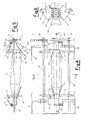
- the present invention relates to a device for positioning textile cops according to the end of their tapered bobbins in which the said device comprises in operational co-ordination:
- the present invention also relates to a device which in practical operation ensures that the distance between the front cams, of both pairs located at either end of the cop, must be such as to be both considerably less than the larger diameter of the tapered bobbin of the cop and also considerably greater than the smaller diameter of the tapered bobbin of the said cop.
- the device for positioning textile cops for the practical embodiment according to the present invention, also provides that one cam of each front pair has a protruding pin on its outer side and the said pin interferes with the flat top extension element of the flyer that is supporting the corresponding end of the cop, which has the larger diameter of its bobbin.
- the device for positioning textile cops for the practical embodiment according to the present invention, also provides that each supporting flyer pivots on a pin round which it rotates overcoming the elastic action of a spiral spring also located around the said pin.
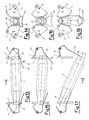
- cop 3 will have the support of flyer 9 withdrawn from its end 24, so that cop 3 rotates falling by gravity around the single support constituted by the other flyer 8.
- the said cop 3 falling downwards will move on vertically into the feed well or channel (not drawn), due solely to its own weight, so that the larger-diameter end 24 will be at the bottom and the smaller-diameter end 22 at the top (see Fig. 17).
- the reverse crosswise thrust of toothed shaft 1 is activated, which re-establishes the initial configuration of the device, waiting to receive and house the next cop to be positioned.
- cop 3 is made upright with its larger-diameter end 24 downwards even if the latter is resting on flyers 8 and 9 with the ends inverted as compared to the position shown in Figures 1 and 13 and described above.
Landscapes
- Spinning Methods And Devices For Manufacturing Artificial Fibers (AREA)
- Spinning Or Twisting Of Yarns (AREA)
Applications Claiming Priority (2)
| Application Number | Priority Date | Filing Date | Title |
|---|---|---|---|
| IT02133090A IT1243708B (it) | 1990-08-29 | 1990-08-29 | Dispositivo per orientare spole tessili secondo l'estremita' dei loro tubetti conici |
| IT2133090 | 1990-08-29 |
Publications (1)
| Publication Number | Publication Date |
|---|---|
| EP0475485A1 true EP0475485A1 (en) | 1992-03-18 |
Family
ID=11180209
Family Applications (1)
| Application Number | Title | Priority Date | Filing Date |
|---|---|---|---|
| EP91202090A Withdrawn EP0475485A1 (en) | 1990-08-29 | 1991-08-15 | Device for positioning textile cops according to the end of their tapered bobbins |
Country Status (2)
| Country | Link |
|---|---|
| EP (1) | EP0475485A1 (it) |
| IT (1) | IT1243708B (it) |
Cited By (2)
| Publication number | Priority date | Publication date | Assignee | Title |
|---|---|---|---|---|
| DE102012014644A1 (de) | 2012-07-24 | 2014-01-30 | Saurer Germany Gmbh & Co. Kg | Vorrichtung zum Wenden von Kopsen und Kopshülsen |
| CN105908294A (zh) * | 2015-02-24 | 2016-08-31 | 村田机械株式会社 | 供纱筒管方向转换装置以及筒管供给系统 |
Citations (5)
| Publication number | Priority date | Publication date | Assignee | Title |
|---|---|---|---|---|
| GB1262015A (en) * | 1968-08-31 | 1972-02-02 | Nuova San Giorgio Spa | Device for orderly arranging cops and spool cores for supply to textile machines |
| FR2367007A1 (fr) * | 1976-10-08 | 1978-05-05 | Maier Metallverarbeitung Gmbh | Dispositif pour dresser dans une orientation correcte des corps de forme elancee, notamment des douilles coniques |
| EP0054775A1 (de) * | 1980-12-23 | 1982-06-30 | Maschinenfabrik Rieter Ag | Vorrichtung zum Sortieren konischer Hülsen |
| EP0276880A2 (en) * | 1987-01-30 | 1988-08-03 | SAVIO S.p.A. | Device for vertically positioning and orienting rod-shaped tubes, in particular conical tubes for textile machines |
| EP0330245A2 (en) * | 1983-05-20 | 1989-08-30 | Maschinenfabrik Rieter Ag | Bobbin inserting device |
-
1990
- 1990-08-29 IT IT02133090A patent/IT1243708B/it active IP Right Grant
-
1991
- 1991-08-15 EP EP91202090A patent/EP0475485A1/en not_active Withdrawn
Patent Citations (5)
| Publication number | Priority date | Publication date | Assignee | Title |
|---|---|---|---|---|
| GB1262015A (en) * | 1968-08-31 | 1972-02-02 | Nuova San Giorgio Spa | Device for orderly arranging cops and spool cores for supply to textile machines |
| FR2367007A1 (fr) * | 1976-10-08 | 1978-05-05 | Maier Metallverarbeitung Gmbh | Dispositif pour dresser dans une orientation correcte des corps de forme elancee, notamment des douilles coniques |
| EP0054775A1 (de) * | 1980-12-23 | 1982-06-30 | Maschinenfabrik Rieter Ag | Vorrichtung zum Sortieren konischer Hülsen |
| EP0330245A2 (en) * | 1983-05-20 | 1989-08-30 | Maschinenfabrik Rieter Ag | Bobbin inserting device |
| EP0276880A2 (en) * | 1987-01-30 | 1988-08-03 | SAVIO S.p.A. | Device for vertically positioning and orienting rod-shaped tubes, in particular conical tubes for textile machines |
Cited By (6)
| Publication number | Priority date | Publication date | Assignee | Title |
|---|---|---|---|---|
| DE102012014644A1 (de) | 2012-07-24 | 2014-01-30 | Saurer Germany Gmbh & Co. Kg | Vorrichtung zum Wenden von Kopsen und Kopshülsen |
| JP2014025191A (ja) * | 2012-07-24 | 2014-02-06 | Oerlikon Textile Gmbh & Co Kg | コップ又は巻管を方向転換する装置 |
| CN105908294A (zh) * | 2015-02-24 | 2016-08-31 | 村田机械株式会社 | 供纱筒管方向转换装置以及筒管供给系统 |
| CN105908294B (zh) * | 2015-02-24 | 2019-11-12 | 村田机械株式会社 | 供纱筒管方向转换装置以及筒管供给系统 |
| DE102016202249B4 (de) | 2015-02-24 | 2024-01-04 | Murata Machinery, Ltd. | Einrichtung zur Veränderung der Richtung einer Garnzuführspule, und Spulen-Zuführsystem |
| DE102016202249B8 (de) | 2015-02-24 | 2024-04-25 | Murata Machinery, Ltd. | Einrichtung zur Veränderung der Richtung einer Garnzuführspule, und Spulen-Zuführsystem |
Also Published As
| Publication number | Publication date |
|---|---|
| IT9021330A1 (it) | 1992-02-29 |
| IT1243708B (it) | 1994-06-21 |
| IT9021330A0 (it) | 1990-08-29 |
Similar Documents
| Publication | Publication Date | Title |
|---|---|---|
| US3946884A (en) | Method for transporting textile yarn packages | |
| US4509703A (en) | Method and apparatus for transporting and storing partially overlapping sheets | |
| JPS6047371B2 (ja) | オ−プンエンド精紡機 | |
| US4015786A (en) | Bobbin changing apparatus | |
| US4480740A (en) | Apparatus for sorting conical bobbin tubes | |
| EP0157654A1 (en) | Method and apparatus for automatically doffing and donning take up packages on a winder | |
| GB1470228A (en) | Yarn package transfer | |
| US3426518A (en) | Thread severing and brushing apparatus | |
| US3532278A (en) | Yarn winding apparatus | |
| GB2200373A (en) | Yarn false twister: donning and doffing truck | |
| US5150845A (en) | Device and method for automatically connecting the yarn to the tube of a winding machine | |
| SU1175360A3 (ru) | Устройство дл одновременной намотки нескольких перемещающихс полос материала в рулон | |
| US3344593A (en) | Doffing machine | |
| US4138070A (en) | Yarn winder | |
| US5029763A (en) | Method and apparatus for transferring packages from winding stations of a textile winding machine | |
| US5431353A (en) | Bobbin winding machine | |
| US4040573A (en) | Method of and apparatus for transporting empty bobbin tubes to a pick-up and delivery station in open-end spinning, winding, yarn texturing and similar machines | |
| EP0112305B1 (en) | Spinning or twisting machine having devices for the simultaneous automatic removal of all cops | |
| US2658325A (en) | Donning mechanism for ring spinning, doubling, and twisting machines | |
| US2921752A (en) | Bobbin tip bunch builder | |
| US4283909A (en) | Spindle cleaning apparatus | |
| US2160810A (en) | Winding machine | |
| US2793490A (en) | Stop motion for textile machines | |
| JPH09111551A (ja) | 繊維機械、特にテクスチャリング機械による糸の加工処理後に、糸を巻いたボビンを取り出す装置 | |
| JPH073543A (ja) | 長繊維及び短繊維用スピンドル台上のボビンを自動的に除去するための装置及び方法 |
Legal Events
| Date | Code | Title | Description |
|---|---|---|---|
| PUAI | Public reference made under article 153(3) epc to a published international application that has entered the european phase |
Free format text: ORIGINAL CODE: 0009012 |
|
| AK | Designated contracting states |
Kind code of ref document: A1 Designated state(s): CH DE FR GB LI |
|
| STAA | Information on the status of an ep patent application or granted ep patent |
Free format text: STATUS: THE APPLICATION IS DEEMED TO BE WITHDRAWN |
|
| 18D | Application deemed to be withdrawn |
Effective date: 19920911 |