EP0475625B1 - Drucker mit einem Bogenschneider - Google Patents
Drucker mit einem Bogenschneider Download PDFInfo
- Publication number
- EP0475625B1 EP0475625B1 EP91307835A EP91307835A EP0475625B1 EP 0475625 B1 EP0475625 B1 EP 0475625B1 EP 91307835 A EP91307835 A EP 91307835A EP 91307835 A EP91307835 A EP 91307835A EP 0475625 B1 EP0475625 B1 EP 0475625B1
- Authority
- EP
- European Patent Office
- Prior art keywords
- printing
- web
- printer
- sheet
- cutter
- Prior art date
- Legal status (The legal status is an assumption and is not a legal conclusion. Google has not performed a legal analysis and makes no representation as to the accuracy of the status listed.)
- Expired - Lifetime
Links
Images



Classifications
-
- B—PERFORMING OPERATIONS; TRANSPORTING
- B41—PRINTING; LINING MACHINES; TYPEWRITERS; STAMPS
- B41J—TYPEWRITERS; SELECTIVE PRINTING MECHANISMS, i.e. MECHANISMS PRINTING OTHERWISE THAN FROM A FORME; CORRECTION OF TYPOGRAPHICAL ERRORS
- B41J11/00—Devices or arrangements of selective printing mechanisms, e.g. ink-jet printers or thermal printers, for supporting or handling copy material in sheet or web form
- B41J11/66—Applications of cutting devices
- B41J11/70—Applications of cutting devices cutting perpendicular to the direction of paper feed
-
- B—PERFORMING OPERATIONS; TRANSPORTING
- B65—CONVEYING; PACKING; STORING; HANDLING THIN OR FILAMENTARY MATERIAL
- B65H—HANDLING THIN OR FILAMENTARY MATERIAL, e.g. SHEETS, WEBS, CABLES
- B65H35/00—Delivering articles from cutting or line-perforating machines; Article or web delivery apparatus incorporating cutting or line-perforating devices, e.g. adhesive tape dispensers
- B65H35/04—Delivering articles from cutting or line-perforating machines; Article or web delivery apparatus incorporating cutting or line-perforating devices, e.g. adhesive tape dispensers from or with transverse cutters or perforators
-
- B—PERFORMING OPERATIONS; TRANSPORTING
- B65—CONVEYING; PACKING; STORING; HANDLING THIN OR FILAMENTARY MATERIAL
- B65H—HANDLING THIN OR FILAMENTARY MATERIAL, e.g. SHEETS, WEBS, CABLES
- B65H43/00—Use of control, checking, or safety devices, e.g. automatic devices comprising an element for sensing a variable
Definitions
- the present invention relates to a printer such as a label printer having a cutter, which can cut a sheet or web at a desired position.
- the printer performs a series of steps including printing the necessary content on each of a plurality of zones (each corresponding to a finished label address form or label such as a postal address form or label form having predetermined form and size) of the sheet material, then cutting the sheet into divisions each constituting a respective one of the labels and adhering the cut divisions automatically onto goods.
- a series of steps of printing-cutting-adhesion is required to be handled rapidly and in large amount.
- EP-A-0 312 201 discloses a printer including a cutter for cutting a sheet into predetermined lengths, each having a printed zone thereon, and means for controlling feeding of the sheet.
- EP-A-0 314 517 discloses apparatus including a paper feeding control device and a cutter for cutting a sheet into predetermined lengths each having a printed zone thereon and including a central processing unit for executing cutting operation of the cutter according to data and programs read out from a storage means.
- An object of the present invention is to provide a printer including a cut control system which can cut the web to a desired size.
- Another object of the present invention is to provide a printer having a cutter which can efficiently perform the operations of printing and cutting, and more particularly shifting the web between the operating positions for printing and cutting.
- a printer including a stepping motor for feeding or advancing a web, a printing head for printing on a surface provided by the web, and a cutter at a distance downstream of the printer head, the cutter being adapted to cut sheets of a predetermined length from the web when the feeding of the web and operation of the printing head are stopped, the sheets corresponding to portions, hereinafter referred to as "sheet divisions", of the web, the printer comprising: storage means for storing one or more printer control programs, said means having a random access memory for storing data comprising a predetermined length of each sheet to be cut from the web, a length of a printing zone in each sheet division and the length of a blank region between the respective printing zones of adjacent sheet divisions; and a central processing unit for controlling operation of the cutter according to the stored data and one or more programs and in accordance with a distance L from a reference position where a predetermined point of one of the sheet divisions is in a predetermined position relative to the printer after printing of each printing zone to
- the storage means stores more than one of said printer control programs; and a second of the printer control programs effects operation of the printer such that after completion of the printing on the printing zone of one sheet division, except the last in respect of which the printer prints on the printing zone, feeding of the web is continued until the web has travelled by the distance L from the reference position, the cutter is then operated, the web is then retracted by the distance L and the feeding of the web is restarted and the printing head starts printing the subsequent sheet division; a third of the printer control programs effects operation of the printer such that after completion of the printing on the printing zone of each sheet division, except the last in respect of which the printer prints on the printing zone, the web is advanced until the web has travelled by the distance L from the reference position, the cutter is operated and the feeding of the web is restarted and the printing head starts printing the subsequent sheet division; and level switching means for selecting any one of the first, second and third programs for effecting operation of the printer.
- Fig. 1 is a block diagram of a printer according to the invention and Fig. 2 is a schematic drawing of the printer.
- the printer comprises a system bus B, a CPU 1, a control program storage means 2, a printing control means 3, a thermal head 4 for printing, a stepping motor 5 for advancing (feeding) and withdrawing a recording web or sheet S (see Fig. 2), a cutter 6 for cutting the sheet at a defined position, a communication interface 7 for transferring information from external sources to the CPU, and input means 23 for an operator.
- the input means 23 may be a keyboard including a level switch 23 a for switching cutting operation levels.
- the control program storage means 2 comprises a rewritable random access memory (RAM) and stores control programs for the printer. Such programs may be a data edition program, a printing control program and also a program for controlling operation of the cutter 6 in relation to printing operation, sheet sending operation (i.e. sheet advance and withdrawal) and other operations.
- the thermal head 4, the stepping motor 5 and the cutter 6 are controlled by the CPU 1 in accordance with the programs stored by the storage means 2.
- the level switch 23 a comprises a part of the keyboard or a manual switch.
- Any one of a number of selection signals may be selectively generated by the switch 23 a or can be input from a host computer through the communication interface 7 with no use of the level switch 23 a .
- a corresponding control program relating to operation of the cutter 6 and feeding and withdrawal of the web is supplied from the storage means 2 to the printing control means 3 in accordance with the signal generated by the switch 23 a .
- the web S is printed on and cut into sheets by the printer.
- the web S may comprise a paper sheet, a plastic film and a tacky (adhesive) paper.
- the printer comprises a web feeding roller 8, an impression roller 9, a platen roll 10 for feeding the web S from the rollers 8 and 9 to the printing head 4, a web driving belt 11, a platen driving belt 12 and belt pulleys 13, 14 15 and 16.
- the cutter 6 is placed downstream of the printing head and may comprise a fixed blade 17, an up-and-down movable blade 18, an eccentric cam 19 for moving the movable blade 18 up and down and a cutter motor 20.
- the movable blade 18 can be of rotary type (rotary blade) in place of up-and-down moving type.
- the web S is cut transversely into sheets of predetermined length each corresponding to a longitudinally extending portion or "sheet division" of the web.
- each of the sheet divisions is to be tacky paper
- the tacky papers are constituted by laminating surface substrate sheets 21 coated with an adhesive onto a release paper web 22 as shown in Fig. 4.
- the width (i.e. the dimension transverse to the feeding direction) and the length (i.e. the dimension extending in the feeding direction) of each surface substrate sheet 21 and the distance between the adjacent surface substrate sheets depend on the type of the tacky papers and the intended use the tacky paper.
- the length of the sheet divisions cut from the web can be varied as required by changing the web travel length L stored in the RAM for each predetermined number of sheet divisions to have a particular length.
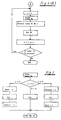
- a program of an operation as a printer (Fig. 3) is started. Any one of three levels (I, II and III) of operation may be selectively executed. The printing operation and the web operation for each level are controlled by the CPU 1 and the printing control means 3.
- the web is advanced and the CPU 1 confirms when the rear edge or other reference point of each sheet division reaches a predetermined reference position l1, which is separated from a travel end position l o in alignment with the blade of the cutter 6 by the web travel length L.
- Fig. 4 illustrates Operation Level I.
- the web S is advanced to a position where printing of the second sheet division is started.
- the printing of the second sheet division proceeds and when the rear edge of the first sheet division has advanced by the web travel length L from the reference position l1 to reach to the position l o in alignment with the blade of the cutter 6, printing is temporarily stopped.
- the first sheet is then cut from the web and the printing of the second sheet division is completed as the web advances.
- Fig. 5 illustrates of Operation Level II.
- the cutter is operated to cut the sheet division from the web.
- the web S is then pulled back or retracted by a distance equal to the length L.
- printing of the second sheet division is started.
- subsequent sheet divisions are printed and cut in the same manner. I.e. the (n + 1)th sheet division is printed and cut in the same manner as the nth sheet division.
- Fig. 6 illustrates Operation Level III.
- the web is advanced by the web travel length L so that the rear edge reaches the position l o and the cutter 6 is operated at this position to cut the sheet division from the web.
- the web is advanced for printing of the second sheet division.
- subsequent sheet divisions are printed and cut in the same manner. I.e. the (n + 1)th sheet division is printed and cut in the same manner as the nth sheet division.
- Operation of the printer can be selected from the three levels mentioned above according to requirements. It is also possible that the level switch 23 a is not provided in the printer but it is constituted to execute only one operation level as a monofunctional device.
- the reference point on the web for determining the start point of the travel distance can be set optionally, for example, at the rear edge of the surface substrate sheet 21. However, the position of the web to be cut can be also determined at the rear end of the printed zone or by the generation of the printing signal itself.
- Operation Level III is same as Level I in that the web does not return by the distance L after the web has been cut and the print quality is good but care should be taken in that the length of blank portions between the printed zones is not increased in the sheet division other than the printed zone.
Landscapes
- Handling Of Sheets (AREA)
Claims (4)
- Drucker, der folgendes umfaßt: einen Schrittmotor (5) zum Vorschieben einer Bahn (S), einen Druckkopf (4) zum Drucken auf einer Oberfläche, die von der Bahn bereitgestellt wird, und eine Trennvorrichtung (6), die dem Druckkopf mit Abstand nachgeschaltet ist, wobei die Trennvorrichtung dafür ausgelegt ist, Bogen einer vorgegebenen Länge von der Bahn abzutrennen, wenn das Vorschieben der Bahn und der Betrieb des Druckkopfes gestoppt werden, wobei die Bogen Teilstücken (Sn) der Bahn entsprechen, die hierin im folgenden als "Bogenabschnitte" bezeichnet werden, wobei der Drucker folgendes umfaßt:
Speichermittel (2) zum Speichern eines oder mehrerer Druckersteuerprogramme, wobei diese Mittel einen Direktzugriffsspeicher zum Speichern von Daten aufweisen, welche eine vorgegebene Länge jedes von der Bahn abzutrennenden Bogens, eine Länge eines Druckbereichs in jedem Bogenabschnitt und die Länge eines Leerbereichs zwischen den jeweiligen Druckbereichen aneinandergrenzender Bogenabschnitte umfassen; und
eine zentrale Rechnereinheit (CPU) zum Steuern des Betriebs der Trennvorrichtung gemäß den gespeicherten Daten und einem oder mehreren Programmen und gemäß einer Entfernung L zwischen einer Bezugsposition, in der sich nach dem Drucken jedes Druckbereichs ein vorgegebener Punkt einer der Bogenabschnitte in einer vorgegebenen Position relativ zum Drucker befindet, und einer Weg-Endposition, in der eine Querlinie der Bahn, die eine Hinterkante des Bogenabschnitts werden soll, mit einer Trennlinie der Trennvorrichtung ausgerichtet ist;
dadurch gekennzeichnet, daß das Druckersteuerprogramm bzw. ein erstes der Druckersteuerprogramme einen Betrieb des Druckers derart bewirkt, daß nach der Beendigung des Druckens auf den Druckbereich jedes Bogenabschnitts, ausgenommen der letzte, bezüglich dessen der Drucker auf den Druckbereich druckt, und wenn die Bahn um eine Entfernung vom Drucker vorgeschoben ist, die gleich der Länge des Leerbereichs ist, das Drucken auf den Druckbereich des nachfolgenden Bogenabschnitts begonnen wird, wenn die Bahn die Entfernung L von der Bezugsposition zurückgelegt hat, das Drucken mittels des Druckkopfes auf den nachfolgenden Bogenabschnitt unterbrochen wird, die Trennvorrichtung betätigt wird und das Vorschieben der Bahn wiederaufgenommen wird, so daß der Druckkopf fortfährt, den nachfolgenden Bogenabschnitt zu bedrucken. - Drucker nach Anspruch 1, bei dem:
die Speichermittel mehr als eines der Druckersteuerprogramme speichern; und
ein zweites der Druckersteuerprogramme einen Betrieb des Druckers derart bewirkt, daß nach Beendigung des Druckens auf den Druckbereich eines Bogenabschnitts, ausgenommen der letzte, bezüglich dessen der Drucker auf den Druckbereich druckt, das Vorschieben der Bahn fortgesetzt wird, bis die Bahn die Entfernung L von der Bezugsposition zurückgelegt hat, dann die Trennvorrichtung betätigt wird, die Bahn dann um die Entfernung L eingezogen wird und das Vorschieben der Bahn wiederaufgenommen wird und der Druckkopf beginnt, den nachfolgenden Bogenabschnitt zu bedrucken;
ein drittes der Druckersteuerprogramme einen Betrieb des Druckers derart bewirkt, daß nach Beendigung des Druckens auf den Druckbereich jedes Bogenabschnitts, ausgenommen der letzte, bezüglich dessen der Drucker auf den Druckbereich druckt, die Bahn vorgeschoben wird, bis die Bahn die Entfernung L von der Bezugsposition zurückgelegt hat, die Trennvorrichtung betätigt wird und das Vorschieben der Bahn wiederaufgenommen wird und der Druckkopf beginnt, den nachfolgenden Bogenabschnitt zu bedrucken; und
Stufenschaltmittel (23a) zum Auswählen eines beliebigen des ersten, zweiten bzw. dritten Programms zum Bewirken eines Betriebs des Druckers. - Drucker nach Anspruch 2, bei dem das Stufenschaltmittel von Hand betätigt werden kann, um ein beliebiges des ersten, zweiten bzw. dritten Programms auszuwählen.
- Drucker nach einem der vorhergehenden Ansprüche, bei dem die Druckersteuerprogramme eines oder mehrere eines Datenedierungsprogramms, eines Drucksteuerprogramms und eines Trennvorrichtungs-Steuerprogramms umfassen.
Applications Claiming Priority (4)
| Application Number | Priority Date | Filing Date | Title |
|---|---|---|---|
| JP230841/90 | 1990-08-31 | ||
| JP23084190 | 1990-08-31 | ||
| JP249861/90 | 1990-09-18 | ||
| JP24986190 | 1990-09-18 |
Publications (3)
| Publication Number | Publication Date |
|---|---|
| EP0475625A2 EP0475625A2 (de) | 1992-03-18 |
| EP0475625A3 EP0475625A3 (en) | 1993-03-31 |
| EP0475625B1 true EP0475625B1 (de) | 1996-05-22 |
Family
ID=26529569
Family Applications (1)
| Application Number | Title | Priority Date | Filing Date |
|---|---|---|---|
| EP91307835A Expired - Lifetime EP0475625B1 (de) | 1990-08-31 | 1991-08-28 | Drucker mit einem Bogenschneider |
Country Status (3)
| Country | Link |
|---|---|
| US (1) | US5188470A (de) |
| EP (1) | EP0475625B1 (de) |
| DE (1) | DE69119673T2 (de) |
Families Citing this family (19)
| Publication number | Priority date | Publication date | Assignee | Title |
|---|---|---|---|---|
| JPH0584994A (ja) * | 1991-09-26 | 1993-04-06 | Brother Ind Ltd | テープ印字装置 |
| JP2556233B2 (ja) * | 1992-01-07 | 1996-11-20 | ブラザー工業株式会社 | テープ印字装置 |
| JP2665155B2 (ja) * | 1994-07-20 | 1997-10-22 | 甲府日本電気株式会社 | 連続用紙切断装置 |
| US5464289A (en) * | 1994-08-24 | 1995-11-07 | Beaudry; Wallace J. | Electrographic label printing system |
| US5452959A (en) * | 1994-08-26 | 1995-09-26 | Ko-Pack Corporation | Apparatus for printing characters onto both surfaces of a sheet material |
| US5524996A (en) * | 1994-11-22 | 1996-06-11 | Grand Rapids Label Company | Linerless label printing apparatus |
| DE69535836D1 (de) * | 1994-11-29 | 2008-10-23 | Seiko Epson Corp | Banddruckvorrichtung |
| US6120200A (en) * | 1994-11-29 | 2000-09-19 | King Jim Co., Ltd. | Tape printing device |
| DE19525713C1 (de) * | 1995-07-15 | 1996-11-14 | Csat Computer Systeme | Vorrichtung zum Bedrucken einer markierungsfreien Endlosfolie |
| US5804023A (en) * | 1996-09-20 | 1998-09-08 | Grand Rapids Label Company | Label cutting and applying apparatus |
| JP3756302B2 (ja) | 1997-10-30 | 2006-03-15 | 三菱電機株式会社 | 画像印画装置 |
| JP3635480B2 (ja) * | 1998-03-31 | 2005-04-06 | カシオ計算機株式会社 | 印字装置 |
| JP4419942B2 (ja) * | 2005-02-14 | 2010-02-24 | セイコーエプソン株式会社 | 印刷後処理支援システムおよび印刷後処理支援プログラム、並びに印刷後処理支援方法 |
| US7486979B2 (en) * | 2005-09-30 | 2009-02-03 | Nellcor Puritan Bennett Llc | Optically aligned pulse oximetry sensor and technique for using the same |
| JP5123707B2 (ja) | 2008-03-28 | 2013-01-23 | 富士通フロンテック株式会社 | プリンタ装置および搭乗券のカット位置制御方法 |
| JP5617466B2 (ja) * | 2010-09-15 | 2014-11-05 | セイコーエプソン株式会社 | 記録装置および記録・カット制御方法 |
| JP2013071313A (ja) * | 2011-09-28 | 2013-04-22 | Casio Computer Co Ltd | 印字装置、印字方法、及び、印字制御プログラム |
| CN105729987A (zh) * | 2016-02-05 | 2016-07-06 | 陈益币 | 一种上下刀卷筒印刷专版定位横切机的跟踪横切方法 |
| JP7177645B2 (ja) * | 2018-09-25 | 2022-11-24 | 東芝テック株式会社 | プリンタおよびプログラム |
Citations (2)
| Publication number | Priority date | Publication date | Assignee | Title |
|---|---|---|---|---|
| EP0312201A1 (de) * | 1987-08-24 | 1989-04-19 | Brother Kogyo Kabushiki Kaisha | Einrichtung und Verfahren zur Kontrolle des Blattvorschubes in einem Drucker |
| EP0314517A2 (de) * | 1987-10-30 | 1989-05-03 | Brother Kogyo Kabushiki Kaisha | Einrichtung zum Steuern der Papierzufuhr in einem Registrierapparat |
Family Cites Families (5)
| Publication number | Priority date | Publication date | Assignee | Title |
|---|---|---|---|---|
| IT1136172B (it) * | 1980-04-09 | 1986-08-27 | Cir Spa Divisione Sasib | Dispositivo a regolazione elettronica per il taglio progressivo in foglietti di una bobina di nastro di materilae in foglio anche stampato |
| JPS61132362A (ja) * | 1984-11-30 | 1986-06-19 | Toshiba Corp | 感熱転写記録方法 |
| JPS63173675A (ja) * | 1987-01-14 | 1988-07-18 | Fujitsu Ltd | 投票券発売機の高速連続印刷方式 |
| US4925325A (en) * | 1987-04-23 | 1990-05-15 | Brother Kogyo Kabushiki Kaisha | Recording paper transporting device in a recording apparatus |
| DE58906707D1 (de) * | 1988-12-02 | 1994-02-24 | Bay Otto | Verfahren und Vorrichtung zum Erstellen, Ausschneiden und Falten von Zeichnungsblättern. |
-
1991
- 1991-08-28 EP EP91307835A patent/EP0475625B1/de not_active Expired - Lifetime
- 1991-08-28 DE DE69119673T patent/DE69119673T2/de not_active Expired - Fee Related
- 1991-08-29 US US07/752,027 patent/US5188470A/en not_active Expired - Fee Related
Patent Citations (2)
| Publication number | Priority date | Publication date | Assignee | Title |
|---|---|---|---|---|
| EP0312201A1 (de) * | 1987-08-24 | 1989-04-19 | Brother Kogyo Kabushiki Kaisha | Einrichtung und Verfahren zur Kontrolle des Blattvorschubes in einem Drucker |
| EP0314517A2 (de) * | 1987-10-30 | 1989-05-03 | Brother Kogyo Kabushiki Kaisha | Einrichtung zum Steuern der Papierzufuhr in einem Registrierapparat |
Also Published As
| Publication number | Publication date |
|---|---|
| US5188470A (en) | 1993-02-23 |
| EP0475625A3 (en) | 1993-03-31 |
| DE69119673D1 (de) | 1996-06-27 |
| DE69119673T2 (de) | 1996-10-31 |
| EP0475625A2 (de) | 1992-03-18 |
Similar Documents
| Publication | Publication Date | Title |
|---|---|---|
| US5188470A (en) | Printer control system for a sheet cutter | |
| EP0711670B1 (de) | Bandschneidegerät | |
| US5232297A (en) | Printing device with margin setting for cut tape | |
| US20090285617A1 (en) | Tape Printing Apparatus and Tape Cassette | |
| EP0580438A2 (de) | Streifendrucker | |
| KR970015030A (ko) | 테이프프린터 | |
| KR19980018823A (ko) | 문자정보 인쇄장치(A printer of a character information) | |
| EP0719650A2 (de) | Verfahren für Farbstrahldrucker auf einem bandförmigen Aufzeichnungsmedium und Aufzeichnungsträger | |
| GB2128139A (en) | Duplex printing system | |
| US5159350A (en) | Tape printing apparatus | |
| JP3713955B2 (ja) | 印刷装置 | |
| JPS5931477B2 (ja) | 印刷装置 | |
| EP1075960B1 (de) | Verfahren zum Buchstabendruck unter Verwendung eines thermischen Liniendruckkopfs | |
| US6517200B1 (en) | Transport buffer having force limiting drive means and method | |
| US20030177880A1 (en) | Cutter system for multi size photographic prints | |
| EP0374567B1 (de) | Elektrostatischer Drucker mit Endlospapier | |
| JPH07112498A (ja) | ラベル加工装置及びラベル印刷装置 | |
| JP2019063997A (ja) | 印刷装置、その印刷装置の印刷方法及びプログラム | |
| JP2005007802A (ja) | ラベルプリンタ | |
| JPH058475A (ja) | プリンタ | |
| US11958286B2 (en) | Printer | |
| JP3295500B2 (ja) | ラベル印字装置 | |
| JP3942994B2 (ja) | 印刷システム | |
| JPH05305738A (ja) | 印字装置 | |
| JPH11254791A (ja) | 用紙仕分け装置、印刷装置及び方法、印刷システム、並びに記録媒体 |
Legal Events
| Date | Code | Title | Description |
|---|---|---|---|
| PUAI | Public reference made under article 153(3) epc to a published international application that has entered the european phase |
Free format text: ORIGINAL CODE: 0009012 |
|
| AK | Designated contracting states |
Kind code of ref document: A2 Designated state(s): DE FR GB |
|
| RIN1 | Information on inventor provided before grant (corrected) |
Inventor name: FUJII, KENICHI Inventor name: HONGO, TAKAYASU Inventor name: SASABE, SETSUO Inventor name: MATSUBARA, MOTOKI |
|
| PUAL | Search report despatched |
Free format text: ORIGINAL CODE: 0009013 |
|
| AK | Designated contracting states |
Kind code of ref document: A3 Designated state(s): DE FR GB |
|
| 17P | Request for examination filed |
Effective date: 19930513 |
|
| RAP1 | Party data changed (applicant data changed or rights of an application transferred) |
Owner name: NEW OJI PAPER CO., LTD. |
|
| 17Q | First examination report despatched |
Effective date: 19940809 |
|
| GRAA | (expected) grant |
Free format text: ORIGINAL CODE: 0009210 |
|
| AK | Designated contracting states |
Kind code of ref document: B1 Designated state(s): DE FR GB |
|
| ET | Fr: translation filed | ||
| REF | Corresponds to: |
Ref document number: 69119673 Country of ref document: DE Date of ref document: 19960627 |
|
| PLBE | No opposition filed within time limit |
Free format text: ORIGINAL CODE: 0009261 |
|
| STAA | Information on the status of an ep patent application or granted ep patent |
Free format text: STATUS: NO OPPOSITION FILED WITHIN TIME LIMIT |
|
| 26N | No opposition filed | ||
| PGFP | Annual fee paid to national office [announced via postgrant information from national office to epo] |
Ref country code: FR Payment date: 19990810 Year of fee payment: 9 |
|
| PGFP | Annual fee paid to national office [announced via postgrant information from national office to epo] |
Ref country code: GB Payment date: 19990825 Year of fee payment: 9 |
|
| PGFP | Annual fee paid to national office [announced via postgrant information from national office to epo] |
Ref country code: DE Payment date: 19990827 Year of fee payment: 9 |
|
| PG25 | Lapsed in a contracting state [announced via postgrant information from national office to epo] |
Ref country code: GB Free format text: LAPSE BECAUSE OF NON-PAYMENT OF DUE FEES Effective date: 20000828 |
|
| GBPC | Gb: european patent ceased through non-payment of renewal fee |
Effective date: 20000828 |
|
| PG25 | Lapsed in a contracting state [announced via postgrant information from national office to epo] |
Ref country code: FR Free format text: LAPSE BECAUSE OF NON-PAYMENT OF DUE FEES Effective date: 20010430 |
|
| PG25 | Lapsed in a contracting state [announced via postgrant information from national office to epo] |
Ref country code: DE Free format text: LAPSE BECAUSE OF NON-PAYMENT OF DUE FEES Effective date: 20010501 |
|
| REG | Reference to a national code |
Ref country code: FR Ref legal event code: ST |