EP0475654B1 - Druckgussform mit Entgasungsanordnung und Ausbauvorrichtung für die Entgasungsanordnung - Google Patents
Druckgussform mit Entgasungsanordnung und Ausbauvorrichtung für die Entgasungsanordnung Download PDFInfo
- Publication number
- EP0475654B1 EP0475654B1 EP19910308033 EP91308033A EP0475654B1 EP 0475654 B1 EP0475654 B1 EP 0475654B1 EP 19910308033 EP19910308033 EP 19910308033 EP 91308033 A EP91308033 A EP 91308033A EP 0475654 B1 EP0475654 B1 EP 0475654B1
- Authority
- EP
- European Patent Office
- Prior art keywords
- unit
- metal mold
- gas venting
- venting unit
- recessed portion
- Prior art date
- Legal status (The legal status is an assumption and is not a legal conclusion. Google has not performed a legal analysis and makes no representation as to the accuracy of the status listed.)
- Expired - Lifetime
Links
- 238000013022 venting Methods 0.000 title claims description 117
- 239000002184 metal Substances 0.000 title claims description 109
- 238000001746 injection moulding Methods 0.000 title claims description 15
- 238000003780 insertion Methods 0.000 claims description 95
- 230000037431 insertion Effects 0.000 claims description 95
- 238000004891 communication Methods 0.000 claims description 7
- 238000005266 casting Methods 0.000 description 10
- 238000001514 detection method Methods 0.000 description 8
- 238000007689 inspection Methods 0.000 description 6
- 238000012423 maintenance Methods 0.000 description 6
- 239000012530 fluid Substances 0.000 description 4
- 238000002347 injection Methods 0.000 description 3
- 239000007924 injection Substances 0.000 description 3
- 230000004044 response Effects 0.000 description 3
- 239000000463 material Substances 0.000 description 2
- 230000007246 mechanism Effects 0.000 description 2
- 230000015572 biosynthetic process Effects 0.000 description 1
- 230000008859 change Effects 0.000 description 1
- 238000010276 construction Methods 0.000 description 1
- 230000000994 depressogenic effect Effects 0.000 description 1
- 238000004512 die casting Methods 0.000 description 1
- 238000004519 manufacturing process Methods 0.000 description 1
- 238000012986 modification Methods 0.000 description 1
- 230000004048 modification Effects 0.000 description 1
- 230000002093 peripheral effect Effects 0.000 description 1
Images



Classifications
-
- B—PERFORMING OPERATIONS; TRANSPORTING
- B22—CASTING; POWDER METALLURGY
- B22D—CASTING OF METALS; CASTING OF OTHER SUBSTANCES BY THE SAME PROCESSES OR DEVICES
- B22D17/00—Pressure die casting or injection die casting, i.e. casting in which the metal is forced into a mould under high pressure
- B22D17/14—Machines with evacuated die cavity
- B22D17/145—Venting means therefor
Definitions
- the present invention relates to a gas venting arrangement in an injection molding apparatus such as a die casting machine according to the preambles of claims 1 and 6. More, particularly, the invention relates to a metal mold structure having a gas venting unit provided separately and detachably from a stationary or movable metal mold of the metal mold structure, and a jig for facilitating a removal of the gas venting unit from the stationary or movable metal mold.
- FIG. 8 One example of a conventional injection molding apparatus is described in: Japanese Patent Application JP-A-63-313645.
- the disclosed apparatus is shown in Fig. 8.
- a stationary metal mold 1 and a movable metal mold 3 are provided, and a mold cavity 9 is formed therebetween.
- the mold cavity 9 has a lower end portion in communication with a runner 5 through a gate 7.
- a casting sleeve 11 is insertedly disposed which is in communication with a lower end of the runner 5.
- the casting sleeve 11 has another end formed with a casting port 13 through which the molten metal is casted.
- a plunger 15 is slidably accommodated which is reciprocable in an axial direction of the casting sleeve 11.
- the plunger 15 is connected to an injection cylinder 19 through a plunger rod 17.
- the plunger 15 is reciprocable within the casting sleeve 11 for urging the molten metal toward the mold cavity 9.
- a striker 21 is provided on the plunger rod 17.
- a limit switch 23 for starting vacuum evacuation and a high speed limit switch 25 are provided at positions along a moving stroke of the striker 21. In accordance with the axial motion of the plunger rod 17, the striker 21 is abuttable against the limit switches 23 and 25.
- a parting faces 27 are defined at confronting surfaces of the stationary and the movable metal molds 1 and 3. and a gas vent passage 29 is formed at an upper portion of the parting face 27.
- the gas vent passage 29 is connected to a vacuum suction means 33 through a pipe 31.
- the vacuum suction means 33 includes an electromagnetic change-over valve 35, a tank 37, a vacuum pump 39 and a drive motor 41.
- the electromagnetic change-over valve 35 has a first change-over position 35a and a second change-over position 35b, and when the valve 35 is changed over to the first change-over position 35a, the gas vent passage 29 is brought to fluid communication with the vacuum suction means 33.
- a gas vent valve 43 is positioned in the gas vent passage 29.
- the gas vent valve 43 is opened or closed by a valve driving mechanism 45. That is, the gas vent valve 43 includes a valve body 47 and a valve stem 49 which is connected to a piston 53 slidably disposed in a valve driving cylinder 51.
- the valve driving mechanism 45 includes a compressor 55 and an electromagnetic change-over valve 57.
- the compressor 55 is connected to the valve driving cylinder 51 through the electromagnetic change-over valve 57 and pipes 59, 61.
- a compressed air from the compressor 55 is applied to one of a front chamber 63 and a rear chamber 65 of the valve driving cylinder 51 through the valve 57 and one of the pipes 59 and 61.
- the piston 53 is slidably moved in the cylinder 51 so as to move the valve body 47 toward and away from a valve seat portion 67 for closing or opening the gas vent valve.
- the electromagnetic valve 57 has a first change-over position 57a and a second change-over position 57b.
- the compressive air is supplied to the front chamber 63 through the pipe 59 for retractingly moving the piston 53 to seat the valve body 47 onto the valve seat 67, to thereby shut off the fluid communication between the gas vent passage 29 and the pipe 31.
- the electromagnetic valve 57 has the second change-over position 57b
- the compressed air is supplied to the rear chamber 65 through the pipe 61 for frontwardly moving the piston 53 to move the valve body 47 away from the valve seat 67, to thereby provide fluid communication between the gas vent passage 29 and the pipe 31.
- a detection rod 69 is disposed at the gas vent passage 29.
- the detection rod 69 detects the molten metal urged upwardly in the gas vent passage for transmitting a molten metal detection signal to an electrical or electronic circuit (not shown).
- the electrical circuit will send control signal to the electromagnetic change-over valve 57 for closing the gas vent valve 43.
- the plunger 15 When the plunger 15 is further slidingly moved, the casted molten metal is filled in the mold cavity 9 and is flowed into the gas vent passage 29, so that the molten metal is brought into contact with the detection rod 69. Therefore, the molten metal detection signal is generated.
- the electromagnetic change-over valve 57 In response to the detection signal from the detection rod 69, the electromagnetic change-over valve 57 is changed-over to the first change-over position 57a by way of the electrical circuit (not shown). By the actuation of the electromagnetic change-over valve 57, the compressed air from the compressor 55 is supplied to the front chamber 63 of the cylinder 51, to thereby retractingly move the piston 53 (rightwardly in Fig. 8).
- valve body 47 When the piston 53 is retracted to a predetermined position, the valve body 47 is seated onto the valve seat 67 to provide the valve closing position. By the closure of the gas vent valve 43, the gas vent passage 29 is shut off for suspending the vacuum sucking operation by the vacuum suction means 33.
- the molten metal may be entered into the gas vent passage 29 and the gas vent valve 43 during the injection molding operation. Due to the repeated injection molding operations, a small mass of solidified molten metal may be deposited onto a position adjacent the valve stem 49 and the valve body 47. Further, oil may also be adhered to the valve stem 49, and is baked and deposited thereon. Accordingly, the gas vent valve 43 is rendered inoperable due to the deposited materials. In this case, maintenance and inspection have to be carried out for removing the adhered or deposited materials. Alternatively, required is the replacement of several mechanical component by new components.
- the gas vent passage 29 is directly formed in the metal molds 1 and 3, and the gas vent valve 43 or ambient components are not easily disassembleable from the stationary metal mold 1 or the movable metal mold 3. Therefore, it would be difficult to achieve the above described maintenance, inspection and replacement work.
- the present invention has been established in view of the above described standpoint, and it is an object of the present invention to provide a metal mold structure having a gas venting unit in which a part of a gas vent passage and a gas vent valve are provided, which unit is provided detachably from a stationary or movable metal mold, and to provide a jig for facilitating removal of the gas venting unit from the metal molds in an injection molding apparatus.
- a metal mold structure in an injection molding apparatus including a metal mold in which a mold cavity is formed, and a gas venting arrangement in which a gas vent passage is communicated with the mold cavity and the gas vent passage is selectively shut off from an exterior by means of a gas vent valve means;
- the metal mold structure comprising (a) a metal mold whose one surface defines a parting face and formed with an upper opening at a side of the parting face, (b) a gas venting unit provided separate from the metal mold and having a given external contour, the gas vent valve means being disposed in the gas venting unit, (c) an insertion segment fittingly insertable into a part of the upper opening, a unit insertion recessed portion being defined by the upper opening and the insertion segment when the insertion segment is inserted thereinto, the unit insertion recessed portion having an configuration substantially coincident with the external contour of the gas venting unit for receiving the unit into the unit insertion recessed portion, and (d)
- a combination comprising the metal mold structure in an injection molding apparatus, and a jig device.
- the metal mold structure comprises the metal mold, the gas venting unit, the insertion segment, and the fixing means.
- the gas venting unit has a top portion formed with an exhaust pipe attachment hole.
- the jig device is adapted for removing a gas venting unit from the unit insertion recessed portion of the metal mold structure, and the jig device comprises (a) a jig body mounted on the metal mold at a position in confrontation with the exhaust pipe attachment hole, the jig body being formed with a through hole alignable with the exhaust pipe attachment hole, (b) a bolt-like moving means comprising a head portion and a shaft portion integral therewith and formed with a threaded portion at least at a tip end portion thereof, the shaft portion being passable through the through hole and the threaded portion being threadingly engageable with the exhaust pipe attachment hole, and (c) means for driving the bolt-like moving means, the driving means being positioned between the bolt-like moving means and the jig body and being driven for upwardly moving the bolt-like moving means, to thereby lift the gas venting unit engaged with the bolt-like moving means for removing the gas venting unit from the unit insertion recessed portion.
- the gas venting unit is a separate unit in which gas vent valve is disposed, and the unit is detachably insertable into the unit insertion recessed portion defined by a combination of the upper opening of the metal mold and the insertion segment inserted in the upper opening. Therefore, the gas venting unit can be easily detached at any time, which in turn facilitates maintenance, inspection and replacement work to the gas venting unit.
- the jig For removing the gas venting unit from the unit insertion recessed portion by using the jig device, the jig is firstly mounted on the metal mold. then, the tip end of the bolt-like moving means is threadingly engaged with the gas venting unit. Thereafter, the drive means is operated for upwardly moving the bolt-like moving means. As a result, the gas venting unit positioned in the recessed portion can be easily removed therefrom.
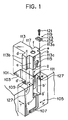
- the metal mold structure according to this embodiment generally includes a stationary metal mold 101, an insertion segment 105 and a gas venting unit 113.
- the stationary metal mold 101 has an upper surface portion confronting a movable metal mold (not shown) formed with a T-shaped opening 103 (in horizontal cross section) for receiving therein the insertion segment 105.
- a cruciform shaped opening (unit insertion recessed portion) 111 is provided into which the gas venting unit 113 is insertable.
- the T-shaped opening 103 is formed at an uppermost portion of the stationary metal mold 101 at a position close to the movable metal mold (not shown).
- a head or arm portion of the T-shaped opening 103 has a height equal to a height of the insertion segment 105.
- a leg portion of the T-shaped opening 103 has a height equal to a height of the gas venting unit 113.
- the arm portion of the T-shaped opening is provided with abutting surfaces d′ and f′.
- the insertion segment 105 is inserted into the arm portion of the T-shaped opening 103.
- the insertion segment 105 is formed with a T-shaped grooved portion 109.
- the cruciform shaped opening (unit insertion recessed portion) 111 is provided.
- the gas venting unit 113 is detachably inserted.
- a cylinder, a piston, a valve body and a valve seat such as those described in the "Background of the Invention" section are assembled.
- the gas venting unit 113 has a cruciform shape in a horizontal cross-section, and includes frontward/rearward positioning protrusions 113a, 113b and a lateral positioning protrusion 113c extending perpendicular to the protrusions 113a, 113b and in a direction from the stationary metal mold 101 to the movable metal mold (not shown).
- a width (in a direction X in Fig. 1) and a length (in a direction Y in Fig. 1) of the lateral positioning protrusion 113c are equal to a width and a length of the leg portion of the T-shaped grooved portion 109 of the insertion segment 105.
- the lateral positioning protrusion 113c has abutting surfaces a and b at lateral end faces thereof in the widthwise direction (X), and has a bottom abutting surface g.
- the frontward/rearward positioning protrusions 113a and 113b are formed with abutting surfaces e, f, and c, d.
- the frontward/rearward positioning protrusions 113a, 113b is equal to a distance between the abutting surface c′, e′ of the insertion segment 105 and the abutting surface d′, f′ of the T-shaped opening 103 of the stationary metal mold 101. Further, a distance between the lateral end surfaces of the frontward/rearward positioning protrusions 113a, 113b of the gas venting unit 113 (in the X direction in Fig. 1) is made slightly smaller than the length (in the X direction) of the head portion of the T-shaped groove 109 of the insertion segment 105.
- a width (X direction) and a length (Y direction) of the major portion of the gas venting unit 113 are made slightly smaller than the width and the length of the leg portion of the T-shaped opening 103 of the stationary metal mold 101. That is, an external contour of the gas venting unit 113 is substantially similar to the cruciform shaped opening 111 defined by the T-shaped opening 103 of the stationary metal mold 101 and the T-shaped grooved portion 109 of the insertion segment 105. With this arrangement, the gas venting unit 113 can be detachably and position-adjustably inserted with respect to the cruciform shaped opening 111.
- a valve hole 115 is opened, and at an upper face of the gas venting unit 113 an exhaust pipe attachment hole 117 is formed with which an exhaust pipe (not shown) is threadingly engageable.
- the exhaust pipe attachment hole 117 is in fluid communication with the valve hole 115 within the unit 113, and the above described valve body and the valve seat are provided at the communicating portion.
- a female thread is formed at an inner peripheral surface of the exhaust pipe attachment hole 117.
- the hole 117 is threadingly engageable with a pipe (see 31 in Fig. 8) which is connected to a vacuum pump (see 39 of Fig. 8) through an electromagnetic change-over valve (see 35 in Fig. 8).
- the metal mold structure of this embodiment is also provided with a fixing means 119 for fixing the gas venting unit 113 to the stationary metal mold 101.
- the fixing means 119 includes a bolt 121 and a plate member 125 formed with an elongated slot 123 to allow a shaft portion of the bolt 121 to pass therethrough.
- a pair of threaded bores 127 are formed for threading engagement with the bolt 121.
- the bolt 121 is threadingly engaged with the threaded bore 127 with interposing the plate member 125 therebetween.
- the plate member 125 has a sufficient area such that when the plate member 125 is fixed to the insertion segment 105 by the bolt 121, the plate member 125 abuts and depresses the top surface of the gas venting unit 113 for fixing the same 113 at the cruciform shaped opening or gas venting unit insertion recessed portion 111.
- the insertion segment 105 is fitted with the head portion of the T-shaped opening 103 of the stationary metal mold 101. Therefore, the cruciform shaped opening 111 is provided by the opening 103 and the T-shaped grooved portion 109 of the insertion segment 105.
- the gas venting unit 113 is fitted within the cruciform shaped opening 111. In this case, the positioning of the gas venting unit 113 with respect to rightward and leftward direction in Fig. 1 (X direction) is fulfilled by the surface abutment between the abutment surfaces a and b of the gas venting unit 113 and the abutment surfaces a′,b′ of the T-shaped grooved portion 109.
- Fig. 1 (Y direction) is fulfilled by the surface abutment between the abutment surfaces c, d, e, f and the abutment surfaces c′, d′, e′ and f′. Furthermore, the positioning with respect to the vertical direction is achieved by the abutment between the surfaces g of the gas venting unit 113 and the abutment surface g′.
- the gas venting unit 113 Upon completion of the fitting engagement of the gas venting unit 113 with the cruciform shaped opening 111, the gas venting unit 113 is urgedly held into the cruciform shaped opening 111 by the fixing means 119.
- the plate member 125 is positioned on the top surface of the insertion segment 105.
- the elongated slot 123 of the plate member 125 is aligned with the threaded hole 127 formed at the top portion of the insertion segment 105, and a part of the plate member 125 is also positioned on the top surface of the gas venting unit 113.
- the bolt 121 is inserted through the elongated lot 123, and is threadingly engaged with the threaded hole 127.
- the bolt 121 is unfastened for moving the plate member 123 away from the top surfaces of the gas venting unit 113. Then, a jig (described later) for removing the gas venting unit is employed for removing the unit 113 from the stationary metal mold 101.
- a metal mold structure according to a second embodiment of this invention will be described with reference to Fig. 2, wherein essential construction is substantially the same as that of the first embodiment, and therefore, fixing means (119 in Fig. 1) is omitted for simplicity.
- the primary difference between the first and the second embodiments resides in an external contour of the gas venting unit 113′ and a cruciform shaped opening 111′ which receives the unit 113′ therein.
- a stationary metal mold 101′ is formed with a T-shaped opening, and an insertion segment 105′ is formed with a T-shaped grooved portion similar to the first embodiment. Further, similar to the first embodiment, a cruciform shaped opening (unit insertion recessed portion) 111′ is defined by the T-shaped opening and the T-shaped grooved portion upon insertion of the insertion segment into the T-shaped opening of the stationary metal mold 101′.
- the gas venting unit 113′ has a cruciform shape in a horizontal cross-section similar to the first embodiment. That is, the unit 113′ includes a lateral positioning protrusion 113c′ extending toward a movable metal mold (not shown), and frontward/rearward positioning protrusions 113a′, 113b′ extending from a root portion of the protrusion 113c′ in a direction perpendicular thereto. As shown in Fig. 2, each of the positioning protrusions 113a′, 113b′ and 113c′ are so configured that widths of these protrusions are gradually small toward a bottom of the gas venting unit 113.
- a distance between abutment surfaces a and b, between abutment surfaces c and d and between abutment surfaces e and f are gradually small toward the bottom.
- corresponding portions of the cruciform shaped opening 111′ also have slanting abutment surfaces a′, b′, c′, d′, e′ and f′.
- the abutment surfaces a and b provided at the lateral positioning protrusion 113c′ are slantingly and symmetrically oriented so as to gradually reduce its width toward a bottom.
- abutment surfaces a′ and b′ at the T-shaped grooved portion formed in the insertion segment 105′ have inclination angles the same as those of the abutment surfaces a and b.
- abutment surfaces c and e of the frontward/rearward positioning protrusions 113a′ and 113b′ are also inclined, and corresponding abutment surfaces c′ and e′ formed at the insertion segment 105′ are inclined to mate with the inclination angles of the surfaces c and e.
- the abutment surfaces a, b, c, e and a′, b′, c′ and e′ are inclined with respect to a vertical plane.
- the abutment surfaces d and f of the frontward/rearward protrusions 113a′ and 113b′ and corresponding abutment surfaces d′ and f′ of the stationary metal mold 101′ can be slantingly formed.
- the abutment surfaces a, b, d and f and a′,b′, d′ and f′ are inclined.
- all abutment surfaces a through f and a′ through f′ can be inclined so as to provide a gradually thinner wall and thinner groove or opening toward a bottom.
- the lateral positioning protrusion 113c′ can be easily inserted into the unit insertion recessed portion 111′.
- the gas venting unit 113′ is brought into intimate contact with the unit insertion recessed portion 111′, similar to the first embodiment.
- the third embodiment is fundamentally similar to the first embodiment, and therefore, the fixing means 119 is omitted.
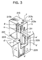
- the third embodiment has a cross-sectional structure of a gas venting unit 213 different from that of the first embodiment, and has a configuration of a unit insertion recessed portion defined by a T-shaped opening of a stationary metal mold 201 and a T-shaped grooved portion of an insertion segment 205, which configuration is different from that of the first embodiment.
- the stationary metal mold 201 is formed with a T-shaped opening 203 similar to the first embodiment.
- the insertion segment 209 formed with the T-shaped grooved portion 209 is inserted into the T-shaped opening 203.
- the figure T of the T-shaped groove portion 209 is oriented in a direction opposite to the first embodiment.
- abutment surfaces a′ and b′ are defined, and at one side of the head portion thereof, abutment surfaces c′ and d′ are defined as shown in Fig. 3.
- a leg portion of the T-shaped grooved portion 209 is directed in a direction the same as a leg portion of the T-shaped opening 203.
- a unit insertion recessed portion 211 is defined, in which two major sides of a rectangle have inwardly protruded rectangular notches so as to provide a generally H-shaped recess in a horizontal cross-section.
- the insertion segment 205 has surfaces, which confront the leg portion of the T-shaped opening 203, serving as abutment surfaces d′ and f′.
- the gas venting unit 213 has a horizontal cross-section the same as the generally H-shaped unit insertion recessed portion 211. That is, the unit 213 is formed with a pair of symmetrically arranged rectangular notches 213b and 213c at major sides thereof, where abutment surfaces c, d, e, and f are defined. Further, by the formation of the rectangular notches 213b and 213c, a T-shaped head portion 213a is provided, where abutment surfaces a and b are defined.
- the external contour of the gas venting unit 213 is substantially the same as the contour of the unit insertion recessed portion 211, and therefore, the gas venting unit 213 can be inserted into the unit insertion recessed portion 211.
- the assembly of the gas venting unit 213 into the unit insertion recessed portion 211 can be made in a manner similar to that of the foregoing embodiment.
- the positioning of the unit 213 in the lateral direction can be achieved by the surface abutments between the abutment surfaces a, b and the abutment surfaces a′ and b′.
- positioning in the frontward/backward direction is achievable by the surface abutments between the abutment surfaces c, d, e and f of the gas venting unit 213 and the abutment surfaces c′, d′, e′ and f′ of the insertion segment 205.
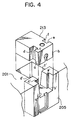
- a metal mold structure according to a fourth embodiment will next be described with reference to Fig. 4.
- the fourth embodiment would be substantially similar to the third embodiment except for inclination of abutment surfaces similar to the second embodiment. That is, as shown in Fig. 4, abutment surfaces a, b, d and f of a gas venting unit 213 are slanted with respect to a vertical plane so as to provide a gradually thin wall thickness toward its bottom. Further, abutment surfaces a′, b′, d′ and f′ of an insertion segment 205 are correspondingly slanted with respect to a vertical plane so as to matingly receive the gas venting unit. Alternatively, abutment surfaces c and e of the gas venting unit 213 can be slantingly formed, and abutment surfaces c′ and e′ of the insertion segment 205 can be slanted correspondingly.
- the separate gas venting unit can be detachably provided with respect to the stationary metal mold.
- the unit can be provided detachably with respect to the movable metal mold.
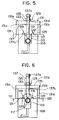
- a jig for removing the gas venting unit from the metal mold will be described with reference to Figs. 5 and 6.
- the jig is used for removing the gas venting unit 113 of the first embodiment.
- the jig 129 includes an inverted U-shaped or arch shaped jig body 131, a removing bolt 137 movably extending through the jig body 131, and a nut 135 threadingly engageable with the jig removing bolt 137.
- the jig body 131 includes two post portions 131b and 131c and a beam portion 131a bridging between the two post portions.
- the two post portions 131b and 131c are spaced away from each other by a distance at least greater than the lateral length of the lateral positioning protrusions 113a and 113b.
- a through hole 131d having an inner diameter greater than an outer diameter of a shaft portion 137b of the removing bolt 137.
- the removing bolt 137 (a bolt-like moving means) has a head portion 137a having a hexagonal shape and the shaft portion 137b integral with the head portion.
- the shaft portion 137b has a length greater than a length of the post portions 131b, 131c, and an end portion of the shaft 137b is formed with a male thread threadingly engageable with the threaded exhaust pipe attachment hole 117 formed at the top portion of the gas venting unit 113.
- the shaft portion 137b is formed with a male thread engageable with the nut 135 (means for driving the bolt-like moving means 137) mounted on the beam portion 131a.
- the nut 135 is rotatable about its axis but is stationarily held on the beam portion 131a. With this state, the shaft portion 137b is passed through the through hole 131d formed in the beam portion 131a.
- a washer 13 is interposed between the nut 135 and the beam portion 131a.
- the jig body 131 is mounted on the stationary metal mold 101 in such a manner that the post portions 131b and 131c are positioned outside the gas venting unit 113.
- the bolt 121 of the fixing means 119 is unfastened, and the plate member 121 is moved within a stroke range defined by a length of the elongated slot 123 so as to prevent mechanical interference between the plate member 125 and the gas venting unit 113, so that the gas venting unit 113 becomes removable from the metal mold.
- the removing bolt 137 is rotated, so that the tip end of the bolt 137 is brought into engagement with the exhaust pipe attachment hole 117 formed in the gas venting unit 113 as shown in Fig. 5. Then, the nut 135 is rotated for upwardly moving the bolt 137 in the axial direction thereof, to thereby removing the gas venting unit from the cruciform shaped opening 111.
- the gas venting unit 113 can be lifted in accordance with the upward movement of the removing bolt 137, to thereby remove the unit 113 from the cruciform shaped unit insertion recessed portion 111.
- the bolt 137 is disengaged from the exhaust pipe attachment hole 117 for maintenance, inspection and replacement of mechanical components with respect to the gas venting valve and the valve seat.
- the jig 129′ employs a lever member (means for driving the bolt-like moving means) 140 utilizing a principle of the lever and fulcrum.
- the lever member 140 lifts a removing bolt 137′ (bolt-like moving means) whose tip end portion 137b′ engages the exhaust pipe attachment hole 117 of the gas venting unit 113.
- an inverted U-shaped jib body 131 is provided similar to the jig of the first example.
- the jig body 131 has a beam portion 131a whose central portion is formed with a through hole 131d through which a shaft portion 137b′ of the removing bolt 137′ extends.
- the shaft portion 137b′ has a threaded portion only at a tip end portion thereof for engagement with the exhaust pipe attachment hole 117 of the gas venting unit 113.
- the lever member 140 serving as means for driving the bolt-like moving means 137′ has a L-shape configuration as shown in Fig. 7.
- the lever member 140 has an acting arm 140a, a power-applied arm 140b and a fulcrum point 140c.
- the acting arm 140a is formed with a notched recess portion 140d engageable with the shaft portion 137b′ and abuttable on a head portion 137a′ of the bolt 137′.
- a opening width of the notched recess 140d is larger than the diameter of the shaft portion 137b′, and smaller than the diameter of the head portion 137a′.
- the acting arm 140a of the lever member 140 is positioned immediately below the head portion 137a′ and above the beam portion 131a of the jib body 131, and the shaft portion 137b′ of the bolt 137′ is inserted into the notched recess 140d. After the engagement of the notched recess 140d with the shaft portion 137b′, an upper surface of the acting arm 140a abuts the lower surface of the head portion 137a′, and the fulcrum point 140c abuts the upper surface of the beam portion 131a of the jig body 131.
- the jig body 131 is mounted on the stationary metal mold 101 in such a manner that the post portions do not ride on the gas venting unit 113. Further, the fixing means 119 is unfastened from the gas venting unit 113, and the tip end portion of the shaft portion 137b′ of the removing bolt 137′ is brought into threading engagement with the exhaust pipe attachment hole 117 of the gas venting unit 113. Then, the notched recess portion 140d at the acting arm 140a of the lever member 140 is engaged with the shaft portion 137b′, and the power applied portion 140b is depressed toward the stationary metal mold 101 as indicated by an arrow shown in Fig. 7.
- the acting arm 140a urges the head portion 137a′ of the bolt 137′ upwardly, so that the shaft portion 137b′ is also lifted upwardly.
- the gas venting unit 113 engaged with the bolt 137′ can be moved upwardly whereupon the gas venting unit 113 can be removed from the cruciform shaped unit insertion recessed portion 111.
- a jack is available.
- the jig 129 or 129′ as described above is used for removing the gas venting unit of the first embodiment.
- the jig is also apparently available for the metal mold structures according to the second through fourth embodiments.
- the insertion segment is separably and detachably provided with respect to the T-shaped opening of the metal mold and since the gas venting unit is provided detachably with respect to the unit insertion recessed portion defined by the T-shaped opening and the T-shaped grooved portion of the insertion segment, maintenance and inspection such as a removal of the molten metal flash and replacement works are facilitated because of the easy detachment of the gas venting arrangement and the insertion segment from the metal mold.
- the T-shaped opening and the T-shaped grooved portion are formed in the metal mold and the insertion segment, respectively, and these T-shaped opening and grooved portion are combined together.
- the unit insertion recessed portion can be easily formed, to thereby facilitate manufacture of the metal mold structure.
- insertion work of the gas venting unit into the unit insertion recessed portion can be easily achieved by forming the slanted surfaces which define the external contour of the gas venting unit, which slanted surface provide a bottom-thin, top-thick arrangement of the gas venting unit and by forming the corresponding slanted surfaces at the unit insertion recessed portion which receives therein the gas venting unit.
- the gas venting unit can be easily removed from the unit insertion recessed portion by mere rotation of the nut or by mere manipulation of the lever member. Therefore, even if deformation occurs in the gas venting unit and the stationary or movable metal mold, or even if molten flash is provided at a portion between the gas venting unit and one of the stationary and movable metal molds, the gas venting unit can be easily detached. Accordingly, maintenance, inspection and replacement work to the gas venting unit can further be facilitated to thus improve working efficiency.
Landscapes
- Engineering & Computer Science (AREA)
- Mechanical Engineering (AREA)
- Moulds For Moulding Plastics Or The Like (AREA)
Claims (9)
- Eine Metall-Gußform-Anordnung in einer Spritzguß-Vorrichtung, wobei die Metall-Gußform-Anordnung eine Metall-Gußform, in der ein Formhohlraum gebildet ist, und eine Gasentlüftungsanordnung umfaßt, in der ein Gasentlüftungsdurchgang mit dem Formhohlraum in Verbindung steht und der Gasentlüftungsdurchgang selektiv vom Äußeren mittels eines Gasentlüftungsventilmittels abgeschlossen ist; wobei die Metall-Gußform-Anordnung gekennzeichnet ist durch:Eine Metall-Gußform (101,101',201), deren eine Oberfläche eine Trennfläche bildet und mit einer oberen Öffnung (103,203) an einer Seite der Trennfläche ausgebildet ist;eine Gasentlüftungseinheit (113,113',213), die separat von der Metall-Gußform vorgesehen ist und eine vorgegebene äußere Kontur aufweist, wobei die Gasentlüftungsventilmittel in der Gasentlüftungseinheit angeordnet sind;ein Einsatzsegment (105,105',205), das passend in einen Teil der oberen Öffnung einsetzbar ist, wobei ein Ausnehmungsabschnitt (111, 111',211) zum Einsetzen der Einheit durch die obere Öffnung und das Einsatzsegment gebildet wird, wenn das Einsatzsegment dort eingesetzt wird, und wobei der Ausnehmungsabschnitt zum Einsetzen der Einheit eine Konfiguration aufweist, die im wesentlichen mit der äußeren Kontur der Gasentlüftungseinheit zur Aufnahme der Einheit in den Ausnehmungsabschnitt zum Einsetzen der Einheit übereinstimmt; undein Befestigungsmittel (119) zur Befestigung der Gasentlüftungseinheit in den Ausnehmungsabschnitt zum Einsetzen der Einheit.
- Die Metall-Gußform-Anordnung nach Anspruch 1, bei der das Einsatzsegment (105, 105', 205) mit einem oberen Nutenabschnitt (109, 209) gebildet ist, wobei eine Kombination des oberen Nutenabschnitts und der oberen Öffnung den Ausnehmungsabschnitt zum Einsetzen der Einheit bilden.
- Die Metall-Gußform-Anordnung nach Anspruch 1 oder 2, bei der die Gasentlüftungseinheit wenigstens zwei symmetrische Anschlag- bzw. Anlageoberflächen (a,b oder c,e oder d,f) aufweist, die sich in Bezug auf eine vertikale Ebene schräg erstrecken und eine oben starke, unten schmale bzw. dünne Masse vorsehen, wobei die symmetrischen Anlageoberflächen einen Teil der äußeren Kontur der Gasentlüftungseinheit bilden, und bei der der Ausnehmungsabschnitt zum Einsetzen der Einheit wenigstens zwei symmetrische Oberflächen (a'b' oder c'e' oder d'f') aufweist, die jeweils Neigungswinkel aufweisen, die den Neigungswinkeln der entsprechenden beiden symmetrischen Anlageoberflächen entsprechen.
- Die Metall-Gußform-Anordnung nach Anspruch 1 oder 2, bei der die Gasentlüftungseinheit (113, 113') im Horizontalschnitt Kreuzform aufweist und bei der der Ausnehmungsabschnitt zum Einsetzen der Einheit (111, 111') im Horizontalschnitt eine entsprechende Kreuzform aufweist.
- Die Metall-Gußform-Anordnung nach Anspruch 1 oder 2, bei der die Gasentlüftungseinheit (213) im Horizontalschnitt im wesentlichen H-Form aufweist und bei der der Ausnehmungsabschnitt zum Einsetzen der Einheit (211) im Horizontalschnitt eine entsprechende H-Form aufweist.
- Eine Spritzgußvorrichtung, umfassend eine Metall-Gußform-Anordnung und eine Spann- bzw. Setzeinrichtung, wobei die Metall-Gußform-Anordnung gekennzeichnet ist durch:Eine Metall-Gußform (101,101',201), deren eine Oberfläche eine Trennfläche bildet und mit einer oberen Öffnung (103, 203) an einer Seite der Trennfläche ausgebildet ist, wobei die Metall-Gußform mit einem Formenhohlraum und einer Gasentlüftungseinheit in Verbindung damit ausgebildet ist;eine Gasentlüftungseinheit (113,113',213), die separat von der Metall-Gußform vorgesehen ist und eine vorgegebene äußere Kontur aufweist, wobei die Gasentlüftungsventilmittel in sich ein Gasentlüfungsventilmittel aufnehmen, das den Gasentlüftungsdurchgang selektiv verschließt und einen oberen Abschnitt aufweist, der mit einem Abluftleitungsbefestigungsloch (117) ausgebildet ist;ein Einsatzsegment (105,105',205), das passend in einen Teil der oberen Öffnung einsetzbar ist, wobei ein Ausnehmungsabschnitt (111, 111',211) zum Einsetzen der Einheit durch die obere Öffnung und das Einsatzsegment gebildet wird, wenn das Einsatzsegment dort eingesetzt wird, und wobei der Ausnehmungsabschnitt zum Einsetzen der Einheit eine Konfiguration aufweist, die im wesentlichen mit der äußeren Kontur der Gasentlüftungseinheit zur Aufnahme der Einheit in den Ausnehmungsabschnitt zum Einsetzen der Einheit übereinstimmt; undein Befestigungsmittel (119) zur Befestigung der Gasbelüftungseinheit in dem Ausnehmungsabschnitt zum Einsetzen der Einheit; undwobei die Setzeinrichtung ausgebildet ist, um eine Gasentlüftungseinheit aus dem Ausnehmungsabschnitt zum Einsetzen der Einheit einer Metall-Gußform-Anordnung zu entfernen, und umfaßt:einen Spann- oder Setzkörper (131), der auf der Metall-Gußform gegenüber dem Abluftleitungsbefestigungsloch (117) angebracht ist, wobei der Setzkörper mit einem Durchgangsloch (131d), das mit dem Abluftleitungsbefestigungsloch ausgerichtet werden kann, ausgebildet ist;ein bolzenartiges Bewegungsmittel (137, 137'), umfassend einen Kopfabschnitt (137a, 137a') und einen damit integral ausgebildeten und wenigstens am Endabschnitt als Gewindeabschnitt ausgebildeten Schaftabschnitt (137b, 137b'), wobei der Schaftabschnitt durch das Durchgangsloch (131d) hindurchführbar ist und der Gewindeabschnitt schraubbar mit dem Abluftleitungsbefestigungsloch verbindbar ist; undMittel (135,140) zum Antreiben der bolzenartigen Bewegungsmittel, wobei die Antriebsmittel zwischen den bolzenartigen Bewegungsmitteln und dem Setzkörper angeordnet sind und zum Aufwärtsbewegen der bolzenartigen Bewegungsmittel angetrieben werden, um dadurch die Gasentlüftungseinheit anzuheben, die mit den bolzenartigen Bewegungsmitteln zum Entfernen der Gasentlüftungseinheit von dem Ausnehmungsabschnitt zum Einsetzen der Einheit in Eingriff steht.
- Die Vorrichtung nach Anspruch 6, bei der der Schaftabschnitt (137b) der bolzenartigen Bewegungsmittel mit Gewinde entlang seiner Länge ausgebildet ist und bei der das Antriebsmittel eine Mutter (135) umfaßt, die drehbar um ihre Achse und unbeweglich in einer dazu axialen Richtung ist, wobei die Mutter schraubbar mit dem Gewindeabschnitt in Eingriff zu bringen ist, um die bolzenartigen Bewegungsmittel zusammen mit der Gasentlüftungseinheit durch Drehung der Mutter nach oben zu heben.
- Die Vorrichtung nach Anspruch 6, bei der das Antriebsmittel ein L-förmiges Hebelelement (140), das einen Arbeitsarm (140a) aufweist, der mit dem Schaftabschnitt (137b') in Eingriff zu bringen ist und gegen den Kopfabschnitt (137a') zur Anlage gelangen kann, einen Abschnitt (140b), auf den Kraft ausgeübt wird, und einen Drehabschnitt (140c) umfaßt, der auf dem Setzkörper (131) angeordnet ist, wobei der wirksame Arm (140a) den Kopfabschnitt bei Kraftanwendung auf den kraftbeaufschlagten Abschnitt (140b) nach oben gedrängt wird.
- Die Vorrichtung nach Anspruch 6, bei der der Spann- oder Setzkörper (131) umfaßt:ein Paar Pfostenabschnitte (131b, 131c), die aufrecht auf der Metall-Gußform angeordnet und versetzt von der Gasentlüftungseinheit angeordnet sind, die in den Ausnehmungsabschnitt zum Einsetzen der Einheit eingeführt ist; undeinen das Pfostenabschnittspaar überbrückenden Balkenabschnitt (131a), wobei das Durchgangsloch in dem Balkenabschnitt gebildet ist und die Antriebsmittel auf dem Balkenabschnitt angebracht sind.
Applications Claiming Priority (2)
| Application Number | Priority Date | Filing Date | Title |
|---|---|---|---|
| JP245788/90 | 1990-09-14 | ||
| JP24578890 | 1990-09-14 |
Publications (3)
| Publication Number | Publication Date |
|---|---|
| EP0475654A2 EP0475654A2 (de) | 1992-03-18 |
| EP0475654A3 EP0475654A3 (en) | 1992-12-09 |
| EP0475654B1 true EP0475654B1 (de) | 1997-01-02 |
Family
ID=17138839
Family Applications (1)
| Application Number | Title | Priority Date | Filing Date |
|---|---|---|---|
| EP19910308033 Expired - Lifetime EP0475654B1 (de) | 1990-09-14 | 1991-09-02 | Druckgussform mit Entgasungsanordnung und Ausbauvorrichtung für die Entgasungsanordnung |
Country Status (1)
| Country | Link |
|---|---|
| EP (1) | EP0475654B1 (de) |
-
1991
- 1991-09-02 EP EP19910308033 patent/EP0475654B1/de not_active Expired - Lifetime
Also Published As
| Publication number | Publication date |
|---|---|
| EP0475654A2 (de) | 1992-03-18 |
| EP0475654A3 (en) | 1992-12-09 |
Similar Documents
| Publication | Publication Date | Title |
|---|---|---|
| EP2829354B1 (de) | Spannvorrichtung | |
| US4463793A (en) | Vacuum die casting machine | |
| JPS646221Y2 (de) | ||
| US5423369A (en) | Apparatus for and method of vacuum casting | |
| US5476205A (en) | Make and break head valve assembly | |
| JPH08284B2 (ja) | 射出成形機におけるガス抜き装置の金型構造とガス抜き装置本体取り出し用治具 | |
| EP0475654A2 (de) | Druckgussform mit Entgasungsanordnung und Ausbauvorrichtung für die Entgasungsanordnung | |
| CN218656318U (zh) | 一种模具的切换机构及冲压模具 | |
| CN109927242B (zh) | 一种多色模具的脱模机构 | |
| JP2802359B2 (ja) | 封止部材 | |
| CN219004357U (zh) | 一种带有自动取件装置的冲压模具 | |
| CN218192481U (zh) | 一种压铸零件成型模具 | |
| JPH09225855A (ja) | 打込機の駆動制御装置 | |
| JPH084909B2 (ja) | 射出成形機におけるガス抜き装置の弁構造 | |
| JP3187884B2 (ja) | 打撃工具のメインバルブのシール装置 | |
| CN219152781U (zh) | 一种钉枪击发状态切换结构和钉枪 | |
| JPH065006Y2 (ja) | 真空ダイカスト装置 | |
| KR860002407Y1 (ko) | 사출금형의 2단 취출장치 | |
| JPS6121739B2 (de) | ||
| CN116653177A (zh) | 一种多开模动作顺序可控的模具及方法 | |
| JPS5847292Y2 (ja) | 開閉装置の操作シリンダ | |
| CN212764283U (zh) | 一种模具顶出结构 | |
| JPH0556364U (ja) | 打込機のアタッチメント | |
| JPS6341147Y2 (de) | ||
| CN210791910U (zh) | 一种侧抽芯连带反锁装置及注塑系统 |
Legal Events
| Date | Code | Title | Description |
|---|---|---|---|
| PUAI | Public reference made under article 153(3) epc to a published international application that has entered the european phase |
Free format text: ORIGINAL CODE: 0009012 |
|
| AK | Designated contracting states |
Kind code of ref document: A2 Designated state(s): FR GB IT |
|
| PUAL | Search report despatched |
Free format text: ORIGINAL CODE: 0009013 |
|
| AK | Designated contracting states |
Kind code of ref document: A3 Designated state(s): FR GB IT |
|
| 17P | Request for examination filed |
Effective date: 19930528 |
|
| GRAG | Despatch of communication of intention to grant |
Free format text: ORIGINAL CODE: EPIDOS AGRA |
|
| 17Q | First examination report despatched |
Effective date: 19960311 |
|
| GRAH | Despatch of communication of intention to grant a patent |
Free format text: ORIGINAL CODE: EPIDOS IGRA |
|
| GRAH | Despatch of communication of intention to grant a patent |
Free format text: ORIGINAL CODE: EPIDOS IGRA |
|
| GRAA | (expected) grant |
Free format text: ORIGINAL CODE: 0009210 |
|
| AK | Designated contracting states |
Kind code of ref document: B1 Designated state(s): FR GB IT |
|
| PG25 | Lapsed in a contracting state [announced via postgrant information from national office to epo] |
Ref country code: IT Free format text: LAPSE BECAUSE OF FAILURE TO SUBMIT A TRANSLATION OF THE DESCRIPTION OR TO PAY THE FEE WITHIN THE PRESCRIBED TIME-LIMIT;WARNING: LAPSES OF ITALIAN PATENTS WITH EFFECTIVE DATE BEFORE 2007 MAY HAVE OCCURRED AT ANY TIME BEFORE 2007. THE CORRECT EFFECTIVE DATE MAY BE DIFFERENT FROM THE ONE RECORDED. Effective date: 19970102 Ref country code: FR Effective date: 19970102 |
|
| EN | Fr: translation not filed | ||
| PLBE | No opposition filed within time limit |
Free format text: ORIGINAL CODE: 0009261 |
|
| STAA | Information on the status of an ep patent application or granted ep patent |
Free format text: STATUS: NO OPPOSITION FILED WITHIN TIME LIMIT |
|
| 26N | No opposition filed | ||
| REG | Reference to a national code |
Ref country code: GB Ref legal event code: 746 Effective date: 19980602 |
|
| REG | Reference to a national code |
Ref country code: GB Ref legal event code: IF02 |
|
| PGFP | Annual fee paid to national office [announced via postgrant information from national office to epo] |
Ref country code: GB Payment date: 20100901 Year of fee payment: 20 |
|
| REG | Reference to a national code |
Ref country code: GB Ref legal event code: PE20 Expiry date: 20110901 |
|
| PG25 | Lapsed in a contracting state [announced via postgrant information from national office to epo] |
Ref country code: GB Free format text: LAPSE BECAUSE OF EXPIRATION OF PROTECTION Effective date: 20110901 |