EP0475979B1 - Diaphragm valve - Google Patents
Diaphragm valve Download PDFInfo
- Publication number
- EP0475979B1 EP0475979B1 EP90908498A EP90908498A EP0475979B1 EP 0475979 B1 EP0475979 B1 EP 0475979B1 EP 90908498 A EP90908498 A EP 90908498A EP 90908498 A EP90908498 A EP 90908498A EP 0475979 B1 EP0475979 B1 EP 0475979B1
- Authority
- EP
- European Patent Office
- Prior art keywords
- valve
- diaphragm
- container
- outlet
- inlet
- Prior art date
- Legal status (The legal status is an assumption and is not a legal conclusion. Google has not performed a legal analysis and makes no representation as to the accuracy of the status listed.)
- Expired - Lifetime
Links
- 239000012530 fluid Substances 0.000 claims description 11
- 238000007789 sealing Methods 0.000 claims description 10
- 239000000645 desinfectant Substances 0.000 claims description 3
- 238000004659 sterilization and disinfection Methods 0.000 abstract description 10
- 238000005070 sampling Methods 0.000 abstract description 9
- 230000001954 sterilising effect Effects 0.000 abstract description 9
- 238000004140 cleaning Methods 0.000 abstract description 2
- 238000000855 fermentation Methods 0.000 description 8
- 230000004151 fermentation Effects 0.000 description 8
- 239000000463 material Substances 0.000 description 4
- 230000015572 biosynthetic process Effects 0.000 description 2
- 210000004027 cell Anatomy 0.000 description 2
- 238000010276 construction Methods 0.000 description 2
- 238000010438 heat treatment Methods 0.000 description 2
- 238000011065 in-situ storage Methods 0.000 description 2
- 239000007788 liquid Substances 0.000 description 2
- 244000005700 microbiome Species 0.000 description 2
- 238000004062 sedimentation Methods 0.000 description 2
- 238000003466 welding Methods 0.000 description 2
- 238000004458 analytical method Methods 0.000 description 1
- 230000004888 barrier function Effects 0.000 description 1
- 235000013361 beverage Nutrition 0.000 description 1
- 230000009172 bursting Effects 0.000 description 1
- 239000012141 concentrate Substances 0.000 description 1
- 238000011109 contamination Methods 0.000 description 1
- 230000000694 effects Effects 0.000 description 1
- 238000010353 genetic engineering Methods 0.000 description 1
- 238000007689 inspection Methods 0.000 description 1
- 210000004962 mammalian cell Anatomy 0.000 description 1
- 239000002184 metal Substances 0.000 description 1
- 238000000034 method Methods 0.000 description 1
- 239000000203 mixture Substances 0.000 description 1
- 239000004033 plastic Substances 0.000 description 1
- 229920003023 plastic Polymers 0.000 description 1
- 239000012858 resilient material Substances 0.000 description 1
- 239000005060 rubber Substances 0.000 description 1
- 229910001220 stainless steel Inorganic materials 0.000 description 1
- 239000010935 stainless steel Substances 0.000 description 1
- 238000003756 stirring Methods 0.000 description 1
- 239000000725 suspension Substances 0.000 description 1
Images


Classifications
-
- F—MECHANICAL ENGINEERING; LIGHTING; HEATING; WEAPONS; BLASTING
- F16—ENGINEERING ELEMENTS AND UNITS; GENERAL MEASURES FOR PRODUCING AND MAINTAINING EFFECTIVE FUNCTIONING OF MACHINES OR INSTALLATIONS; THERMAL INSULATION IN GENERAL
- F16K—VALVES; TAPS; COCKS; ACTUATING-FLOATS; DEVICES FOR VENTING OR AERATING
- F16K7/00—Diaphragm valves or cut-off apparatus, e.g. with a member deformed, but not moved bodily, to close the passage ; Pinch valves
- F16K7/12—Diaphragm valves or cut-off apparatus, e.g. with a member deformed, but not moved bodily, to close the passage ; Pinch valves with flat, dished, or bowl-shaped diaphragm
-
- C—CHEMISTRY; METALLURGY
- C12—BIOCHEMISTRY; BEER; SPIRITS; WINE; VINEGAR; MICROBIOLOGY; ENZYMOLOGY; MUTATION OR GENETIC ENGINEERING
- C12M—APPARATUS FOR ENZYMOLOGY OR MICROBIOLOGY; APPARATUS FOR CULTURING MICROORGANISMS FOR PRODUCING BIOMASS, FOR GROWING CELLS OR FOR OBTAINING FERMENTATION OR METABOLIC PRODUCTS, i.e. BIOREACTORS OR FERMENTERS
- C12M37/00—Means for sterilizing, maintaining sterile conditions or avoiding chemical or biological contamination
- C12M37/04—Seals
-
- G—PHYSICS
- G01—MEASURING; TESTING
- G01N—INVESTIGATING OR ANALYSING MATERIALS BY DETERMINING THEIR CHEMICAL OR PHYSICAL PROPERTIES
- G01N1/00—Sampling; Preparing specimens for investigation
- G01N1/02—Devices for withdrawing samples
- G01N1/10—Devices for withdrawing samples in the liquid or fluent state
- G01N1/20—Devices for withdrawing samples in the liquid or fluent state for flowing or falling materials
- G01N1/2035—Devices for withdrawing samples in the liquid or fluent state for flowing or falling materials by deviating part of a fluid stream, e.g. by drawing-off or tapping
-
- Y—GENERAL TAGGING OF NEW TECHNOLOGICAL DEVELOPMENTS; GENERAL TAGGING OF CROSS-SECTIONAL TECHNOLOGIES SPANNING OVER SEVERAL SECTIONS OF THE IPC; TECHNICAL SUBJECTS COVERED BY FORMER USPC CROSS-REFERENCE ART COLLECTIONS [XRACs] AND DIGESTS
- Y10—TECHNICAL SUBJECTS COVERED BY FORMER USPC
- Y10T—TECHNICAL SUBJECTS COVERED BY FORMER US CLASSIFICATION
- Y10T137/00—Fluid handling
- Y10T137/4238—With cleaner, lubrication added to fluid or liquid sealing at valve interface
- Y10T137/4245—Cleaning or steam sterilizing
- Y10T137/4266—Steam sterilizing
Definitions
- the invention relates to diaphragm valves designed to be fitted in a cut out of a container wall and comprising a valve housing having a valve inlet channel communicating with the fluid inside the container, a valve outlet channel for extracting fluid from the inside of the container, and valve seats surrounding the valve inlet part, flexible diaphragm mounted movably for shifting between an open and a closed position, and actuator means for shifting the diaphragm between the open and a closed position.
- valves are suited for both vertical and horizontal mounting in a container wall for use both as a valve for taking samples and/or a drainage valve under conditions where strict hygiene and containment must be observed, such as in fermentation processes, biological experimentation and the like.
- a valve is for instance disclosed in French patent No. 926,440 ( LAGUILHARRE).
- Valves of this type are particularly used within the food, beverage, and medical industries where demands on hygiene are great.
- the presence of a diaphragm which separates the medium from the manoeuvring part of the valve makes this valve particularly suited for use in a sterile environment.
- the diaphragm valve known from French patent No. 927,290 is another example of such a valve where the diaphragm rests on a valve seat being designed in a rib extending across the flow channel.
- This rib is provided with several pockets and corners in which the medium may be deposited so that the valve firstly is difficult to clean and sterilize, and secondly, will cause an uneven sampling, both since the uneven flow conditions cause an uneven mixing of the medium, and due to the risk of stagnant media. Also, the bad flow conditions cause a great loss of pressure.
- French patent No. 1,200,849 (Nuyens) is another example of such a valve.
- the valve of that patent cannot be mounted so that the diaphragm in closed position forms a closure against the container wall and partly becomes an integral part thereof, but a stagnant container volume (dead volume or leg) will be formed in the valve inlet.
- valve cannot be used for sampling from suspended fluids, since the stagnant volume of fluid in the valve inlet will have a higher concentration of suspended material than in the container where the suspension is kept in mixture by stirring means.
- valves used as a sterilizable drain valve can be seen in not prepublished US Patent No. 4,836,236 (Ladisch).
- the valve according to that patent also exhibits a valve chamber giving problems in connection with sterilisation and complete drainage of said chamber.
- that type of valve is in no way suitable for vertical mounting for taking samples from the content of a tank.
- a further disadvantage with many of the prior art diaphragm valves is that the diaphragm material during operation must be deformed considerably increasing the risk of cracks in or bursting of the diaphragm.
- the substantially flush-sealing diaphragm valves of the invention are especially directed at use in fermentation tanks and the like where genetically engineered microorganisms or mammalian cells are cultivated and where full containment is demanded with a view to protection of the external environment.
- valve housing inlet and outlet and the diaphragm which come into contact with the fluid, form a fluid-contacted volume being constructed by means of simple geometric forms ensuring optimal "sanitary standard" in an uncomplicated cleaning process. Remaining material, if any, which cannot be washed out of the valve forms a contamination risk even if the valve is sterilized with superheated steam before the fermentation cycle is initiated.
- valve housing has a base by which it is attached to the container wall, the inlet channel being partly defined by an outwards slanting outer part of a flange of the valve housing and partly by a bottom wall of the valve housing slanting outwards from the opposite side, the outlet channel being defined partly by the opposite side of the bottom wall and partly by an outer part of the flange which defines the valve housing at the top, whereby the valve inlet channel also functions as a container outlet port or opening; the surface of the diaphragm facing the inside of the container in the closed position is geometrically close to the inner outline of the container wall, and abuts directly against the valve seats surrounding the valve inlet channel and valve outlet channel simultaneously closing the ports of both the valve inlet and outlet channels with uniform deformation of the diaphragm.
- valve seats are so shaped that seen together as a whole they form the contour of a section of the surface of a sphere having its centre outside the container, whereby the diaphragm in the closed position takes form as a sector of a corresponding spherical surface sealing against the seats.
- the inlet channel of the valve housing may form a funnel-shaped opening on to the inlet of the valve seat.
- an opening and an optional outlet for steam or similar disinfectant open on the outlet channel of the valve housing.
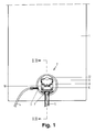
- valve of the invention is shown in Figs 1 to 4 in embodiments which will be discussed in detail below.
- the valve of the invention is a diaphragm valve especially suited for welding into a side or the bottom of a container depending on its mode of use.
- the valve of the invention comprises:
- valve of the invention is characteristic in that the valve housing forms an integral part of the container, whereby the valve inlet port also functions as a container outlet port or opening, and the surface of the diaphragm facing the inside of the container in the closed position is geometrically close to the inner outline of the container.
- the valve is further characteristic in that the diaphragm closes and abuts directly against valve seats surrounding the valve inlet port (container outlet) and valve outlet port simultaneously so that the deformation of the diaphragm is uniform.
- the diaphragm further works in such a way that it seals the valve without the need for special sealing means in connection with the mechanism provided for moving the diaphragm between open and closed positions.
- the valve housing is designed so that it when being mounted horizontally can discharge the contents of the container completely and also empty the valve housing completely when the valve is closed again.
- valve housing Mounted vertically the valve housing can be drained completely in the valve inlet as well as in the valve outlet, this allows sampling of fluid that is 100% representative of the contents of the container.
- valve housing and position of diaphragm according to the invention as described further below give considerable sterilization safety upon use of superheated steam or of liquid under pressure in the container as stagnant medium in a dead volume at any position in the valve housing is effectively avoided.
- Open sterilization is also optimal both to the valve inlet and the valve outlet, as well as to the inner surfaces due to the simple geometry.
- the geometry of the valve housing preferably is so that the seats for the diaphragm, seen together as a whole as in Fig. 4, forms the contour of a section of the surface of a sphere having its centre outside the container.
- the diaphragm in the closed position takes form as a sector of a corresponding spherical surface sealing against the seats.
- the diaphragm will shut off the inlet and outlet uniformly when the diaphragm is moved towards the seat which produces an advantageous flow characteristic and a uniform deformation of the diaphragm minimizing wear on both the valve housing and diaphragm.
- the inlet channel is narrowing toward the valve seat, as seen from the inside of the container to form a funnel-shaped channel, the best possible flow conditions are obtained for the inflow as well as for the outflow with practically no risk of stagnant media.
- the diaphragm sealing concentrates the heating effect to the valve housing and container as the diaphragm thermally insulates the remaining parts of the valve therefrom.
- the valve housing can be made by material of uniform dimensions ensuring an even heating (and thereby expansion) when sterilization is performed.
- the drawing shows an example of a preferred embodiment of a valve 2 being provided with an upper part for manual operation of the diaphragm.
- a manual spindle mechanism is indicated, but it is of course within the scope of the invention to replace this upper part by another type of actuator such as a lever.
- the mechanism may of course also be remotely controlled by electrical or pneumatic means through, or through a motor drive or the like.
- the upper part comprises a flange 18 which is open at the centre for a spindle (not shown) which interlocks with an attachment piece 17 on the back of a diaphragm 16.
- a spindle casing 20 is secured to the flange 18, and an opening indicator 21 is secured at one end of the spindle casing 20.
- a handwheel 22 is attached which by turning moves the spindle and thus the diaphragm 16, 17.
- the valve 2 comprises a valve housing 9 which is for instance made of stainless steel and provided with a base which, in the shown example, is designed so that the valve housing can be attached to a cut-out in a container wall 1 by means of a welded seam 6.
- the inlet channel 13 is defined partly by an outwards slanting outer part of a flange 8 of the valve housing 9 and partly by a bottom wall 10 of the valve housing 9 slanting outwards from the opposite side.
- An outlet channel 15 is defined partly by the opposite side of the bottom wall 10 and partly by an outer part 15 of the flange which defines the valve housing at the top.
- the outlet channel 15 is connected to a pipe 5 by a welding 7. Moreover, a pipe 4 opens into an opening 3 in the outlet channel 15 through which opening steam or the like for sterilization of this part of the system can be added. If there is no steam outlet through the outlet pipe 5, an outlet opening (not shown) can be arranged for the steam. These openings 3 can be provided with barriers (not shown) for the formation of a closed pipe system.
- the diaphragm 16, 17 can be made of any suitable resilient material such as reinforced rubber, plastics, metal or the like, depending on the type of medium.
- the diaphragm 16, 17 is placed on the outside of the flange 8 of the valve housing 9 and is secured by means of bolts 19 extending through the flange 18 of the upper part through the diaphragm 16 into thread holes in the housing 9. This facilitates an easy disassembly of the parts for purposes of inspection and replacement of the diaphragm, if so required.
- valve seats are designed partly as a circular seat 12 extending around inlet 13 as well as outlet 14, and partly as a seat 11 arranged in the bottom wall 10 separating the inlet 13 from the outlet 14.
- valve seats 11, 12 have such a geometrical shape that they substantially define a sector of a sphere.
- optimum contact is obtained to the moving part of the diaphragm 16 from its outer to its inner rim in that the diaphragm will assume a shape corresponding to a spherical segment once it is pressed in for abutment on the valve seats for closure of the valve, as shown in fig. 2.
- valve has optimal flow conditions, and the loss of pressure through the valve will be held at a minimum.
Landscapes
- Life Sciences & Earth Sciences (AREA)
- Health & Medical Sciences (AREA)
- Engineering & Computer Science (AREA)
- General Engineering & Computer Science (AREA)
- Chemical & Material Sciences (AREA)
- Wood Science & Technology (AREA)
- Organic Chemistry (AREA)
- Bioinformatics & Cheminformatics (AREA)
- General Health & Medical Sciences (AREA)
- Biochemistry (AREA)
- Zoology (AREA)
- Genetics & Genomics (AREA)
- Immunology (AREA)
- Microbiology (AREA)
- Biotechnology (AREA)
- Biomedical Technology (AREA)
- Molecular Biology (AREA)
- Mechanical Engineering (AREA)
- Hydrology & Water Resources (AREA)
- Physics & Mathematics (AREA)
- Analytical Chemistry (AREA)
- General Physics & Mathematics (AREA)
- Sustainable Development (AREA)
- Pathology (AREA)
- Lift Valve (AREA)
- Magnetically Actuated Valves (AREA)
- Apparatus For Disinfection Or Sterilisation (AREA)
- Sampling And Sample Adjustment (AREA)
- Apparatus Associated With Microorganisms And Enzymes (AREA)
- Valve Housings (AREA)
- Fluid-Driven Valves (AREA)
- Superconductors And Manufacturing Methods Therefor (AREA)
- Control Of The Air-Fuel Ratio Of Carburetors (AREA)
- Investigating Or Analysing Biological Materials (AREA)
- Multiple-Way Valves (AREA)
Applications Claiming Priority (2)
| Application Number | Priority Date | Filing Date | Title |
|---|---|---|---|
| DK247989A DK247989D0 (da) | 1989-05-22 | 1989-05-22 | Membranventil |
| DK2479/89 | 1989-05-22 |
Publications (2)
| Publication Number | Publication Date |
|---|---|
| EP0475979A1 EP0475979A1 (en) | 1992-03-25 |
| EP0475979B1 true EP0475979B1 (en) | 1993-05-12 |
Family
ID=8112675
Family Applications (1)
| Application Number | Title | Priority Date | Filing Date |
|---|---|---|---|
| EP90908498A Expired - Lifetime EP0475979B1 (en) | 1989-05-22 | 1990-05-22 | Diaphragm valve |
Country Status (11)
| Country | Link |
|---|---|
| US (1) | US5065980A (da) |
| EP (1) | EP0475979B1 (da) |
| JP (1) | JPH04505360A (da) |
| AT (1) | ATE89381T1 (da) |
| AU (1) | AU640660B2 (da) |
| BR (1) | BR9007391A (da) |
| CA (1) | CA2057859C (da) |
| DE (1) | DE69001608T2 (da) |
| DK (2) | DK247989D0 (da) |
| ES (1) | ES2040599T3 (da) |
| WO (1) | WO1990014539A1 (da) |
Families Citing this family (14)
| Publication number | Priority date | Publication date | Assignee | Title |
|---|---|---|---|---|
| US5277401A (en) * | 1991-04-17 | 1994-01-11 | Itt Corporation | Tank bottom diaphragm valve |
| US5296197A (en) * | 1992-07-09 | 1994-03-22 | Nl Technologies, Limited | Automated sample extractor or feeder/inoculator for bioreactors and similar equipment |
| JPH06159530A (ja) * | 1992-11-19 | 1994-06-07 | Motoyama Seisakusho:Kk | メタルダイヤフラム式分岐弁 |
| US5327937A (en) * | 1993-01-06 | 1994-07-12 | Sekisui Kagaku Kogyo Kabushiki Kaisha | Branched valve |
| CH694999A5 (de) * | 2001-04-20 | 2005-10-31 | Rene Iff Creatiff Engineering | Probenahmeventil zur Entnahme von fluessigen oder gasfoermigen Proben aus Leitungen oder Behaeltern. |
| US6923198B2 (en) * | 2002-03-18 | 2005-08-02 | Entegris, Inc. | Fully drainable weir valve |
| US20030209684A1 (en) * | 2002-05-09 | 2003-11-13 | Peter Lin | Diaphragm valve housing for a sanitary container |
| ITSV20020032A1 (it) * | 2002-07-09 | 2004-01-09 | Alberto Lodolo | Valvola a membrana ed otturatore per detta valvola |
| CN100460609C (zh) * | 2003-08-01 | 2009-02-11 | 刘星良 | 一种节水延时阀装置 |
| JP4340119B2 (ja) * | 2003-10-02 | 2009-10-07 | シーケーディ株式会社 | 薬液弁 |
| JP4755483B2 (ja) * | 2005-10-31 | 2011-08-24 | 日本ダイヤバルブ株式会社 | ダイヤフラム弁 |
| DE102012200353A1 (de) * | 2012-01-11 | 2013-07-11 | Gemü Gebr. Müller Apparatebau Gmbh & Co. Kommanditgesellschaft | Mehrwegeventil, insbesondere Probenentnahmeventil |
| WO2013134515A1 (en) | 2012-03-07 | 2013-09-12 | Xcellerex, Inc. | Disposable valve and flexible containers for pressurized bioreactors |
| US9243718B2 (en) * | 2012-08-27 | 2016-01-26 | Itt Manufacturing Enterprises Llc. | Diaphragm valve having spherically-shaped valve body and diaphragm sealing surface |
Citations (2)
| Publication number | Priority date | Publication date | Assignee | Title |
|---|---|---|---|---|
| FR927290A (fr) * | 1939-03-11 | 1947-10-24 | Gen Finance Corp | Vanne |
| FR1200849A (fr) * | 1958-04-17 | 1959-12-24 | Perfectionnements aux robinets à membrane |
Family Cites Families (7)
| Publication number | Priority date | Publication date | Assignee | Title |
|---|---|---|---|---|
| FR926440A (fr) * | 1946-04-09 | 1947-10-01 | Dispositif casse-vide automatique | |
| FR1411166A (fr) * | 1964-07-29 | 1965-09-17 | Perfectionnement aux vannes à membrane | |
| US3459345A (en) * | 1967-05-26 | 1969-08-05 | Tomlinson Ind Inc | Valve |
| DE2928800A1 (de) * | 1978-07-25 | 1980-02-07 | Saunders Valve Co Ltd | Membranventil |
| AU542879B2 (en) * | 1980-01-30 | 1985-03-21 | Technosearch Pty. Limited | Valve |
| DE3507412C1 (de) * | 1985-03-02 | 1986-06-19 | Jakob Dr. 8000 München Hoiß | Membranventil zur Probenentnahme |
| US4836236A (en) * | 1987-07-29 | 1989-06-06 | Ladisch Thomas P | Flush sealing tank valve with diaphgram |
-
1989
- 1989-05-22 DK DK247989A patent/DK247989D0/da not_active Application Discontinuation
-
1990
- 1990-05-22 BR BR909007391A patent/BR9007391A/pt not_active IP Right Cessation
- 1990-05-22 AU AU57223/90A patent/AU640660B2/en not_active Ceased
- 1990-05-22 JP JP2507928A patent/JPH04505360A/ja active Pending
- 1990-05-22 DK DK90908498.0T patent/DK0475979T3/da active
- 1990-05-22 WO PCT/DK1990/000126 patent/WO1990014539A1/en not_active Ceased
- 1990-05-22 DE DE9090908498T patent/DE69001608T2/de not_active Expired - Fee Related
- 1990-05-22 CA CA002057859A patent/CA2057859C/en not_active Expired - Fee Related
- 1990-05-22 ES ES199090908498T patent/ES2040599T3/es not_active Expired - Lifetime
- 1990-05-22 EP EP90908498A patent/EP0475979B1/en not_active Expired - Lifetime
- 1990-05-22 AT AT90908498T patent/ATE89381T1/de active
- 1990-06-18 US US07/539,659 patent/US5065980A/en not_active Expired - Fee Related
Patent Citations (2)
| Publication number | Priority date | Publication date | Assignee | Title |
|---|---|---|---|---|
| FR927290A (fr) * | 1939-03-11 | 1947-10-24 | Gen Finance Corp | Vanne |
| FR1200849A (fr) * | 1958-04-17 | 1959-12-24 | Perfectionnements aux robinets à membrane |
Also Published As
| Publication number | Publication date |
|---|---|
| AU5722390A (en) | 1990-12-18 |
| AU640660B2 (en) | 1993-09-02 |
| BR9007391A (pt) | 1992-04-28 |
| DK0475979T3 (da) | 1993-06-07 |
| ES2040599T3 (es) | 1993-10-16 |
| ATE89381T1 (de) | 1993-05-15 |
| DE69001608T2 (de) | 1993-08-19 |
| DK247989D0 (da) | 1989-05-22 |
| CA2057859C (en) | 1994-10-04 |
| WO1990014539A1 (en) | 1990-11-29 |
| JPH04505360A (ja) | 1992-09-17 |
| DE69001608D1 (de) | 1993-06-17 |
| EP0475979A1 (en) | 1992-03-25 |
| US5065980A (en) | 1991-11-19 |
| CA2057859A1 (en) | 1990-11-23 |
Similar Documents
| Publication | Publication Date | Title |
|---|---|---|
| EP0475979B1 (en) | Diaphragm valve | |
| KR101386026B1 (ko) | 교반형 탱크 바이오리액터 | |
| CA2913469C (en) | Container filling system and valve for same | |
| EP0126744B1 (en) | A stop or switch valve for fluids | |
| US3918678A (en) | Aseptic bulk material storage system and improved aseptic valve therefor | |
| AU2020410175A1 (en) | An apparatus | |
| CA2581984C (en) | Aseptic sampling valve | |
| US7950411B2 (en) | Pipe branching arrangement | |
| US4822174A (en) | Blending vessel for microbiological analyses | |
| KR101770418B1 (ko) | 특수 밸브를 부착한 생물 배양기 | |
| US3227425A (en) | Kettle outlet and valve assembly | |
| JP2022013445A (ja) | バイオリアクター、バイオリアクターの製造方法、および、バイオリアクターに用いられる使い捨てバッグ | |
| AU2000264152B8 (en) | A liquid handling system | |
| AT504648B1 (de) | Bioreaktor mit einem zylinderförmigen mantel | |
| US6068238A (en) | Valve assembly with automatic sampling system | |
| KR20240041967A (ko) | 용기용 유출 밸브 | |
| CN214129633U (zh) | 一种灭菌彻底的压力蒸汽灭菌器 | |
| EP0764805B1 (en) | Dual trace valve system | |
| JPH11141713A (ja) | 無菌弁組立体 | |
| KR200232182Y1 (ko) | 배출 밸브 및 그를 이용한 배양기 | |
| JP2905744B2 (ja) | 二重シールバルブ用ドレーン液飛散防止装置 | |
| JPH0632530Y2 (ja) | サニタリ−自動ガス抜き装置 | |
| Telling et al. | Sterilization of tissue‐culture medium by filtration on a large laboratory scale | |
| SU382683A1 (ru) | Установка для получения и разлива клеточной суспензии из почечной ткани | |
| JPH09133247A (ja) | タンク底弁 |
Legal Events
| Date | Code | Title | Description |
|---|---|---|---|
| PUAI | Public reference made under article 153(3) epc to a published international application that has entered the european phase |
Free format text: ORIGINAL CODE: 0009012 |
|
| 17P | Request for examination filed |
Effective date: 19911019 |
|
| AK | Designated contracting states |
Kind code of ref document: A1 Designated state(s): AT BE CH DE DK ES FR GB IT LI LU NL SE |
|
| 17Q | First examination report despatched |
Effective date: 19921026 |
|
| GRAA | (expected) grant |
Free format text: ORIGINAL CODE: 0009210 |
|
| AK | Designated contracting states |
Kind code of ref document: B1 Designated state(s): AT BE CH DE DK ES FR GB IT LI LU NL SE |
|
| REF | Corresponds to: |
Ref document number: 89381 Country of ref document: AT Date of ref document: 19930515 Kind code of ref document: T |
|
| REG | Reference to a national code |
Ref country code: DK Ref legal event code: T3 |
|
| REF | Corresponds to: |
Ref document number: 69001608 Country of ref document: DE Date of ref document: 19930617 |
|
| ET | Fr: translation filed | ||
| ITF | It: translation for a ep patent filed | ||
| REG | Reference to a national code |
Ref country code: ES Ref legal event code: FG2A Ref document number: 2040599 Country of ref document: ES Kind code of ref document: T3 |
|
| EPTA | Lu: last paid annual fee | ||
| EAL | Se: european patent in force in sweden |
Ref document number: 90908498.0 |
|
| PGFP | Annual fee paid to national office [announced via postgrant information from national office to epo] |
Ref country code: GB Payment date: 19970513 Year of fee payment: 8 |
|
| PGFP | Annual fee paid to national office [announced via postgrant information from national office to epo] |
Ref country code: SE Payment date: 19970520 Year of fee payment: 8 |
|
| PGFP | Annual fee paid to national office [announced via postgrant information from national office to epo] |
Ref country code: FR Payment date: 19970522 Year of fee payment: 8 Ref country code: BE Payment date: 19970522 Year of fee payment: 8 |
|
| PGFP | Annual fee paid to national office [announced via postgrant information from national office to epo] |
Ref country code: DE Payment date: 19970527 Year of fee payment: 8 |
|
| PGFP | Annual fee paid to national office [announced via postgrant information from national office to epo] |
Ref country code: AT Payment date: 19970528 Year of fee payment: 8 |
|
| PGFP | Annual fee paid to national office [announced via postgrant information from national office to epo] |
Ref country code: ES Payment date: 19970529 Year of fee payment: 8 |
|
| PGFP | Annual fee paid to national office [announced via postgrant information from national office to epo] |
Ref country code: DK Payment date: 19970530 Year of fee payment: 8 |
|
| PGFP | Annual fee paid to national office [announced via postgrant information from national office to epo] |
Ref country code: NL Payment date: 19970531 Year of fee payment: 8 |
|
| PGFP | Annual fee paid to national office [announced via postgrant information from national office to epo] |
Ref country code: LU Payment date: 19970613 Year of fee payment: 8 |
|
| PGFP | Annual fee paid to national office [announced via postgrant information from national office to epo] |
Ref country code: CH Payment date: 19970618 Year of fee payment: 8 |
|
| PG25 | Lapsed in a contracting state [announced via postgrant information from national office to epo] |
Ref country code: LU Free format text: LAPSE BECAUSE OF NON-PAYMENT OF DUE FEES Effective date: 19980522 Ref country code: GB Free format text: LAPSE BECAUSE OF NON-PAYMENT OF DUE FEES Effective date: 19980522 Ref country code: AT Free format text: LAPSE BECAUSE OF NON-PAYMENT OF DUE FEES Effective date: 19980522 |
|
| PG25 | Lapsed in a contracting state [announced via postgrant information from national office to epo] |
Ref country code: SE Free format text: LAPSE BECAUSE OF NON-PAYMENT OF DUE FEES Effective date: 19980523 Ref country code: ES Free format text: LAPSE BECAUSE OF EXPIRATION OF PROTECTION Effective date: 19980523 |
|
| PG25 | Lapsed in a contracting state [announced via postgrant information from national office to epo] |
Ref country code: LI Free format text: LAPSE BECAUSE OF NON-PAYMENT OF DUE FEES Effective date: 19980531 Ref country code: FR Free format text: LAPSE BECAUSE OF NON-PAYMENT OF DUE FEES Effective date: 19980531 Ref country code: DK Free format text: LAPSE BECAUSE OF NON-PAYMENT OF DUE FEES Effective date: 19980531 Ref country code: CH Free format text: LAPSE BECAUSE OF NON-PAYMENT OF DUE FEES Effective date: 19980531 Ref country code: BE Free format text: LAPSE BECAUSE OF NON-PAYMENT OF DUE FEES Effective date: 19980531 |
|
| BERE | Be: lapsed |
Owner name: NOVO NORDISK A/S Effective date: 19980531 |
|
| PG25 | Lapsed in a contracting state [announced via postgrant information from national office to epo] |
Ref country code: NL Free format text: LAPSE BECAUSE OF NON-PAYMENT OF DUE FEES Effective date: 19981201 |
|
| GBPC | Gb: european patent ceased through non-payment of renewal fee |
Effective date: 19980522 |
|
| REG | Reference to a national code |
Ref country code: CH Ref legal event code: PL |
|
| EUG | Se: european patent has lapsed |
Ref document number: 90908498.0 |
|
| NLV4 | Nl: lapsed or anulled due to non-payment of the annual fee |
Effective date: 19981201 |
|
| PG25 | Lapsed in a contracting state [announced via postgrant information from national office to epo] |
Ref country code: DE Free format text: LAPSE BECAUSE OF NON-PAYMENT OF DUE FEES Effective date: 19990302 |
|
| REG | Reference to a national code |
Ref country code: FR Ref legal event code: ST |
|
| REG | Reference to a national code |
Ref country code: DK Ref legal event code: EBP |
|
| REG | Reference to a national code |
Ref country code: ES Ref legal event code: FD2A Effective date: 20000301 |
|
| PG25 | Lapsed in a contracting state [announced via postgrant information from national office to epo] |
Ref country code: IT Free format text: LAPSE BECAUSE OF NON-PAYMENT OF DUE FEES;WARNING: LAPSES OF ITALIAN PATENTS WITH EFFECTIVE DATE BEFORE 2007 MAY HAVE OCCURRED AT ANY TIME BEFORE 2007. THE CORRECT EFFECTIVE DATE MAY BE DIFFERENT FROM THE ONE RECORDED. Effective date: 20050522 |
|
| PLBE | No opposition filed within time limit |
Free format text: ORIGINAL CODE: 0009261 |
|
| STAA | Information on the status of an ep patent application or granted ep patent |
Free format text: STATUS: NO OPPOSITION FILED WITHIN TIME LIMIT |