EP0476561A2 - Farbauftragsmaschine - Google Patents
Farbauftragsmaschine Download PDFInfo
- Publication number
- EP0476561A2 EP0476561A2 EP91115675A EP91115675A EP0476561A2 EP 0476561 A2 EP0476561 A2 EP 0476561A2 EP 91115675 A EP91115675 A EP 91115675A EP 91115675 A EP91115675 A EP 91115675A EP 0476561 A2 EP0476561 A2 EP 0476561A2
- Authority
- EP
- European Patent Office
- Prior art keywords
- paint application
- paint
- swivel
- machine according
- movement device
- Prior art date
- Legal status (The legal status is an assumption and is not a legal conclusion. Google has not performed a legal analysis and makes no representation as to the accuracy of the status listed.)
- Ceased
Links
Images


Classifications
-
- B—PERFORMING OPERATIONS; TRANSPORTING
- B05—SPRAYING OR ATOMISING IN GENERAL; APPLYING FLUENT MATERIALS TO SURFACES, IN GENERAL
- B05B—SPRAYING APPARATUS; ATOMISING APPARATUS; NOZZLES
- B05B13/00—Machines or plants for applying liquids or other fluent materials to surfaces of objects or other work by spraying, not covered by groups B05B1/00 - B05B11/00
- B05B13/02—Means for supporting work; Arrangement or mounting of spray heads; Adaptation or arrangement of means for feeding work
- B05B13/04—Means for supporting work; Arrangement or mounting of spray heads; Adaptation or arrangement of means for feeding work the spray heads being moved during spraying operation
- B05B13/0447—Installation or apparatus for applying liquid or other fluent material to conveyed separate articles
- B05B13/0452—Installation or apparatus for applying liquid or other fluent material to conveyed separate articles the objects being vehicle components, e.g. vehicle bodies
-
- B—PERFORMING OPERATIONS; TRANSPORTING
- B05—SPRAYING OR ATOMISING IN GENERAL; APPLYING FLUENT MATERIALS TO SURFACES, IN GENERAL
- B05B—SPRAYING APPARATUS; ATOMISING APPARATUS; NOZZLES
- B05B13/00—Machines or plants for applying liquids or other fluent materials to surfaces of objects or other work by spraying, not covered by groups B05B1/00 - B05B11/00
- B05B13/02—Means for supporting work; Arrangement or mounting of spray heads; Adaptation or arrangement of means for feeding work
- B05B13/04—Means for supporting work; Arrangement or mounting of spray heads; Adaptation or arrangement of means for feeding work the spray heads being moved during spraying operation
- B05B13/0431—Means for supporting work; Arrangement or mounting of spray heads; Adaptation or arrangement of means for feeding work the spray heads being moved during spraying operation with spray heads moved by robots or articulated arms, e.g. for applying liquid or other fluent material to three-dimensional [3D] surfaces
- B05B13/0433—Means for supporting work; Arrangement or mounting of spray heads; Adaptation or arrangement of means for feeding work the spray heads being moved during spraying operation with spray heads moved by robots or articulated arms, e.g. for applying liquid or other fluent material to three-dimensional [3D] surfaces the work being vehicle components, e.g. vehicle bodies
Definitions
- the invention relates to a paint application machine for painting motor vehicle bodies with at least one movement device that has one or more paint application devices that are dynamically connected to it, that are moved linearly by the movement device in two spatial axes lying transversely to the conveying direction of the bodies and are pivoted about at least one spatial axis.
- Paint application machines are known for painting car bodies, in which the paint application devices are moved transversely to the conveying direction by devices arranged on the side or above the body along the surface of the body.
- the distance between the paint application device and the paint spraying distance should always be the same over the entire surface and the application direction should always be perpendicular to the surface.
- a contour machine according to European patent application (publication no. 0 338 334 A) is known, in which ink application devices are driven linearly along two spatial axes and rotatable about two spatial axes via several motors. Since this arrangement can only perform relatively slow movements, especially in the X and Z axes, it is not suitable for the front and rear parts of vehicles.
- the individual bodies follow at short intervals. Ink application devices that are only moved in the X and Z axes, such as B. with the known contour machine described above, are too slow to move into and out of the spaces between the bodies during the remaining time without collisions with the bodies.
- Another known ink application machine also does not solve this problem, although this very rapid movement of the ink application devices in the X and Z axes enables it.
- This known arrangement uses a yoke portal, which is displaceable in the lateral frames in the vertical direction (Z axis).
- the yoke portal can be pivoted about the X axis and carries a displacement unit which can be displaced in the X axis.
- the displacement unit is equipped with paint applicators, which in turn can be pivoted about the Y axis. Even with this device, the front and rear sections cannot be painted properly.
- the object of the invention is to paint even long front and rear parts of bodies in a continuous process.
- the stated object is achieved in that the movement device is assigned means which make it possible to move the paint application devices in a third spatial axis, which lies along the conveyor device of the body to be painted.
- the advantage of the invention is that by moving the paint application devices in the third axis (Y axis), the paint application devices can run in a certain working area with the bodies in the conveying direction, even if the movement device is stationary with respect to the conveyance.
- the means assigned to the movement device consist of at least one linear movement device and at least one swivel device, which are combined in their movements for moving at least one paint application device in a spatial axis lying along the conveying direction. Since the car bodies practically only have curved surfaces, it is necessary to give the paint applicators multidimensional movements.
- the linear movement device consists of at least one lifting device and at least one swivel shaft mounted rotatably in the same
- the swivel device consists of at least one swivel arm connected to the swivel shaft and a cross portal arranged at a distance from the swivel shaft
- the cross portal a cross slide device carries that the cross portal is pivotally mounted in the swivel arm
- the cross slide device carries a swivel mechanism to which at least one paint application device is articulated.
- the modular and flexible structure and the stationary drives enable the paint application machine according to the invention to be used inside or outside a spray booth.
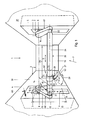
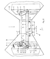
- FIGS. 1 and 2 basically show the same basic arrangement according to the invention. The differences lie in the choice and the sequence of movements of the paint application devices. The elements of the basic arrangement and their description therefore apply to both embodiments in FIGS. 1 and 2.
- the basic arrangement has a paint application machine 1, which is arranged, for example, in a spray booth 2 of a car body painting system.
- Car bodies are moved in the conveying direction F between a left side wall 30 and a right side wall 31 of the spray booth 2, in order to be covered with a layer of paint.
- a left side module 4 is arranged in the left side wall 30 and a right side module 5 is arranged in the right side wall 31.
- the side modules 4 and 5 are movement devices which are equipped with drive elements (not shown) for the paint application machine 1 and their movement elements.
- Means are assigned to each movement device, which impart different-axis movements to one or more paint application devices. These means consist of swivel and linear movement devices.
- a left lifting device 6 is assigned to the left side module 4 and a right lifting device 7 is assigned to the right side module 5.
- Each lifting device 5, 6 is provided with a swivel device 60, 61.
- the left lifting device 6 carries a left pivot shaft 8 and the right lifting device 7 a right pivot shaft 9.
- the pivot shafts 8 and 9 lie in a common horizontal axis 14. Both lifting devices 6 and 7 move the pivot shafts 8 and 9 in the direction of a vertical axis designated 10.
- a recess 3 in the side modules 4 and 5 enables the swivel shafts 8 and 9 to move vertically V.
- the vertical movement V takes place between an upper turning point 12 and a lower turning point 13. Between the points 12 and 13, the horizontal axis 14 executes a vertical useful stroke 11.
- the vertical axis 10 is fixed relative to the spray booth 1 or the conveying direction F.
- Both pivot shafts 8 and 9 are coupled to one another in such a way that they can be moved together about the horizontal axis 14 in the direction of a pivoting movement S1.
- the swiveling movement S1 takes place in the region of a swiveling angle 17.
- the drive for the swiveling movement S1 lies, not shown, in the side modules 4 and 5.
- the left swivel shaft 8 is fixedly connected to a left swivel arm 15 and the right swivel shaft 9 to a right swivel arm 16.
- the swivel arms 15 and 16 therefore carry out the same swivel movement S1 as the swivel shafts 8 and 9.
- the left side arm 15 carries a left axis 21 and the right pivot arm 16 carries an axis 22.
- Each of the axes 21 and 22 lies at a distance 18 from the axis 14 on the respective pivot arm.
- the two axes 21 and 22 therefore lie on a common pivot axis 19.
- the pivot axes 21 and 22 are connected to one another via a transverse portal 20.
- the cross portal 20 consists of a cross portal axis 24, which thus also lies on the pivot axis 19.
- the axes 21 and 22 are pivotally mounted in the respective pivot arms and are set in pivoting movement S2 about the pivot axis 19 by drive means (not shown).
- Power transmission means are provided in the swivel arms 15 and 16 and within the leg shafts 8 and 9.
- the drive itself takes place in the respective side modules 4 and 5.
- the swivel movement S2 takes place within a swivel angle 23.
- the pivoting movement S2 about its own pivot axis 19 is possible.
- 63 schematically shows a drive connection which could, for example, couple the drives of the side modules 4 and 5 to one another.
- the transverse portal axis 24 is provided with a paint application device 27 which throws paint particles against a body in the application direction A
- the paint application device 27 can be moved on the one hand in or against the conveying direction F by the combination of the movements V, S1 and S2.
- the application direction A can take place at different angles 34 with respect to a perpendicular 33 to the conveying direction F or parallel to the vertical axis 10.
- the application direction A is opposite to the conveying direction F i.e. the angle 34 is negative.
- the ink application device 27 "is such that the application direction A" points in the conveying direction F, i.e. the angle 34 "is positive.
- the paint application device 27 has a trailing distance 46 with respect to the vertical axis 10. In the dashed position, the paint application device has 27 'with respect to the vertical axis 10 a lead distance 47.
- FIG. 4 shows a car body spraying system 45 with a leading body 35 which has a body surface 39 and a trailing body 36 which has a body surface 40.
- the bodies 35 and 36 follow one another at a distance 37 in the conveying direction F.
- An order distance is denoted by 38 in which a paint applicator 27 is located opposite the surface of the car body.
- a dash-dotted line 41 is drawn along the body surfaces 39 and 40, which thus indicates the position of one or more paint applicators 27 during the spraying process. Since the paint must always be applied perpendicularly to the body surfaces 39 and 40, the angle 34 shown in FIG. 3 must always be adapted to the respective surface point.
- the ink application machine 1 is only shown schematically.
- a point 42 is drawn on the dash-dotted line 41. The same marks the position of the paint application device 27 relative to the last surface point of a rear section 48 on the body surface 39 of the lead body 35, which has to be sprayed.
- a point 43 marks the position of the paint application device 27 relative to the first surface point of a front part 59 on the body surface 40 of the trailer body 36, which has to be sprayed.
- a dotted line 44 between points 42 and 43 represents the movement sequence of the paint application device 27.
- the direction of paint application A at point 42 is practically or approximately the same as the conveying direction F. At point 43, however, the direction of paint application is opposite to the conveying direction F.
- the paint application device 27 practically changes the order direction by 180 °.
- the ink application machine 1 or the ink application device 27 Since the bodies follow one another at relatively short intervals 37 in practical operation and the throughput speeds are also relatively high, it is necessary for the ink application machine 1 or the ink application device 27 not only to be able to perform a vertical movement V and a swivel movement S2, but also additionally a swivel movement S1.
- this enables the paint application device 27 to run ahead or behind the vertical axis 10 fixed in the spray booth 1.
- a transverse displacement device 62 with a displacement ring 25 is further arranged on the transverse portal axis 24.
- the latter can carry out a horizontal transverse movement H with a horizontal stroke 26 on the transverse portal axis 24.
- the horizontal stroke 26 corresponds to the useful stroke of the machine.
- the sliding ring 25 is provided with a pivot mechanism 28.
- the same moves about a pivot axis 32.
- the pivot axis 32 runs, for example, parallel to the conveying direction F.
- the pivot mechanism 28 carries two spray guns 52, 53 which perform a pivoting movement S3 about the pivot axis 32.
- the swiveling movement S3 takes place within a swiveling angle 29.
- corner parts 49 and 50 (FIG. 5) of a car body roof 51 can be provided with paint as required.
- a plurality of paint application devices 27 which are connected to one another are further provided, in the example shown being electrostatic spray bells 54, 55, 56.
- the spray bells 54, 55, 56 move in parallel with one another in an oscillating movement 0.
- the spray bells 54, 55, 56 are arranged at adjustable distances 58.59 from one another.
- the amplitude of the oscillation movement 0 is such that the paint application spray mists of the adjacent spray bells complement each other and result in a color layer on the body surface which is balanced in terms of thickness and area uniformity.
- the spray bells 54, 55 and 56 also perform the pivoting movement S2 about the pivot axis 19.
- one or more paint application devices can be attached to the cross portal.
- the ink application machine is preferably constructed modularly, e.g. side modules and connecting modules arranged transversely to it (cross portal).
- the coupling takes place by means of swivel arms between the side module and the cross portal.
- the movements required for an application (number of axes) and movement lengths (useful strokes and swivel angles) are specifically selected according to the given needs.
- the drives provided for the axis movement are stationary so that the risk of cable breaks can be avoided.
- the special flexibility of the paint application machine 1 allows it to be used inside or outside a pointed booth 2.
- the side modules 4, 5 are arranged outside the booth.
- the swivel arms 15, 16 and the transverse module 20 are located within the cabin 2.
- a recess 3 in the cabin side walls in the direction of the linear movement V of the side modules enables the connection between the side and transverse modules by means of the swivel arms.
- the entire paint application machine is located within the Cabin set up.
- the paint application machine according to the invention is particularly suitable for painting motor vehicle bodies.
Landscapes
- Engineering & Computer Science (AREA)
- Robotics (AREA)
- Spray Control Apparatus (AREA)
Abstract
Description
- Die Erfindung betrifft eine Farbauftragsmaschine zum Lackieren von Kraftfahrzeugkarossen mit mindestens einer Bewegungseinrichtung, die ein oder mehrere mit ihr in dynamischer Verbindung stehende Farbauftragsgeräte aufweist, die von der Bewegungseinrichtung in zwei quer zur Förderrichtung der Karossen liegenden Raumachse linear bewegt und um mindestens eine Raumachse geschwenkt werden.
- Farbauftragsmaschinen sind bekannt für das Lackieren von Autokarossen, bei welchen die Farbauftragsgeräte durch seitlich oder über der Karosse angeordnete Einrichtungen entlang der Karossenoberfläche quer zur Förderrichtung gefahren werden.
- Es ist beim Farbauftragen auf Autokarossen ein bekanntes Merkmal, dass der Abstand des Farbauftragsgerätes bzw. der Farbspritzabstand jeweils über die ganze Oberfläche immer gleich und die Auftragsrichtung jeweils immer senkrecht zur Oberfläche sein sollte.
- Es ist eine Konturmaschine nach Europäische Patentanmeldung (Veröffentlichungs-No. 0 338 334 A) bekannt, bei welcher Farbauftragsgeräte über mehrere Motoren linear längs zwei Raumachsen und um zwei Raumachsen drehbar angetrieben sind. Da diese Anordnung nur relativ langsame Bewegungen ausführen kann, insbesondere in X und Z-Achse, eignet sie sich nicht für Front- und Heckpartien von Fahrzeugen. In bekannten Durchlaufanlagen folgen die einzelnen Karossen in kurzen Abständen. Farbauftragsgeräte, die nur in X-und Z-Achse bewegt werden, wie z. B. mit der oben beschriebenen bekannten Konturmaschine, sind zu langsam, um während der verbleibenden Zeit in die Zwischenräume der Karossen ein- und auszufahren ohne Kollisionen mit den Karossen.
- Auch eine weitere bekannte Farbauftragsmaschine löst dieses Problem nicht, obwohl diese sehr rasche Verfahrbewegung der Farbauftragsgeräte in X und Z-Achse ermöglicht. Diese bekannte Anordnung verwendet ein Jochportal, das in seitlichen Gestellen in Vertikalrichtung (Z-Achse) verschiebbar ist. Das Jochportal ist um die X-Achse schwenkbar und trägt eine Verschiebeeinheit, die in die X-Achse verschiebbar ist. Die Verschiebeeinheit ist mit Farbauftragsgeräten bestückt, die ihrerseits um die Y-Achse schwenkbar sind. Auch mit dieser Einrichtung können Front- und Heckpartien nicht einwandfrei lackiert werden.
- Aufgabe der Erfindung ist es, auch höhenmässig lange Front- und Heckpartien von Karossen im Durchlaufverfahren zu lackieren.
- Die gestellte Aufgabe ist gemäss der Neuerung dadurch gelöst, dass der Bewegungseinrichtung Mittel zugeordnet sind, die ermöglichen, die Farbauftragsgeräte in einer dritten Raumachse, die längs der Fördereinrichtung der zu lackierenden Karosse liegt, zu bewegen.
- Der Vorteil der Erfindung liegt darin, dass durch das Bewegen der Farbauftragsgeräte in der dritten Achse (Y-Achse) die Farbauftragsgeräte in einem gewissen Arbeitsbereich mit den Karossen in Förderrichtung mitlaufen können, auch wenn die Bewegungseinrichtung gegenüber der Förderung stillsteht.
- Gemäss einer bevorzugten Ausführungsform ist es deshalb vorteilhaft, wenn die der Bewegungseinrichtung zugeordneten Mittel aus mindestens einer Linearbewegungssvorrichtung und mindestens einer Schwenkvorrichtung bestehen, die in ihren Bewegungen kombiniert sind zur Bewegung von mindestens einem Farbauftragsgerät in einer längs der Förderrichtung liegenden Raumachse. Da die Autokarossen praktisch nur gebogene Oberflächen aufweisen, wird es notwendig, den Farbauftragsgeräten mehrdimensionale Bewegungen zu erteilen. Eine Lösung dieser Aufgabe bringt eine weitere Ausführungsform, wenn die Linearbewegungsvorrichtung aus mindestens einer Hubeinrichtung und mindestens einer in derselben drehbar gelagerten Schwenkwelle besteht, die Schwenkvorrichtung aus mindestens einem mit der Schwenkwelle verbundenen Schwenkarm sowie einem in einem Abstand von der Schwenkwelle angeordneten Querportal besteht und das Querportal eine Querschiebevorrichtung trägt, dass ferner das Querportal schwenkbar im Schwenkarm gelagert ist, und die Querverschiebevorrichtung einen Schwenkmechanismus trägt, an welchem mindestens ein Farbauftragsgerät angelenkt ist.
- Die Kombination von fünf Bewegungen ergibt für die Farbauftragsgeräte ein entsprechendes maximales dreidimensionales Wirkungsfeld.
- Der modulare und flexible Aufbau sowie die stationär angeordneten Antriebe ermöglichen den Einsatz der erfindungsgemässen Farbauftragsmaschine innerhalb oder ausserhalb einer Spritzkabine.
- Nachfolgend sind beispielsweise Ausführungen der erfindungsgemässen Farbauftragsmaschine unter Bezugnahme auf die beiliegende Figur näher erläutert.
- Es zeigt:
- Fig. 1 eine perspektivische Darstellung einer ersten Ausführungsform mit zur Fahrtrichtung quer verschiebbaren und schwenkbaren Farbauftragsgeräten.
- Fig. 2 eine perspektivische Darstellung einer zweiten Ausführungsform mit quer zur Fahrtrichtung oszillierenden Farbauftragsgeräten.
- Fig. 3 eine schematische Darstellung der erfindungsgemässen Anordnung einer Farbauftragsmaschine.
- Fig. 4 eine schematische Darstellung einer erfindungsgemässen Farbauftragsmaschine in einer Autokarossenspritzanlage.
- Fig. 5 Querschnitt durch eine Spritzkabine einer in Fig. 1 dargestellten Ausführungsform.
- Die in den Fig. 1 und 2 dargestellten Ausführungsformen zeigen grundsätzlich die gleiche erfindungsgemässe Grundanordnung. Die Unterschiede liegen in der Wahl und im Bewegungsablauf der Farbauftragsgeräte. Die Elemente der Grundanordnung und deren Beschreibung gelten deshalb für beide Ausführungsformen in Fig. 1 und 2.
- Die Grundanordnung weist eine Farbauftragsmaschine 1 auf, die beispielsweise in einer Spritzkabine 2 einer Autokarossenlackieranlage angordnet ist. Zwischen einer linken Seitenwand 30 und einer rechten Seitenwand 31 der Spritzkabine 2 werden auf nicht dargestellte Weise Autokarossen in Förderrichtung F bewegt, um mit einer Farbschicht bedeckt zu werden. In der linken Seitenwand 30 ist ein linkes Seitenmodul 4 und in der rechten Seitenwand 31 ein rechtes Seitenmodul 5 angeordnet. Die Seitenmodule 4 und 5 sind Bewegungseinrichtungen, die mit nicht dargestellten Antriebsorganen für die Farbauftragsmaschine 1 und deren Bewegungsorgane bestückt sind. Jeder Bewegungseinrichtung sind Mittel zugeordnet, die einem oder mehreren Farbauftragsgeräten verschiedenachsige Bewegungen erteilen. Diese Mittel bestehen aus Schwenk- und Linearbewegungsvorrichtungen. So ist unter anderem dem linken Seitenmodul 4 eine linke Hubeinrichtung 6 und dem rechten Seitenmodul 5 eine rechte Hubeinrichtung 7 zugeordnet. Jede Hubeinrichtung 5, 6 ist mit einer Schwenkvorrichtung 60, 61 versehen. Die linke Hubeinrichtung 6 trägt eine linke Schwenkwelle 8 und die rechte Hubeinrichtung 7 eine rechte Schwenkwelle 9. Die Schwenkwellen 8 und 9 liegen in einer gemeinsamen Horizontalachse 14. Beide Hubeinrichtungen 6 und 7 bewegen die Schwenkwellen 8 und 9 in Richtung einer mit 10 bezeichneten Vertikalachse. Eine Aussparung 3 in den Seitenmodulen 4 und 5 ermöglicht den Schwenkwellen 8 und 9 eine Vertikalbewegung V. Die Vertikalbewegung V erfolgt zwischen einem oberen Umkehrpunkt 12 und einem unteren Umkehrpunkt 13. Zwischen den Punkten 12 und 13 führt die Horizontalachse 14 einen vertikalen Nutzhub 11 aus. Die Vertikalachse 10 ist gegenüber der Spritzkabine 1 bzw. der Förderrichtung F feststehend.
- Beide Schwenkwellen 8 und 9 sind derart miteinander gekoppelt, dass sie gemeinsam um die Horizontalachse 14 bewegbar sind in Richtung einer Schwenkbewegung S1. Die Schwenkbewegung S1 erfolgt im Bereiche eines Schwenkwinkels 17. Der Antrieb für die Schwenkbewegung S1 liegt, nicht dargestellt, in den Seitenmodulen 4 und 5.
- Die linke Schwenkwelle 8 ist mit einem linken Schwenkarm 15 und die rechte Schwenkwelle 9 mit einem rechten Schwenkarm 16 fest verbunden. Die Schwenkarme 15 und 16 führen deshalb die gleiche Schwenkbewegung S1 aus wie die Schwenkwellen 8 und 9.
- Der linke Seitenarm 15 trägt eine linke Achse 21 und der rechte Schwenkarm 16 eine Achse 22. Jede der Achsen 21 und 22 liegt in einem Abstand 18 von der Achse 14 am jeweiligen Schwenkarm. Die beiden Achsen 21 und 22 liegen deshalb auf einer gemeinsamen Schwenkachse 19. Die Schwenkachsen 21 und 22 sind über ein Querportal 20 miteinander verbunden. Das Querportal 20 besteht aus einer Querportalachse 24 die somit ebenfalls auf der Schwenkachse 19 liegt.
- Die Achsen 21 und 22 sind in den jeweiligen Schwenkarmen schwenkbar gelagert und werden von nicht näher dargestellten Antriebsmitteln in Schwenkbewegung S2 um die Schwenkachse 19 versetzt. Nicht dargestellte Kraftübertragungsmittel sind in den Schwenkarmen 15 und 16 sowie innerhalb der Schenkwellen 8 und 9 vorgesehen. Der Antrieb selbst erfolgt in den jeweiligen Seitenmodulen 4 und 5. Die Schwenkbewegung S2 erfolt innerhalb eines Schwenkwinkels 23. Durch Verdrehung der Schwenkwellen 8 und 9 führt das Querportal 20 bzw. die Querportalwelle 24 die Schwenkbewegung S1 im Abstand 18 (=Schwenkradius) um die Horizontalachse 14 aus. Gleichzeitig ist die Schwenkbewegung S2 um die eigene schwenkachse 19 möglich.
- Mit 63 ist schematisch eine Antriebsverbindung dargestellt, die beispielsweise die Antriebe der Seitenmodule 4 und 5 miteinander koppeln könnte.
- In der Fig. 3 sind schematisch die Bewegungmöglichkeiten V, S1 und S2 dargestellt wie die Grundanordnung der erfindungsgemässen Farbauftragmaschine dies ermöglicht. Wird beispielsweise die Querportalachse 24 mit einem Farbauftraggerät 27 versehen, das in Auftragsrichtung A Farbpartikel gegen eine Karosse schleudert, so kann das Farbauftraggerät 27 durch die Kombination der Bewegungen V, S1 und S2 einerseits in oder gegen die Förderrichtung F bewegt werden. Andererseits kann die Auftragsrichtung A gegenüber einer Senkrechten 33 zur Förderrichtung F bzw. Parallele zur Vertikalachse 10 in verschiedenen Winkeln 34 erfolgen. Im dargestellten Beispiel ist die Auftragsrichtung A entgegen der Förderrichtung F d.h. der Winkel 34 ist negativ. In der gestrichelt dargestellten Stellung im unteren Umkehrpunkt 13 steht beispielsweise das Farbauftragsgerät 27" derart, dass die Auftragsrichtung A" in Förderrichtung F zeigt, d.h. der Winkel 34" ist positiv.
- Das Farbauftragsgerät 27 hat gegenüber der Vertikalachse 10 einen Nachlaufabstand 46. In der gestrichelten Stellung hat das Farbauftragsgerät 27' gegenüber der Vertikalachse 10 einen Vorlaufabstand 47.
- In der Fig. 4 ist eine Autokarossenspritzanlage 45 dargestellt mit einer Vorlaufkarosse 35 die eine Karossenoberfläche 39 aufweist, und eine Nachlaufkarosse 36 die eine Karossenoberfläche 40 aufweist. Die Karossen 35 und 36 folgen einander in einem Abstand 37 in Förderrichtung F. Mit 38 ist ein Auftragsabstand bezeichnet in welchem ein Farbauftragsgerät 27 gegenüber der Autokarossenoberfläche steht.
- Entlang der Karossenoberflächen 39 und 40 ist eine strichpunktierte Linie 41 gezeichnet, die damit die Stellung eines oder mehrerer Farbauftragsgeräte 27 während dem Spritzvorgang kennzeichnet. Da die Farbauftragung immer senkrecht auf die Karossenoberfäche 39 und 40 zu erfolgen hat, muss der in Fig. 3 dargestellte Winkel 34 immer dem jeweiligen Oberflächenpunkt angepasst werden.
- In der Fig. 4 ist die Farbauftragsmaschine 1 nur schematisch dargestellt.
- Auf der strichpunktierten Linie 41 ist ein Punkt 42 eingezeichnet. Derselbe markiert die Stellung des Farbauftragsgerätes 27 gegenüber dem letzten Oberflächenpunkt einer Heckpartie 48 auf der Karossenoberfläche 39 der Vorlaufkarosse 35, die gespritzt werden muss. Ein Punkt 43 markiert die Stellung des Farbauftragsgerätes 27 gegenüber dem ersten Oberflächenpunkt einer Frontpartie 59 auf der Karossenoberfläche 40 der Nachlaufkarosse 36, die gespritzt werden muss. Eine punktiert dargestellte Linie 44 zwischen den Punkten 42 und 43 stellt den Bewegungsablauf des Farbauftragsgerätes 27 dar. Die Farbauftragsrichtung A im Punkt 42 ist praktisch bzw. annähernd gleich der Förderrichtung F. Im Punkt 43 hingegen ist die Farbauftragsrichtung entgegengesetzt der Förderrichtung F. Das Farbauftragsgerät 27 ändert praktisch die Auftragsrichtung um 180 ° . Da die Karossen im praktischen Betrieb einander in relativ kurzen Abständen 37 folgen und die Durchlaufgeschwindigkeiten ebenso relativ hoch sind, bedingt es, dass die Farbauftragsmaschine 1 bzw. das Farbauftragsgerät 27 nicht nur eine Vertikalbewegung V und eine Schwenkbewegung S2 ausführen kann, sondern auch zusätzlich eine Schwenkbewegung S1.
- Diese ermöglicht erfindungsgemäss das Vor- bzw. Nachlaufen des Farbauftragsgerätes 27 gegenüber der in der Spritzkabine 1 feststehenden Vertikalachse 10.
- In der Fig. 1 ist im weiteren auf der Querportalachse 24 eine Querverschiebevorrichtung 62 mit einem Verschiebering 25 angeordnet. Der letztere kann auf der Querportalachse 24 eine Horizontalquerbewegung H ausführen mit einem Horizontalhub 26. Der Horizontalhub 26 entspricht dem Nutzhub der Maschine.
- Der Verschiebering 25 ist mit einem Schwenkmechanismus 28 versehen. Derselbe bewegt sich um eine Schwenkachse 32. Die Schwenkachse 32 verläuft beispielsweise parallel zur Förderrichtung F. Der Schwenkmechanismus 28 trägt im vorliegenden Beispiel zwei Spritzpistolen 52,53 die um die Schwenkachse 32 eine Schwenkbewegung S3 ausführen. Die Schwenkbewegung S3 erfolgt innerhalb eines Schwenkwinkels 29. Damit können Eckpartien 49 und 50 (Fig. 5) eines Autokarossendaches 51 anforderungsgemäss mit Farbauftrag versehen werden.
- In der Fig. 2 sind im weiteren mehrere miteinander in Querverbindung stehende Farbauftragsgeräte 27 vorgesehen, wobei es sich im dargestellten Beispiel um elektrostatische Sprühglocken 54,55,56 handelt. Die Sprühglocken 54,55,56 bewegen sich parallel miteinander in einer Oszillationsbewegung 0. Die Sprühglocken 54,55,56 sind in einstellbaren Abständen 58,59 voneinander angeordnet. Die Amplitude der Oszillationsbewegung 0 ist derart, dass sich jeweils die Farbauftragssprühnebel der benachbarten Sprühglocken ergänzen und eine in Dicke und Flächengleichheit ausgeglichene Farbschicht auf der Karossenfläche ergeben.
- Die Sprühglocken 54,55 und 56 führen ebenfalls die Schwenkbewegung S2 um die Schwenkachse 19 aus.
- In den dargestellten Ausführungsformen der erfindungsgemässen Farbauftragsmaschine können am Querportal ein oder mehrere Farbauftragsgeräte angebracht sein.
- Die Farbauftragsmaschine wird vorzugsweise modular aufgebaut, z.B Seitenmodule und quer dazu angeordnete Verbindungsmodule (Querportal). Die Zusammenkoppelung erfolgt mittels Schwenkarmen zwischen Seitenmodul und Querportal.
- Die für einen Anwendungsfall notwendigen Bewegungen (Anzahl Achsen) und Bewegungslängen (Nutzhübe und Schwenkwinkel) werden spezifisch nach den gegebenen Bedürfnissen ausgewählt.
- Die für die Achsenbewegung vorgesehenen Antriebe sind stationär angeordnet, so dass die Gefahr von Kabelbrüchen vermieden werden kann.
- Die besondere Flexibilität der Farbauftragsmaschine 1 erlaubt deren Einsatz inerhalb oder ausserhalb einer Spitzkabine 2. Bei der Version Kabinenaussenliegend, wie es die Fig. 1 und 2 zeigen, werden die Seitenmodule 4,5 ausserhalb der Kabine angeordnet. Die Schwenkarme 15,16 und das Quermodul 20 befinden sich innerhalb der Kabine 2. Eine Aussparung 3 in den Kabinen-Seitenwänden in Richtung der Linearbewegung V der Seitenmodule ermöglicht die Verbindung zwischen Seiten- und Quermodul mittels der Schwenkarme.
- Bei der kabineninnenliegenden Version wird die gesamte Farbauftragsmaschine innerhalb der Kabine aufgestellt.
- Die Farbauftragsmaschine nach der Erfindung eignet sich insbesondere zur Lackierung von Kraftfahrzeugkarossen.
Claims (7)
Applications Claiming Priority (2)
| Application Number | Priority Date | Filing Date | Title |
|---|---|---|---|
| CH3038/90 | 1990-09-20 | ||
| CH303890 | 1990-09-20 |
Publications (2)
| Publication Number | Publication Date |
|---|---|
| EP0476561A2 true EP0476561A2 (de) | 1992-03-25 |
| EP0476561A3 EP0476561A3 (en) | 1992-05-13 |
Family
ID=4247227
Family Applications (1)
| Application Number | Title | Priority Date | Filing Date |
|---|---|---|---|
| EP19910115675 Ceased EP0476561A3 (en) | 1990-09-20 | 1991-09-16 | Painting installation |
Country Status (2)
| Country | Link |
|---|---|
| US (1) | US5213620A (de) |
| EP (1) | EP0476561A3 (de) |
Cited By (1)
| Publication number | Priority date | Publication date | Assignee | Title |
|---|---|---|---|---|
| WO1992014553A1 (fr) * | 1991-02-15 | 1992-09-03 | Seitz, Reiner | Machine pour revetir des carrosseries automobiles |
Families Citing this family (5)
| Publication number | Priority date | Publication date | Assignee | Title |
|---|---|---|---|---|
| FR2703265B1 (fr) * | 1993-04-01 | 1995-06-23 | Sames Sa | Machine de projection de produit de revetement par voie electrostatique. |
| RU2104807C1 (ru) | 1993-07-19 | 1998-02-20 | Эйбиби Тралфа Робот АС | Установка робота для окрашивания объектов |
| DE202004021737U1 (de) * | 2003-07-18 | 2010-08-26 | Abb As | Farbauftragssystem |
| US10864541B2 (en) * | 2018-01-30 | 2020-12-15 | Ford Motor Company | Ultrasonic atomizer with quick-connect mechanism |
| CN112170076A (zh) * | 2020-09-10 | 2021-01-05 | 肖冬梅 | 一种门窗生产用门板喷漆机 |
Family Cites Families (7)
| Publication number | Priority date | Publication date | Assignee | Title |
|---|---|---|---|---|
| BE759240A (fr) * | 1970-02-14 | 1971-04-30 | Ransburg Gmbh | Procede et appareil d'enduisage de surfaces irregulieres par pulverisation |
| GB2087269B (en) * | 1980-10-23 | 1984-05-10 | Binks Bullows Ltd | Paint spraying apparatus for moving vehicle bodies |
| GB2190312B (en) * | 1986-04-01 | 1990-12-19 | Honda Motor Co Ltd | Method and apparatus for painting object |
| US4762013A (en) * | 1986-08-06 | 1988-08-09 | The Devilbiss Company | Reciprocating device for spray coating |
| DE3813058A1 (de) * | 1988-04-19 | 1989-11-09 | Devilbiss Gmbh | Frei programmierbare konturmaschine |
| JPH026868A (ja) * | 1988-06-25 | 1990-01-11 | Taikisha Ltd | 塗装ブースにおける塗装装置設置方法と塗装ブースの一部を構成する塗装機操作ユニット |
| DE3911454A1 (de) * | 1989-04-07 | 1990-10-11 | Behr Industrieanlagen | Dachmaschine |
-
1991
- 1991-09-16 EP EP19910115675 patent/EP0476561A3/de not_active Ceased
- 1991-09-19 US US07/762,757 patent/US5213620A/en not_active Expired - Fee Related
Cited By (1)
| Publication number | Priority date | Publication date | Assignee | Title |
|---|---|---|---|---|
| WO1992014553A1 (fr) * | 1991-02-15 | 1992-09-03 | Seitz, Reiner | Machine pour revetir des carrosseries automobiles |
Also Published As
| Publication number | Publication date |
|---|---|
| US5213620A (en) | 1993-05-25 |
| EP0476561A3 (en) | 1992-05-13 |
Similar Documents
| Publication | Publication Date | Title |
|---|---|---|
| DE102004033640B4 (de) | Farbauftragssystem | |
| EP0338334B1 (de) | Frei programmierbare Konturmaschine | |
| DE10149424B4 (de) | Maschine für das automatische Anstreichen von Platten oder anderen Gegenständen | |
| DE3626610A1 (de) | Portalsystem | |
| DE60123924T2 (de) | Spritzvorrichtung, insbesondere für eine Lackierkabine für Fahrzeugkarosserien | |
| DE102005033972A1 (de) | Beschichtungsverfahren und zugehörige Beschichtungseinrichtung | |
| DE69011630T2 (de) | Automatische Farbspritzmaschine. | |
| DE10359280A1 (de) | Sprühbeschichtungsvorrichtung | |
| EP0392267B1 (de) | Maschine zum Beschichten von Automobilkarosserien | |
| DE69321617T2 (de) | In eine sprühbeschichtungskabine installierte robotereinrichtung | |
| DE1580769B2 (de) | Anordnung zum Waschen von Fahrzeugen in Fahrzeugwaschanlagen | |
| EP1419824B1 (de) | Vorrichtung zum Beschichten eines Werkstücks mit Pulver | |
| DE69005404T2 (de) | Farbsprühsystem. | |
| EP0536459B1 (de) | Vorrichtung zum automatischen Sprühbeschichten von Gegenständen | |
| DE102004040161B4 (de) | Vorrichtung zum Beschichten von Gegenständen | |
| DE19524748C2 (de) | Waschvorrichtung für eine Fahrzeug-Waschstraße | |
| DE2516609B2 (de) | Waschanlage zum Reinigen von Fahrzeugkarosserien | |
| DE19643138C2 (de) | Fahrzeug zum Befahren beliebig geneigter Flächen aus ferromagnetischem Material | |
| DE69004502T2 (de) | Fahrzeugwaschanlage mit beinahe elliptischen zylindrischen Bürsten die auf in Längsrichtung waagerechten Achsen drehen. | |
| DE10158129A1 (de) | Entstaubungsanlage für Fahrzeugkarossen | |
| DE10006865B4 (de) | Verfahren zum Lackieren von Fahrzeugkarosserien | |
| DE8805181U1 (de) | Frei programmierbare Konturmaschine | |
| DE102004064236B3 (de) | Roboter | |
| DE102024117259A1 (de) | Roboter mit versetzten Achsenebenen | |
| DE3234818C2 (de) |
Legal Events
| Date | Code | Title | Description |
|---|---|---|---|
| PUAI | Public reference made under article 153(3) epc to a published international application that has entered the european phase |
Free format text: ORIGINAL CODE: 0009012 |
|
| PUAL | Search report despatched |
Free format text: ORIGINAL CODE: 0009013 |
|
| AK | Designated contracting states |
Kind code of ref document: A2 Designated state(s): BE CH DE ES FR GB IT LI SE |
|
| AK | Designated contracting states |
Kind code of ref document: A3 Designated state(s): BE CH DE ES FR GB IT LI SE |
|
| 17P | Request for examination filed |
Effective date: 19921031 |
|
| 17Q | First examination report despatched |
Effective date: 19940214 |
|
| STAA | Information on the status of an ep patent application or granted ep patent |
Free format text: STATUS: THE APPLICATION HAS BEEN REFUSED |
|
| 18R | Application refused |
Effective date: 19960202 |