EP0476626B1 - Bogenanleger - Google Patents
BogenanlegerInfo
- Publication number
- EP0476626B1 EP0476626B1 EP91115859A EP91115859A EP0476626B1 EP 0476626 B1 EP0476626 B1 EP 0476626B1 EP 91115859 A EP91115859 A EP 91115859A EP 91115859 A EP91115859 A EP 91115859A EP 0476626 B1 EP0476626 B1 EP 0476626B1
- Authority
- EP
- European Patent Office
- Prior art keywords
- suction
- sheet
- sheet feeder
- suction box
- fixed gate
- Prior art date
- Legal status (The legal status is an assumption and is not a legal conclusion. Google has not performed a legal analysis and makes no representation as to the accuracy of the status listed.)
- Expired - Lifetime
Links
- 230000007246 mechanism Effects 0.000 claims description 14
- 238000004891 communication Methods 0.000 claims description 8
- 238000005192 partition Methods 0.000 claims description 8
- 238000010276 construction Methods 0.000 description 2
- 239000011096 corrugated fiberboard Substances 0.000 description 2
- 230000003292 diminished effect Effects 0.000 description 2
- 239000012634 fragment Substances 0.000 description 1
- 238000004519 manufacturing process Methods 0.000 description 1
Images


Classifications
-
- B—PERFORMING OPERATIONS; TRANSPORTING
- B65—CONVEYING; PACKING; STORING; HANDLING THIN OR FILAMENTARY MATERIAL
- B65H—HANDLING THIN OR FILAMENTARY MATERIAL, e.g. SHEETS, WEBS, CABLES
- B65H3/00—Separating articles from piles
- B65H3/24—Separating articles from piles by pushers engaging the edges of the articles
-
- B—PERFORMING OPERATIONS; TRANSPORTING
- B65—CONVEYING; PACKING; STORING; HANDLING THIN OR FILAMENTARY MATERIAL
- B65H—HANDLING THIN OR FILAMENTARY MATERIAL, e.g. SHEETS, WEBS, CABLES
- B65H3/00—Separating articles from piles
- B65H3/08—Separating articles from piles using pneumatic force
- B65H3/12—Suction bands, belts, or tables moving relatively to the pile
- B65H3/124—Suction bands or belts
- B65H3/126—Suction bands or belts separating from the bottom of pile
-
- B—PERFORMING OPERATIONS; TRANSPORTING
- B65—CONVEYING; PACKING; STORING; HANDLING THIN OR FILAMENTARY MATERIAL
- B65H—HANDLING THIN OR FILAMENTARY MATERIAL, e.g. SHEETS, WEBS, CABLES
- B65H2301/00—Handling processes for sheets or webs
- B65H2301/40—Type of handling process
- B65H2301/42—Piling, depiling, handling piles
- B65H2301/423—Depiling; Separating articles from a pile
- B65H2301/4232—Depiling; Separating articles from a pile of horizontal or inclined articles, i.e. wherein articles support fully or in part the mass of other articles in the piles
- B65H2301/42322—Depiling; Separating articles from a pile of horizontal or inclined articles, i.e. wherein articles support fully or in part the mass of other articles in the piles from bottom of the pile
Definitions
- the present invention relates to a sheet feeder for kicking out stacked-up thick sheets one by one from the lowermost position.
- a printer slotter is used for printing on corrugated fiberboards and die-cutting and creasing the boards.
- GB-A-2 013 630 A discloses a blank feeding apparatus for feeding blanks one after another from a stack of blanks to processing rolls.
- An endless chain conveyor passes around a pair of sprocket wheels located under a table. A plurality of such sprocket wheels are arranged next to each other. The sprocket wheels are driven by a DC servomotor through a common driving shaft.
- Each conveyor chain is provided with two kickers for pushing the rear end of each blank, the kickers being mounted on the conveyor chain at a suitable distance from each other.
- Suction boxes are provided under the table to provide suction forces to each blank from underneath while it is conveyed.
- Guide bars are arranged between processing rolls and below a front guide means.
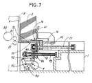
- Figs. 6 and 7 show a sheet feeder for use in feeding corrugated fiberboards, i.e., sheets, to the printer slotter.
- the sheet feeder includes a fixed gate 4 disposed at the front end of a base 1, and a movable guide plate 41 positionable in place and movable toward and away from the fixed gate. Thick sheets S stacked up between the fixed gate 4 and the movable guide plate 41 are kicked out toward the printer slotter one by one from the lowermost position of the stack by a kicker 10 and a suction device (not shown) on the base 1.
- the kicker 10 has a kicker plate 14 slidably provided on the base 1 and reciprocatingly movable by a crank 9.
- a kicker plate 14 slidably provided on the base 1 and reciprocatingly movable by a crank 9.
- an engaging portion 15 of the plate 14 engages the rear end of the lowermost sheet to kick out the sheet.
- the suction device applies suction at least locally on the lower surface of the lowermost sheet so that the sheet can be smoothly kicked out even if warped.
- the kicker plate 14 and the movable guide plate 41 are coupled to positioning mechanisms 7, 70, respectively, for positioning these plates in place on the base 1 with respect to the direction of feed of the sheet in accordance with the width of the sheet.
- the positioning mechanism 70 for the movable guide plate 41 comprises a pair of parallel screw rods 43, 43 arranged on opposite sides of the base 1 and coupled to drive means (not shown).
- the screw rod 43 extends through, and is in screw-thread engagement with, a leg 42 projecting from each end of the movable guide plate 41.
- the movable guide plate 41 can be brought to the desired position by the thrust of screw.
- the positioning mechanism 7 for the kicker plate 14 utilizes screw thrust, whereas since the kicker plate 14 as positioned in place needs to move reciprocatingly for kicking out sheets, the entire positioning mechanism 7 is reciprocatingly movable with the kicker plate 14.
- Screw rods 17, 17 are slidably and rotatably arranged in parallel to the screw rods 43, 43 inwardly thereof. The screw rod 17 extends through, and is in screw-thread engagement with, a leg 16 projecting from the kicker plate 14.
- a gear 18 is mounted on a front portion of the screw rod 17.
- a spline shaft 95 disposed below the screw rod 17 slidably carries thereon a drive gear 94 meshing with the gear 18 on the screw rod 17.
- a support plate 93 is rotatably fitted around the boss of the drive gear 94 and is movable with the drive gear 94 axially of the spline shaft 95.
- the support plate 93 has an upper end supporting the front end of the screw rod 17.
- the crank 9 for reciprocatingly driving the kicker plate 14 is connected to a lever 91 by a link 90.
- the lever 91 has a free end which is connected to the support plate 93 by a link 92.
- the kicker plate 14 is reciprocatingly moved relative to the base 1 to kick out the sheets S one by one by the rotation of the crank 9 which is transmitted through the link 90, lever 91, link 92, support plate 93, screw rod 17 and leg 16.
- the spline shaft 95 when rotated, causes the drive gear 94 and the gear 18 to rotate the screw rod 17, advancing or retracting the leg 16, i.e., the kicker plate 14, whereby the kicking start position of the kicker plate 14 can be adjusted in accordance with the size of the sheet S.
- the amount of kicking-out of the sheet S by the kicker plate 14 corresponds to the distance from the fixed gate 4 to feed rollers 81, 81 of the printer slotter.
- the sheet S is transported toward a plate cylinder 82 by the rotation of the feed rollers 81, 81 for printing.
- the movable guide plate 41 must be held in a position after the position has been determined with respect to the feed direction, and the kicker plate 14 needs to be reciprocatingly movable from a position which has been determined with respect to the feed direction. It is therefore impossible to use a single system for driving both the positioning mechanism 70 for the movable guide plate 41 and the positioning mechanism 7 for the kicker plate 14. Accordingly, the conventional feeder has the problem of being complex in the construction of the drive systems used.
- the sheet S is delivered to the rollers 81, 81 at the moment when the speed of movement of the kicker plate 14 is greatest.
- about 1/4 of the rotation is then effectively utilized for feeding the sheet S, hence a low efficiency.
- the actual stroke length of the kicker plate 14 needed is about twice the distance from the kicking-out start position to the nip of rollers 81, 81. This results in the drawback that the lever 91 must be made swingingly movable over a large distance.
- the conventional feeder has another drawback.
- the arrangement wherein the support plate 93, the drive gear 94 and the screw rod 17 are moved with the kicker plate 14 requires a large means (not shown) for rotating the crank 9, consequently producing increased vibration during the reciprocating movement of the kicker plate 14.
- the present invention which has been accomplished in view of the above situation, provides a sheet feeder which is adapted to kick out sheets by belts having kicker members and movable in revolution in a fixed position instead of the reciprocatingly movable kicker plate so that the sheet can be kicked out with a small torque and with diminished vibration, the sheet feeder having a simplified mechanism for positioning the kicker members and a movable guide plate in place with respect to the direction of feed of the sheet.
- the present invention provides a sheet feeder being adapted to kick out sheets stacked up between a fixed gate and a movable guide plate one by one from the lowermost position by a suction means and a kicker, the sheet feeder comprising : the fixed gate provided on the base and approximately orthogonal to the direction of feed of sheets; the movable guide plate provided on the base in parallel to the fixed gate movably toward and away from the fixed gate and positionable in place; a plurality of guide members arranged side by side above the base and orthogonal to the fixed gate; a kicker member for engaging one end of the sheet; a plurality of belts provided on a surface thereof with said kicker member; a drive means for driving the belts in revolution; and a positioning mechanism; the sheet feeder being characterized by a slide member integral with the movable guide plate and disposed over the guide members, thereacross movable toward and away from the fixed gate; a plurality of belt supports arranged between the guide members, attached to the slide member and communicating with the suction means; a
- the sheet feeder having the above structure provides a suction force uniformly acting on the entire surface of the sheet, whereby the sheet is brought into intimate contact with the guide members when the kicker members come into contact with the rear end of the sheet for delivery. Even if the sheet is warped, it can be slidingly moved on the guide members in intimate contact therewith. This ensures reliable and stable delivery of the sheet to the feed rollers.
- the suction force can be easily adjusted by opening or shutting the apertures by means of the respective closures.
- Such a width- adjustable structure of the sheet feeder provides for an appropriate operation of the machine.
- the sheet When an additional suction box opened at its upper side is provided as projected downward from the guide members, the sheet can be advanced while being held in intimate contact with the guide members by suction applied at least locally on the lower surface of the sheet through the suction box. The sheet can then be kicked out reliably even if warped.
- the additional suction box may be in communication with the belt supports or independent of the belt supports.
- FIG. 1 shows a sheet feeder embodying the present invention as it is seen from one side thereof close to a printer slotter having feed rollers 81, 81 and a plate cylinder 82.
- an additional suction box 12 is provided in communication with belt supports 22.
- front refers to the direction of feed of sheets by the feeder, i.e., the direction toward the feed rollers 81, 81.
- the sheet feeder has the above-mentioned suction box 12 opened at its upper side and mounted on a base 1.
- the suction box 12 is equidistantly divided by partitions 19 in a direction orthogonal to the feed rollers 81.
- a guide member 11 in the form of a rod of square cross section is mounted on the upper end of each partition 19.
- a suction duct 28 parallel to the feed rollers 81 and constituting part of a suction device 2 is attached to the bottom of the suction box 12 at a position closer to the front end of the box.
- the suction box 12 is in communication with the suction duct 28 through apertures 24 formed in the bottom wall of the box.
- the suction duct 28 communicates with a suction pump (not shown) through a flexible duct 25.
- Each aperture 24 is removably provided with a closure 13.
- the apertures 24 not participating in the application of suction to the sheet are closed with closures 13 to ensure an improved suction efficiency.
- a slide member 21 slidably extends over the guide members 11 at right angles therewith.
- a movable guide plate 41 extends upward from the front edge of the slide member 21.
- a fixed gate 4 is provided above the front ends of the guide members 11 and spaced apart therefrom by a distance slightly larger than the thickness of the sheet S.
- a plurality of belt supports 22 are fixed to the bottom of the slide member 21 and are therefore slidable with the slide member 21.
- Each of the belt supports 22 is in the form of a box which is open at its upper and lower sides. The upper edge defining the upper opening is lower than the guide members 11. The lower opening is in communication with the suction device 2 through the suction box 12.
- Front and rear two toothed pulleys 33, 34 are provided in and supported by the belt support 22.
- a toothed endless belt 3 having a large width is reeved around the two pulleys 33, 34.
- a clearance is formed between at least one side edge of the belt 3 and the support 22. Since the upper edge of the support 22 is at a lower level than the guide members 11 as stated above, a suction force acts on the sheet through this clearance. Preferably, the clearance is formed between each side edge of the belt and the support 22.
- the rear toothed pulley 34 is provided with a gear 35 as mounted on the same shaft as the pulley and is coupled to belt drive means 5.
- the belt 3 has two kicker members 31, 31 positioned symmetrically and projecting outward therefrom for engaging one end of the sheet.
- the kicker members 31 on the belts 3 are in phase, and the transport surfaces of the belts 3 are substantially flush with the upper surfaces of the guide members 11.
- the kicker members 31 are positionable as projected beyond the supper surfaces of the guide members 11.
- the drive means 5 for driving the belts 3 in revolution is adapted for intermittent indexing rotation by a known indexing drive 6.
- a spline shaft 53 rotatably extends alongside the suction box 12.
- a bracket 57 fixed at its one end to the slide member 21 has at the other end thereof a bent portion 57a which is loosely fitted around the spline shaft 53.
- a drive bevel gear 52 slidably mounted on the spline shaft 53 is in mesh with a driven bevel gear 51 supported by a shaft 50 on the bracket 57.
- a countershaft 58 is mounted on the slide member 21 and extends longitudinally thereof. Via a train of gears 59, the countershaft 58 is coupled to the rotary shaft 50 of the driven bevel gear 51.
- the countershaft 58 fixedly carries gears 36 as positioned in corresponding relation with the respective gears 35 for the belts 3. Each gear 35 is coupled to the gear 36 opposed thereto by an intermediate gear 37.
- the slide member 21 is moved forward or rearward in conformity with the sheet S by rotating the screw rods 43 of the same positioning mechanism 70 as already described.
- the belt supports 22 including the belts 3, the bevel gear 51 on the bracket 57 and the bevel gear 52 on the spline shaft 53 move forward or rearward with the slide member 21, with the gears held in mesh with each other. Consequently, the rotation of the spline shaft 53 can be properly transmitted to the belts 3 via the bevel gears 52, 51, gear train 59, countershaft 58 and gears 36, 37, 38.
- the indexing drive 6 has an output shaft 62 which is coupled to one end of the spline shaft 53 via a timing pulley 55, timing belt 54 and timing pulley 56.
- the indexing drive 6 has an input shaft 61 which is connected to the motor 63.
- the indexing drive 6 has incorporated therein a cam having a modified sine curve so as to drive the belts 3 in revolution in the following manner.
- the kicker member 31 on each belt 3 slowly starts to kick out the sheet S, is given a maximum speed when delivering the sheet to the feed rollers 81, 81, then slows down gradually and comes to a stop momentarily.
- the belt thereafter starts to kick out another sheet again.
- the belt 3 stops in a moment with the upper kicker member 31 as shown in FIG. 2 positioned above the rear pulley 34 and with the lower kicker member 31 positioned under the front pulley 33.
- the belt delivers the sheet S to the feed rollers 81, 81.
- the belt stops in a moment upon the member 31 reaching the position under the front pulley 33 Each sheet S is thus kicked out by every half of revolution of the belts 3.
- the lowermost of the sheets S stacked up between the fixed gate 4 and the movable guide plate 41 is engaged at its rear end by the kicker member 31 on each belt while the belt revolves intermittently, whereby the sheets S are successively kicked out one by one.
- the sheets S are kicked out successively, one sheet by every intermittent movement of the belts 3.
- the intermittent drive means 5 need not reciprocatingly drive a large assembly of members unlike the conventional crank drive system and is therefore operable with a reduced torque and diminished vibration.
- the belt drive means 5 comprises the indexing drive 6 which converts the rotation of the motor 63 to intermittent indexing rotation and which includes a cam having a modified sine curve. This gives the belts a low speed for starting a kicking movement and a maximum speed when the sheet is to be delivered to the feed rollers 81, 81, with the result that sheets can be kicked out efficiently and smoothly without causing damage to the sheet end.
- suction box 12 provided at the top of the base 1 serves to prevent fragments of sheets and the like from falling into the base.
- FIGS. 4 and 5 show another sheet feeder embodying the present invention, in which the additional suction box 12 is provided independently of the belt supports 22.
- the additional suction box 12 which is opened at its upper side, is disposed under the front ends of the guide members 11 at right angles with the members 11 and communicates with a suction pump (not shown). Through the suction box 12, suction acts on the front end portion of the lowermost sheet S, whereby the sheet front end is prevented from coming into engagement with the fixed gate 4.
- Each belt support 22 is open at its upper side and attached to the bottom of the slide member 21 so as to be slidable between the adjacent guide members 11.
- the bottom portion of the support 22 is in communication with an elongated suction duct 28 extending along the slide member 21 and with a suction pump (not shown) through a flexible duct 25.
- a suction clearance may be provided between the side edge of the belt 3 and the support 22 as in the first embodiment, whereas a multiplicity of suction apertures 32 may be formed in the belt 3 as seen in FIG. 4.
Landscapes
- Engineering & Computer Science (AREA)
- Mechanical Engineering (AREA)
- Sheets, Magazines, And Separation Thereof (AREA)
- Making Paper Articles (AREA)
Claims (6)
- Bogenzuführung zum Ausstoßen von zwischen einem feststehenden Tor (4) und einer beweglichen Führungsplatte (41) gestapelten Bögen (S) einen nach dem anderen von der untersten Stellung an durch eine Saugeinrichtung (2) und einen Ausstoßer (10), mit
dem auf der Basis (1) ungefähr senkrecht zu der Zuführrichtung der Bögen angeordneten, feststehenden Tor (4);
der auf der Basis (1) parallel zu dem feststehenden Tor angeordneten und zu dem feststehenden Tor hin und von diesem wegbewegbaren, in der Stellung positionierbaren beweglichen Führungsplatte (41);
einer Mehrzahl von Seite an Seite über der Basis (1) und senkrecht zu dem feststehenden Tor (4) angeordneten Führungen (11);
einem Ausstoßelement (31) zum Ergreifen einer Seite des Bogens (S);
einer Mehrzahl von Riemen (3), die auf einer Oberfläche das Ausstoßelement (31) aufweisen;
einem Antrieb (5) zum Drehen der Riemen; und mit
einem Positioniermechanismus (70);
gekennzeichnet durch
einen einstückig mit der beweglichen Führungsplatte (41) ausgebildeten Schlitten (21), der über den Führungen (11) angeordnet und darüber zu dem feststehenden Tor (4) hin- und von diesem wegbewegbar ist;
eine Mehrzahl von zwischen den Führungen (11) angeordneten Riementrägern (22), die an dem Schlitten (21) befestigt sind und mit der Saugeinrichtung (2) in Verbindung stehen;
einen zwischen mindestens einer Seitenkante von jedem Riemen (3) und dem Riementräger (22) ausgebildeten Saugzwischenraum;
wobei die Saugeinrichtung (2) aufweist:
ein einen Boden und eine Öffnung in seinem oberen Bereich aufweisendes Sauggehäuse (12), das auf der Basis (1) befestigt und durch sich in Zuführrichtung erstreckende Teiler (19) äquidistant geteilt ist, wobei jede der Führungen (11) auf dem oberen Bereich eines jeweiligen Tellers (19) befestigt ist, das Sauggehäuse (12) Öffnungen (24) aufweist und jede der Öffnungen zwischen den Tellern (19) ausgebildet ist und sich durch die Bodenwand des Sauggehäuses (12) erstreckt;
eine an dem Boden des Sauggehäuses (12) befestigte Saugleitung (28), die in Verbindung mit jeder der Öffnungen (24) steht; und
einen entfernbar an jeder der Öffnungen (24) befestigten Verschluß (13), so daß jede der Öffnungen unabhängig geöffnet oder geschlossen werden kann;
wobei:
jede der Führungen (11) sich mindestens zwischen dem feststehenden Tor (4) und der beweglichen Führungsplatte (41) erstreckt;
die Mehrzahl von Riemen (3) jeweils drehbar in dem Riementräger gehalten wird; und
der Positioniermechanismus (70) mit dem Schlitten (21) gekoppelt ist, um den Schlitten relativ zu dem feststehenden Tor (4) bezüglich der Zuführrichtung zu positionieren. - Bogenzuführung nach Anspruch 1, dadurch gekennzeichnet, daß ein an seiner Oberseite offenes Sauggehäuse (12) sich von den Führungen (11) nach unten erstreckend vorgesehen ist, so daß der Bogen durch die mindestens lokal an der Unterseite des Bogens durch das Sauggehäuse aufgebrachte Saugwirkung transportierbar ist.
- Bogenzuführung nach Anspruch 2, dadurch gekennzeichnet, daß das Sauggehäuse (12) mit dem Riementräger (22) in Verbindung steht.
- Bogenzuführung nach Anspruch 2, dadurch gekennzeichnet, daß das Sauggehäuse (12) unabhängig von dem Riementräger (22) vorgesehen ist.
- Bogenzuführung nach Anspruch 1, dadurch gekennzeichnet, daß in jedem Riemen (3) eine Mehrzahl von Saugöffnungen (32) vorgesehen ist.
- Bogenzuführung nach Anspruch 1, dadurch gekennzeichnet, daß der Antrieb (5) einen Indexantrieb (6) zum Wandeln der Drehbewegung eines Motors (63) in eine intermittierende Indexdrehbewegung aufweist, und daß der Indexantrieb (6) einen Nocken mit einer modifizierten Sinuskurve aufweist.
Applications Claiming Priority (2)
| Application Number | Priority Date | Filing Date | Title |
|---|---|---|---|
| JP251263/90 | 1990-09-18 | ||
| JP2251263A JPH0790934B2 (ja) | 1990-09-18 | 1990-09-18 | シート送出し装置 |
Publications (2)
| Publication Number | Publication Date |
|---|---|
| EP0476626A1 EP0476626A1 (de) | 1992-03-25 |
| EP0476626B1 true EP0476626B1 (de) | 1996-02-14 |
Family
ID=17220181
Family Applications (1)
| Application Number | Title | Priority Date | Filing Date |
|---|---|---|---|
| EP91115859A Expired - Lifetime EP0476626B1 (de) | 1990-09-18 | 1991-09-18 | Bogenanleger |
Country Status (4)
| Country | Link |
|---|---|
| US (1) | US5141218A (de) |
| EP (1) | EP0476626B1 (de) |
| JP (1) | JPH0790934B2 (de) |
| DE (1) | DE69117124T2 (de) |
Families Citing this family (3)
| Publication number | Priority date | Publication date | Assignee | Title |
|---|---|---|---|---|
| US5181899A (en) * | 1992-02-14 | 1993-01-26 | Lawrence Paper Company | Adjustable slotter wheel and sheet feeder retrofit apparatus for box blank making machines |
| US5540128A (en) * | 1995-01-27 | 1996-07-30 | Lawrence Paper Company | Selectively retractable slutter blade mechanism with remote activation/deactivation function |
| US6394442B1 (en) * | 2000-09-14 | 2002-05-28 | Xerox Corporation | Kicker with adjustable contact points, for a sheet output apparatus in a printer or copier |
Family Cites Families (13)
| Publication number | Priority date | Publication date | Assignee | Title |
|---|---|---|---|---|
| US3034784A (en) * | 1960-06-10 | 1962-05-15 | Universal Corrugated Box Mach | Feeding equipment |
| JPS49100771A (de) * | 1973-01-26 | 1974-09-24 | ||
| FR2239881A5 (de) * | 1973-07-31 | 1975-02-28 | Martin Etudes Vente Mat Fab Ca | |
| US3981494A (en) * | 1975-05-08 | 1976-09-21 | Prestegaard Paul G | Blank feeder apparatus |
| GB1580598A (en) * | 1977-06-02 | 1980-12-03 | Martin S | Devices for feeding sheet material |
| JPS54103197A (en) * | 1978-01-27 | 1979-08-14 | Rengo Co Ltd | Paper sheet feeder |
| CH635801A5 (de) * | 1978-01-27 | 1983-04-29 | Rengo Co Ltd | Vorrichtung zum aufeinanderfolgenden zufuehren von gestapelten kartonstuecken an die verarbeitungswalze einer druck- oder verarbeitungsmaschine. |
| JPS5930035U (ja) * | 1982-08-20 | 1984-02-24 | 株式会社梅谷製作所 | シ−ト状物の送出し装置 |
| US4889331A (en) * | 1984-11-23 | 1989-12-26 | Prime Technology, Inc. | Rotary-type feeder machines and methods |
| JPS615839U (ja) * | 1985-05-31 | 1986-01-14 | 株式会社新幸機械製作所 | ダンボールシートのキツカー装置 |
| EP0303106A3 (de) * | 1987-08-11 | 1990-12-19 | Rutishauser Data Ag | Vorrichtung zum Vereinzeln und Zuführen von Briefumschlägen zu einer Büromaschine |
| JPH0641944Y2 (ja) * | 1988-01-28 | 1994-11-02 | トヨタ自動車株式会社 | 給紙装置 |
| US4867433A (en) * | 1988-02-19 | 1989-09-19 | The Ward Machinery Company | Dual feeding of sheets of processing machinery |
-
1990
- 1990-09-18 JP JP2251263A patent/JPH0790934B2/ja not_active Expired - Lifetime
-
1991
- 1991-09-16 US US07/760,197 patent/US5141218A/en not_active Expired - Fee Related
- 1991-09-18 EP EP91115859A patent/EP0476626B1/de not_active Expired - Lifetime
- 1991-09-18 DE DE69117124T patent/DE69117124T2/de not_active Expired - Fee Related
Also Published As
| Publication number | Publication date |
|---|---|
| DE69117124T2 (de) | 1996-09-05 |
| US5141218A (en) | 1992-08-25 |
| EP0476626A1 (de) | 1992-03-25 |
| JPH04129933A (ja) | 1992-04-30 |
| JPH0790934B2 (ja) | 1995-10-04 |
| DE69117124D1 (de) | 1996-03-28 |
Similar Documents
| Publication | Publication Date | Title |
|---|---|---|
| US4045015A (en) | Rotary feeder for paperboard blanks | |
| US8100397B2 (en) | Feeder with adjustable time cycle and method | |
| US4889331A (en) | Rotary-type feeder machines and methods | |
| US4614335A (en) | Intermittently protruding feeder for paperboard blanks | |
| US3653304A (en) | Apparatus for cutting and creasing sheets | |
| CA1195706A (en) | Blank stacking apparatus | |
| US4062532A (en) | Apparatus for feeding and transporting paperboard blanks | |
| EP0183361B1 (de) | Vorrichtung und Verfahren zum Zuführen von Gegenständen wie Blätter oder Platten | |
| US4896872A (en) | Intermittently protruding feeder for paperboard blanks | |
| EP0329296B1 (de) | Zweifachzuführung von Bögen zu einer Verarbeitungsmaschine | |
| EP0476626B1 (de) | Bogenanleger | |
| US4093207A (en) | Magazine and feeder for carton blanks | |
| US4718808A (en) | Delivery device of piled corrugated fiberboard boxes | |
| US3229596A (en) | Box making apparatus | |
| CN215047214U (zh) | 一种瓦楞纸板翻板装置 | |
| US3203561A (en) | Lift cam for stacking device | |
| KR200362787Y1 (ko) | 종이재 원단 이송장치 | |
| US2072318A (en) | Stacking mechanism for paper box machines and the like | |
| US2664035A (en) | Slitting, scoring, and folding machine | |
| JPH01187132A (ja) | 段ボール等の印刷機に於ける給紙装置 | |
| US4494901A (en) | Aligning stacks of sheets | |
| CN213325774U (zh) | 一种纸材自动输纸机 | |
| US5366434A (en) | Folding apparatus for narrow paper | |
| US12606393B2 (en) | Feeder with moving belt | |
| CN222807698U (zh) | 一种全自动粘箱机易调整托纸机构 |
Legal Events
| Date | Code | Title | Description |
|---|---|---|---|
| PUAI | Public reference made under article 153(3) epc to a published international application that has entered the european phase |
Free format text: ORIGINAL CODE: 0009012 |
|
| AK | Designated contracting states |
Kind code of ref document: A1 Designated state(s): DE FR GB IT |
|
| 17P | Request for examination filed |
Effective date: 19920604 |
|
| 17Q | First examination report despatched |
Effective date: 19931102 |
|
| GRAA | (expected) grant |
Free format text: ORIGINAL CODE: 0009210 |
|
| AK | Designated contracting states |
Kind code of ref document: B1 Designated state(s): DE FR GB IT |
|
| ITF | It: translation for a ep patent filed | ||
| ET | Fr: translation filed | ||
| REF | Corresponds to: |
Ref document number: 69117124 Country of ref document: DE Date of ref document: 19960328 |
|
| PLBE | No opposition filed within time limit |
Free format text: ORIGINAL CODE: 0009261 |
|
| STAA | Information on the status of an ep patent application or granted ep patent |
Free format text: STATUS: NO OPPOSITION FILED WITHIN TIME LIMIT |
|
| 26N | No opposition filed | ||
| PGFP | Annual fee paid to national office [announced via postgrant information from national office to epo] |
Ref country code: FR Payment date: 19980818 Year of fee payment: 8 |
|
| PGFP | Annual fee paid to national office [announced via postgrant information from national office to epo] |
Ref country code: GB Payment date: 19980908 Year of fee payment: 8 |
|
| PGFP | Annual fee paid to national office [announced via postgrant information from national office to epo] |
Ref country code: DE Payment date: 19980929 Year of fee payment: 8 |
|
| PG25 | Lapsed in a contracting state [announced via postgrant information from national office to epo] |
Ref country code: GB Free format text: LAPSE BECAUSE OF NON-PAYMENT OF DUE FEES Effective date: 19990918 |
|
| GBPC | Gb: european patent ceased through non-payment of renewal fee |
Effective date: 19990918 |
|
| PG25 | Lapsed in a contracting state [announced via postgrant information from national office to epo] |
Ref country code: FR Free format text: LAPSE BECAUSE OF NON-PAYMENT OF DUE FEES Effective date: 20000531 |
|
| PG25 | Lapsed in a contracting state [announced via postgrant information from national office to epo] |
Ref country code: DE Free format text: LAPSE BECAUSE OF NON-PAYMENT OF DUE FEES Effective date: 20000701 |
|
| REG | Reference to a national code |
Ref country code: FR Ref legal event code: ST |
|
| PG25 | Lapsed in a contracting state [announced via postgrant information from national office to epo] |
Ref country code: IT Free format text: LAPSE BECAUSE OF NON-PAYMENT OF DUE FEES;WARNING: LAPSES OF ITALIAN PATENTS WITH EFFECTIVE DATE BEFORE 2007 MAY HAVE OCCURRED AT ANY TIME BEFORE 2007. THE CORRECT EFFECTIVE DATE MAY BE DIFFERENT FROM THE ONE RECORDED. Effective date: 20050918 |