EP0476698A2 - Optisches Abtastsystem - Google Patents
Optisches Abtastsystem Download PDFInfo
- Publication number
- EP0476698A2 EP0476698A2 EP91116057A EP91116057A EP0476698A2 EP 0476698 A2 EP0476698 A2 EP 0476698A2 EP 91116057 A EP91116057 A EP 91116057A EP 91116057 A EP91116057 A EP 91116057A EP 0476698 A2 EP0476698 A2 EP 0476698A2
- Authority
- EP
- European Patent Office
- Prior art keywords
- lens
- image
- beam scanning
- optical beam
- lens system
- Prior art date
- Legal status (The legal status is an assumption and is not a legal conclusion. Google has not performed a legal analysis and makes no representation as to the accuracy of the status listed.)
- Granted
Links
Images




Classifications
-
- G—PHYSICS
- G02—OPTICS
- G02B—OPTICAL ELEMENTS, SYSTEMS OR APPARATUS
- G02B26/00—Optical devices or arrangements for the control of light using movable or deformable optical elements
- G02B26/08—Optical devices or arrangements for the control of light using movable or deformable optical elements for controlling the direction of light
- G02B26/10—Scanning systems
- G02B26/12—Scanning systems using multifaceted mirrors
- G02B26/124—Details of the optical system between the light source and the polygonal mirror
-
- G—PHYSICS
- G02—OPTICS
- G02B—OPTICAL ELEMENTS, SYSTEMS OR APPARATUS
- G02B26/00—Optical devices or arrangements for the control of light using movable or deformable optical elements
- G02B26/08—Optical devices or arrangements for the control of light using movable or deformable optical elements for controlling the direction of light
- G02B26/10—Scanning systems
-
- G—PHYSICS
- G02—OPTICS
- G02B—OPTICAL ELEMENTS, SYSTEMS OR APPARATUS
- G02B27/00—Optical systems or apparatus not provided for by any of the groups G02B1/00 - G02B26/00, G02B30/00
- G02B27/0025—Optical systems or apparatus not provided for by any of the groups G02B1/00 - G02B26/00, G02B30/00 for optical correction, e.g. distorsion, aberration
- G02B27/0031—Optical systems or apparatus not provided for by any of the groups G02B1/00 - G02B26/00, G02B30/00 for optical correction, e.g. distorsion, aberration for scanning purposes
Definitions
- the present invention relates to an optical beam scanning system in which a light beam from a light source is reshaped through a first image-forming system and is then reflected by a rotary polygon mirror, to thereby scan a surface-to-be-scanned through a second image-forming system.
- Fig. 1 is a perspective view of a conventional optical beam scanning system.
- a light beam L1 from a light source 1 impinges, via a first image-forming system 2, on a rotary polygon mirror 3 which rotates about an axis of rotation 3b in a direction A as indicated by an arrow.
- the first image-forming system 2 includes a collimating lens 21 and a cylindrical lens 22.
- the collimating lens 21, as shown in Fig. 2A, is formed by a concave lens 21a and a convex lens 21b joined to each other.
- the cylindrical lens 22 has a refracting power only along a direction of the axis of rotation 3b, that is, a direction Y.
- the light beam L1 in its diverging condition, from the light source 1 enters the collimating lens 21 where it is collimated to become a collimated beam L2.
- the collimated beam L2 enters the cylindrical lens 22 to become a converging beam L3 which converges onto a mirror surface 3a of the rotary polygon mirror 3 only with respect to the direction Y (Fig. 2A).
- the light beam L3 is deflected by the rotary polygon mirror 3 to become a deflected beam L4.
- the deflected beam L4 is focused on a surface-to-be-scanned 5 through a second image-forming system 4 which is comprised of a scanning lens 41 and a cylindrical lens 42, the cylindrical lens 42 having a refracting power only along the direction of the axis of rotation 3b (i.e., direction Y).
- FIGs. 2A and 2B illustrate the optical axis of the optical beam scanning system as usually extending along a direction Z even though in reality the optical axis changes its direction.
- the mirror surface 3a of the rotary polygon mirror 3 and the surface-to-be-scanned 5 are in conjugation with each other with respect to the direction Y as shown in Fig. 2A.
- facet errors related to the mirror surface 3a are corrected, which in turn would guarantee a high quality image recorded on the surface-to-be-scanned 5.
- the light beam can be focused on the surface-to-be-scanned 5 at a high resolution with respect to the main scanning direction.
- ⁇ X ⁇ Y
- the first image-forming system 2 has a longer optical path length.
- NA p i.e., an angle ⁇ p
- the numerical aperture NA0 i.e., an angle ⁇ 0
- the first image-forming system 2 may be designed so as to have lens data as given in Table 1, for example.
- d5 is denoted the distance between the cylindrical lens 22 and the mirror surface 3a.
- the symbols n1, n2 and n3 are refractive indices of the concave lens 21a, the convex lens 21b and the cylindrical lens 22 at a wavelength of 780 nm, respectively.
- the present invention is directed to an optical beam scanning system, comprising: a light source for emitting a diverging light beam; a deflector for deflecting the light beam in a first direction; a first image-forming system for converging the light beam from the light source onto the deflector with respect to a second direction, the second direction being perpendicular to the first direction, the first image-forming system including a first lens system disposed between the light source and the deflector, the first lens system having no or a negative power along the first direction and having a positive power along the second direction and a second lens system disposed between the first lens system and the deflector, the second lens system having a positive power only along the first direction; and a second image-forming system for focussing the light beam in the first and second directions on a surface to be scanned.
- the second lens system is spaced from the light source so that the a focal point of the first image-forming system with respect to the first direction is disposed at the light source.
- the object of the present invention is to obtain a small-size optical beam scanning system equipped with facet-error correction function.
- the rotary polygon mirror may be arranged so that the mirror surfaces of the rotary polygon mirror is in conjugation with a surface-to-be-scanned 5 with respect to a direction Y which is perpendicular to the main scanning direction X (namely, the direction of the axis of rotation for the rotary polygon mirror).
- the present invention enables the optical path length of the first image-forming system 2 to be shortened by reshaping the light beam L1 so that only its beam diameter ⁇ X along the X direction is enlarged without increasing its diameter ⁇ Y along the Y direction (i.e., while having the diameter ⁇ Y stay small).
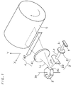
- Fig. 3 is a perspective view of an optical beam scanning system according to a first embodiment of the present invention.
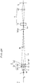
- Figs. 4A and 4B are views showing an optical system of the optical beam scanning system, taken in a Y-Z plane and an X-Z plane, respectively.
- the optical beam scanning system has the same structure as that of the conventional optical beam scanning system of Figs. 1, 2A and 2B, except for the structure of a first image-forming system 2.
- the structure except that of the first image-forming system 2 will not be explained here, and only the structure of the first image-forming system 2 will be described in detail. Instead, the symbols and the reference numbers used in describing the conventional optical beam scanning system are allotted to the corresponding parts, by which the structure of the novel optical beam scanning system is regarded as explained except for that of the first image-forming system 2.
- the first image-forming system 2 includes a first lens system 26 and a second lens system 27, the first lens system 26 being formed by a cylindrical lens which has a positive power along the direction of an axis of rotation 3b (Y direction), the second lens system 27 being formed by a cylindrical lens which has a positive power along the main scanning direction X.
- the first and the second lens systems 26 and 27 are disposed in that order from a light source 1 side to a rotary polygon mirror 3 side.
- a diverging light beam L1 from the light source 1 first enters the first lens system 26 where it is reshaped so as to converge onto a mirror surface 3a at a predetermined angle of ⁇ p with respect to the Y direction.
- the numerical aperture at the light source side is NA0 (i.e., divergence angle being ⁇ 0) though not shown in Figs. 4A and 4B).
- NA0 i.e., divergence angle being ⁇ 0
- the light beam thus passed through the first lens system 26 remains as diverging at an angle of ⁇ 0 since the first lens system 26 has no power along the X direction.
- the light beam from the first lens system 26 next enters a second lens system 27.
- the light beam L3 is reshaped by the second lens system 27 into a collimated light beam.
- reshaped light beam L3 is thereafter deflected by the rotary polygon mirror 3 to become a deflected light beam L4 which would be focused on the surface-to-be-scanned 5 through a second image-forming system 4 which is formed by a scanning lens 41 and a cylindrical lens 42.
- the light beam L3 can be focused on the mirror surface 3a, independently of how large the beam diameter ⁇ X of the light beam L3 for the X direction is.
- the first lens system 26 can be disposed in the vicinity of the light source 1 as shown in Fig. 4A. The nearer the first lens system 26 and the light source 1 becomes, the shorter the distance between the first lens system 26 and the rotary polygon mirror 3 becomes.
- the second lens system 27 since the light beam L3 must have the beam diameter ⁇ X (which is taken along the X direction) of a predetermined size, the second lens system 27 must be spaced from the light source 1 correspondingly to the beam diameter ⁇ X . In more particular words, the second lens system 27 must be spaced from the light source 1 by a distance equivalent to its focal length. Hence, it is not possible that the first image-forming system 2 has an optical path length which is shorter than the focal length of the second lens system 27. However, this reversely implies that, according to the first embodiment, the optical path length of the first image-forming system 2 can be reduced to as short as the focal length of the second lens system 27.
- the optical beam scanning system includes a first lens system 26 formed by an aspherical cylindrical lens, which would reduce aberrations, especially spherical aberration. That is, in the first lens system 26, a surface S26 facing toward a rotary polygon mirror 3 satisfies Eq. 1 below.
- Eq. 1 Eq. 1 below.
- the second lens system 27 has a surface S27 facing toward the rotary polygon mirror 3 which satisfies: where the symbols x, y and z represent distances taken along directions X, Y and Z from an origin, the origin being an intersection at which the surface S27 and the optical axis of the scanning system intersect, and
- Table 2 shows lens data of the first image-forming system 2 according to the first embodiment.
- Table 2 i r Xi r Yi d i n i k 1 ⁇ 6.442 2.0 1.492821 2 ⁇ -2.477 87.681 -0.995 3 401.492 ⁇ 5.0 1.492821 4 -52.780 ⁇ 23.904 -0.760
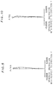
- Fig. 5 shows spherical aberration of the first image-forming system 2 having the lens data above, with respect to the direction Y.
- the optical beam scanning system requires the surface S 26 of the first lens system 26 to be aspherical, the surface S 26 may be simply cylindrical. However, considering correction of aberrations such as spherical aberration, the surface S 26 is preferably aspherical. Still another modification is possible wherein the both surfaces of the first lens system 26 are aspherical. The modifications as above are applicable not only to the first lens system 26 but also to the second lens system 27.
- the first lens system 26 and/or the second lens system 27 may be formed by more than one lenses, not by only one lens as suggested in the foregoing wherein the first embodiment has been described.
- a first and a second lens system 26 and 27 shown in Figs. 6A and 6B are also possible.
- two lenses 26a and 26b joined to each other form a cylindrical lens (first lens system) 26 which has a positive power along the direction Y (i.e., the direction of axis of rotation of the rotary polygon moirror).
- two lenses 27a and 27b joined to each other form a cylindrical lens (second lens system) 27 which has a positive power only along the main scanning direction X.
- the same effect as recited in relation to the first embodiment is obtainable with the first and the second lens systems 26 and 27 as such according to the second embodiment.
- Table 3 gives lens data of a first image-forming system 2 of the optical beam scanning system according to the second embodiment.
- Table 3 i r Xi r Yi d i n i 1 ⁇ ⁇ 1.0 1.609089 2 ⁇ 0.695 2.0 1.582509 3 ⁇ -2.082 87.993 4 319.575 ⁇ 1.5 1.609089 5 27.71 ⁇ 4.0 1.582509 6 -60.579 ⁇ 23.457
- Fig. 7 shows Y-direction spherical aberration of the first image-forming system 2 having the lens data as above.
- Figs. 8A and 8B show a first image-forming system 2 of an optical beam scanning system according to a third embodiment of the present invention.
- the first image-forming system 2 includes a first lens system 26 formed by a toroidal lens and a second lens system 27 formed by a cylindrical lens.
- the toroidal lens forming the first lens system 26 has a positive power along the Y direction (direction of the axis of rotation) and has a negative power along the main scanning direction X.
- the cylindrical lens forming the second lens system 27 has a positive power along the main scanning direction X.
- the first and the second lens systems 26 and 27 are disposed in that order from a light source 1 side to a rotary polygon mirror 3 side.
- a surface S26' facing toward the light source 1 is toroidal, whereas a surface S26 facing toward a mirror surface 3a of the rotary polygon mirror 3 is aspherical.
- a surface S27 facing toward the mirror surface 3a is aspherical.
- the surfaces S26 and S27 need not always be aspherical, but may simply be cylindrical. However, the surfaces S26 and S27 are preferred to be aspherical in order to reduce aberrations such as spherical aberration.
- the third embodiment has a large difference from the first embodiment in that the first lens system 26 has a positive power along the direction Y (direction of the axis of rotation) as well as a negative power along the main scanning direction X.
- the first lens system 26 has a positive power along the direction Y (direction of the axis of rotation) as well as a negative power along the main scanning direction X.
- the reason why the latter is possible is because the first lens system has a negative power along the main scanning direction.
- the focal length of a composite lens system consisting of the first and the second lens system is equal to that of the first and the second embodiment.
- the first image-forming system 2 has much reduced optical path length compared to the first and the second embodiment, without altering the numerical aperture from the light source, which eventually enables downsizing in the optical beam scanning system.
- the first and the second lens systems 26 and 27 have surfaces S26 and S27, respectively, each being aspherical as in the first embodiment.
- Table 4 gives lens data of a first image-forming system 2 according to the third embodiment.
- Table 4 i r Xi r Yi d i n i k 1 -1.077 4.575 1.0 1.492821 2 ⁇ -1.664 42.807 -1.06 3 178.343 ⁇ 5.0 1.492821 4 -26.696 ⁇ 27.686 -0.782
- Fig. 9 shows spherical aberration of the first image-forming system 2 whose lens data is given in Table 4, with respect to the direction Y.
- the present invention is not exclusively directed to the optical beam scanning system with such design.
- the present invention may be embodied as an optical beam scanning system of other design as given below, for instance.
- a first image-forming system 2 may be exactly the same in structure as the first image-forming system 2 of the first embodiment (Figs. 4A and 4B).
- the demand for reduction in spherical aberration requires that each surface of a first lens system 26 satisfies Eq. 3 below.
- the symbols x, y and z represent distances along directions X , Y and Z from an origin, the origin being an intersection at which each surface of the first lens system 26 and the optical axis of the scanning system intersect, and
- each surface of a second lens system 27 must satisfies: where the symbols x, y and z represent distances taken along directions X, Y and Z from an origin, the origin being an intersection at which each surface the second lens 27 and the optical axis of the scanning system intersect, and
- Table 5 shows lens data of the first image-forming system 2 as above.
- Fig. 10 shows spherical aberration of the first image-forming system 2 having the lens data above, with respect to the direction Y.
- a relatively short optical path length d is attained.
Landscapes
- Physics & Mathematics (AREA)
- General Physics & Mathematics (AREA)
- Optics & Photonics (AREA)
- Mechanical Optical Scanning Systems (AREA)
- Lenses (AREA)
Applications Claiming Priority (2)
| Application Number | Priority Date | Filing Date | Title |
|---|---|---|---|
| JP2253745A JP2559898B2 (ja) | 1990-09-21 | 1990-09-21 | 光ビーム走査装置 |
| JP253745/90 | 1990-09-21 |
Publications (3)
| Publication Number | Publication Date |
|---|---|
| EP0476698A2 true EP0476698A2 (de) | 1992-03-25 |
| EP0476698A3 EP0476698A3 (en) | 1992-09-09 |
| EP0476698B1 EP0476698B1 (de) | 1995-02-15 |
Family
ID=17255553
Family Applications (1)
| Application Number | Title | Priority Date | Filing Date |
|---|---|---|---|
| EP91116057A Expired - Lifetime EP0476698B1 (de) | 1990-09-21 | 1991-09-20 | Optisches Abtastsystem |
Country Status (4)
| Country | Link |
|---|---|
| US (1) | US5182668A (de) |
| EP (1) | EP0476698B1 (de) |
| JP (1) | JP2559898B2 (de) |
| DE (1) | DE69107384T2 (de) |
Cited By (8)
| Publication number | Priority date | Publication date | Assignee | Title |
|---|---|---|---|---|
| EP0658790A3 (de) * | 1993-12-17 | 1996-03-06 | Fuji Xerox Co Ltd | Kollimationslinse für optisches Abtastgerät. |
| EP0798587A3 (de) * | 1996-03-29 | 1998-09-02 | Sick AG | Lichtfleckerzeugungsvorrichtung |
| WO1999017149A1 (en) * | 1997-09-29 | 1999-04-08 | Eastman Kodak Company | Optical configuration for an optical scanner system |
| US5932151A (en) * | 1997-09-29 | 1999-08-03 | Imation Corp. | Method of making a flexible lens |
| US6002524A (en) * | 1997-09-29 | 1999-12-14 | Imation Corp. | Flexible lens |
| US6057537A (en) * | 1997-09-29 | 2000-05-02 | Eastman Kodak Company | Optical scanner feedback system having a reflected cylinder lens |
| US6094287A (en) * | 1998-12-03 | 2000-07-25 | Eastman Kodak Company | Wobble correcting monogon scanner for a laser imaging system |
| US6108025A (en) * | 1997-09-29 | 2000-08-22 | Eastman Kodak Company | Optical scanner system having a laser beam power attentuation mechanism |
Families Citing this family (3)
| Publication number | Priority date | Publication date | Assignee | Title |
|---|---|---|---|---|
| US5737112A (en) * | 1994-07-07 | 1998-04-07 | Asahi Kogaku Kogyo Kabushiki Kaisha | Scanning optical systems |
| US7817323B2 (en) * | 2007-07-02 | 2010-10-19 | Texas Instruments Incorporated | Optical structure and an imaging system using the same |
| US9116348B1 (en) * | 2012-10-02 | 2015-08-25 | The United States Of America As Represented By The Secretary Of The Army | Laser mapping tool and weapon replacement fixture |
Family Cites Families (10)
| Publication number | Priority date | Publication date | Assignee | Title |
|---|---|---|---|---|
| JPS5829489B2 (ja) * | 1974-07-23 | 1983-06-23 | 富士写真フイルム株式会社 | ヒカリソウサキノ ドウキコウサイシユホウホウ |
| US4123135A (en) * | 1977-06-30 | 1978-10-31 | International Business Machines Corporation | Optical system for rotating mirror line scanning apparatus |
| JPS54143659A (en) * | 1978-04-28 | 1979-11-09 | Canon Inc | Image forming optical system for semiconductor laser |
| GB2096789B (en) * | 1981-03-03 | 1985-03-13 | Canon Kk | Optical mechanical scanning system |
| JPS5868014A (ja) * | 1981-10-20 | 1983-04-22 | Canon Inc | ゴ−スト像を除去する走査光学系 |
| JPS5876810A (ja) * | 1981-10-31 | 1983-05-10 | Konishiroku Photo Ind Co Ltd | 光ビ−ム走査装置 |
| JPH0618420B2 (ja) * | 1984-02-24 | 1994-03-09 | 株式会社リコー | 画素密度変換可能な光走査装置 |
| JPH01231015A (ja) * | 1988-03-11 | 1989-09-14 | Fuji Xerox Co Ltd | 光学走査装置 |
| JPH0769521B2 (ja) * | 1988-07-13 | 1995-07-31 | 株式会社日立製作所 | 光走査装置及び走査レンズ |
| JPH02115814A (ja) * | 1988-10-25 | 1990-04-27 | Dainippon Screen Mfg Co Ltd | 光ビーム走査装置 |
-
1990
- 1990-09-21 JP JP2253745A patent/JP2559898B2/ja not_active Expired - Lifetime
-
1991
- 1991-09-20 DE DE69107384T patent/DE69107384T2/de not_active Expired - Fee Related
- 1991-09-20 US US07/764,143 patent/US5182668A/en not_active Expired - Fee Related
- 1991-09-20 EP EP91116057A patent/EP0476698B1/de not_active Expired - Lifetime
Cited By (9)
| Publication number | Priority date | Publication date | Assignee | Title |
|---|---|---|---|---|
| EP0658790A3 (de) * | 1993-12-17 | 1996-03-06 | Fuji Xerox Co Ltd | Kollimationslinse für optisches Abtastgerät. |
| EP0798587A3 (de) * | 1996-03-29 | 1998-09-02 | Sick AG | Lichtfleckerzeugungsvorrichtung |
| WO1999017149A1 (en) * | 1997-09-29 | 1999-04-08 | Eastman Kodak Company | Optical configuration for an optical scanner system |
| US5932151A (en) * | 1997-09-29 | 1999-08-03 | Imation Corp. | Method of making a flexible lens |
| US5933268A (en) * | 1997-09-29 | 1999-08-03 | Imation Corp. | Optical configuration for an optical scanner system |
| US6002524A (en) * | 1997-09-29 | 1999-12-14 | Imation Corp. | Flexible lens |
| US6057537A (en) * | 1997-09-29 | 2000-05-02 | Eastman Kodak Company | Optical scanner feedback system having a reflected cylinder lens |
| US6108025A (en) * | 1997-09-29 | 2000-08-22 | Eastman Kodak Company | Optical scanner system having a laser beam power attentuation mechanism |
| US6094287A (en) * | 1998-12-03 | 2000-07-25 | Eastman Kodak Company | Wobble correcting monogon scanner for a laser imaging system |
Also Published As
| Publication number | Publication date |
|---|---|
| US5182668A (en) | 1993-01-26 |
| JP2559898B2 (ja) | 1996-12-04 |
| EP0476698A3 (en) | 1992-09-09 |
| EP0476698B1 (de) | 1995-02-15 |
| DE69107384T2 (de) | 1995-07-20 |
| DE69107384D1 (de) | 1995-03-23 |
| JPH04131812A (ja) | 1992-05-06 |
Similar Documents
| Publication | Publication Date | Title |
|---|---|---|
| US5025268A (en) | Optical scanning apparatus and asymmetrical aspheric scanning lens | |
| JP3072061B2 (ja) | 光走査装置 | |
| US6222662B1 (en) | Optical scanning device and a scanning lens therefor | |
| US5604622A (en) | Laser scanning device | |
| US5052767A (en) | Optical beam scanning system | |
| US4674825A (en) | Scanning optical system | |
| US4818046A (en) | Light beam scanning device | |
| US5179465A (en) | Optical system for light beam scanning | |
| US6259546B1 (en) | Scanning and imaging lens and optical scanning device | |
| EP0476698B1 (de) | Optisches Abtastsystem | |
| US5343325A (en) | Optical scanning system with tilt correction function | |
| JPH1138348A (ja) | 走査結像光学系および光走査装置 | |
| US4919502A (en) | Tilt error corrective scanning optical system | |
| EP0387900A2 (de) | Optisches Abtastsystem | |
| US5477372A (en) | Optical scanner | |
| US6154303A (en) | Laser scanning system | |
| US5600475A (en) | Laser scanner | |
| US4882483A (en) | Optical scanning apparatus with optical correction for scan mirror surface tilt | |
| US5966232A (en) | Scanning optical system | |
| EP0629891B1 (de) | Optisches Abtastgerät | |
| US5148304A (en) | Optical beam scanning system | |
| KR950000087B1 (ko) | 광선비임 스캐닝용 광학시스템 | |
| JP3191538B2 (ja) | 走査レンズ及び光走査装置 | |
| US6670980B1 (en) | Light-scanning optical system | |
| JP4219429B2 (ja) | マルチビーム走査結像光学系における結像ミラーの製造方法 |
Legal Events
| Date | Code | Title | Description |
|---|---|---|---|
| PUAI | Public reference made under article 153(3) epc to a published international application that has entered the european phase |
Free format text: ORIGINAL CODE: 0009012 |
|
| AK | Designated contracting states |
Kind code of ref document: A2 Designated state(s): DE FR GB |
|
| PUAL | Search report despatched |
Free format text: ORIGINAL CODE: 0009013 |
|
| AK | Designated contracting states |
Kind code of ref document: A3 Designated state(s): DE FR GB |
|
| 17P | Request for examination filed |
Effective date: 19921019 |
|
| 17Q | First examination report despatched |
Effective date: 19940406 |
|
| GRAA | (expected) grant |
Free format text: ORIGINAL CODE: 0009210 |
|
| AK | Designated contracting states |
Kind code of ref document: B1 Designated state(s): DE FR GB |
|
| PG25 | Lapsed in a contracting state [announced via postgrant information from national office to epo] |
Ref country code: FR Effective date: 19950215 |
|
| REF | Corresponds to: |
Ref document number: 69107384 Country of ref document: DE Date of ref document: 19950323 |
|
| EN | Fr: translation not filed | ||
| PLBE | No opposition filed within time limit |
Free format text: ORIGINAL CODE: 0009261 |
|
| STAA | Information on the status of an ep patent application or granted ep patent |
Free format text: STATUS: NO OPPOSITION FILED WITHIN TIME LIMIT |
|
| 26N | No opposition filed | ||
| PGFP | Annual fee paid to national office [announced via postgrant information from national office to epo] |
Ref country code: GB Payment date: 20010919 Year of fee payment: 11 |
|
| PGFP | Annual fee paid to national office [announced via postgrant information from national office to epo] |
Ref country code: DE Payment date: 20011009 Year of fee payment: 11 |
|
| REG | Reference to a national code |
Ref country code: GB Ref legal event code: IF02 |
|
| PG25 | Lapsed in a contracting state [announced via postgrant information from national office to epo] |
Ref country code: GB Free format text: LAPSE BECAUSE OF NON-PAYMENT OF DUE FEES Effective date: 20020920 |
|
| PG25 | Lapsed in a contracting state [announced via postgrant information from national office to epo] |
Ref country code: DE Free format text: LAPSE BECAUSE OF NON-PAYMENT OF DUE FEES Effective date: 20030401 |
|
| GBPC | Gb: european patent ceased through non-payment of renewal fee |
Effective date: 20020920 |