EP0477067B1 - Hochleistungsfähiger pneumatischer Schlagmechanismus mit Kolbenventil - Google Patents
Hochleistungsfähiger pneumatischer Schlagmechanismus mit Kolbenventil Download PDFInfo
- Publication number
- EP0477067B1 EP0477067B1 EP91402424A EP91402424A EP0477067B1 EP 0477067 B1 EP0477067 B1 EP 0477067B1 EP 91402424 A EP91402424 A EP 91402424A EP 91402424 A EP91402424 A EP 91402424A EP 0477067 B1 EP0477067 B1 EP 0477067B1
- Authority
- EP
- European Patent Office
- Prior art keywords
- air
- cylinder
- piston
- plunger valve
- air inlet
- Prior art date
- Legal status (The legal status is an assumption and is not a legal conclusion. Google has not performed a legal analysis and makes no representation as to the accuracy of the status listed.)
- Expired - Lifetime
Links
Images

Classifications
-
- B—PERFORMING OPERATIONS; TRANSPORTING
- B25—HAND TOOLS; PORTABLE POWER-DRIVEN TOOLS; MANIPULATORS
- B25D—PERCUSSIVE TOOLS
- B25D9/00—Portable percussive tools with fluid-pressure drive, i.e. driven directly by fluids, e.g. having several percussive tool bits operated simultaneously
- B25D9/14—Control devices for the reciprocating piston
Definitions
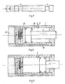
- the air channel 43 extends from its inlet port 45 at the rear inner wall of the cylinder 1 to the right end of a plunger valve cylinder 52, while the air channel 44 extends from its inlet port 46 to the left end of the plunger valve cylinder 52.
- the inlet channels 41 and 38 are all connected to compressed air source.
- a rear chamber 29 of the cylinder 1 is provided with an air inlet channel 12 for forward stroke and an air exhaust channel 60 for backward stroke, and, on the other hand, a front chamber 28 is provided with an air inlet channel 11 for backward stroke and an air exhaust channel 59 for forward stroke.
- the air exhaust channels 59 and 60 can be respectively connected to atmosphere through two annular grooves 71 and 72 of the plunger valve 5.
- the radial air channel 42 is connected to the air channel 43, to feed air to the right side of the plunger valve cylinder 52.
- the plunger valve 5 moves to the left end of the cylinder 52, as shown in Fig. 2.
- the rear chamber 29 is connected with the air inlet channel 12 for forward stroke and the annular groove 72 of the valve 5, and the air exhaust channel 59 for forward stroke is open, while the air inlet channel 11 and air exhaust channel 60 for backward stroke are shut off. Therefore, another forward stroke begins.
Landscapes
- Physics & Mathematics (AREA)
- Fluid Mechanics (AREA)
- Engineering & Computer Science (AREA)
- Mechanical Engineering (AREA)
- Actuator (AREA)
- Percussive Tools And Related Accessories (AREA)
- Earth Drilling (AREA)
- Fluid-Pressure Circuits (AREA)
Claims (4)
- Hochleistungsfähiger, pneumatischer Schlagmechanismus, mit einem ersten Zylinder (1) mit einer hinteren Kammer (29) und einer vorderen Kammer (28) und mit einem Kolben (2) mit einem hinteren Luftverteilerstab (4) und einem vorderen Luftverteilerstab (3), der auch als ein Arbeitskopf wirkt, wobei der hintere Verteilerstab (4) einen axial verlaufenden Lufteinlaßkanal (41) hat, welcher über einen radial verlaufenden Luftkanal (42) in dem Kolben (2) alternativ mit einem Paar Lufteinlaßkanälen (43 und 44) verbunden werden kann, dadurch gekennzeichnet,
daß er ferner ein Kolbenventil (5) aufweist, das entlang eines zweiten Zylinders bewegbar ist, welcher mit den Lufteinlaßkanälen (43,44) verbunden ist, und
daß die vorderen und hinteren Luftverteilerstäbe (3,4) Teile mit größerem Durchmesser (17,18) und mit kleinerem Durchmesser (15,16) haben, wobei die Luftverteilerstäbe (3,4) mit ringförmigen Nuten versehen sind, um zusammen mit dem Kolbenventil (5) vorherbestimmte Mengen an Luft, welche in den ersten Zylinder (1) gelangt ist, während eines Vorwärts- und eines Rückwärtshubes des Kolbens (2) zu steuern. - Schlagmechanismus nach Anspruch 1, bei welchem ein zweiter Zylinder (52) des Kolbenventils (5) zusammen mit dem ersten Zylinder (1) in demselben Körper untergebracht ist, wobei der erste Zylinder (1) eine hintere Abdeckung (49) und eine vordere Abdeckung (19) sowie einen hinteren Pufferkolben (7) und einen vorderen Pufferkolben (6) mit zwei dazwischen ausgebildeten Pufferkammern (31 und 30) hat, wobei die Kolben (7 und 6) jeweils einen radial verlaufenden Lufteinlaßkanal (12 und 11) haben, die für Vorwärts- und Rückwärtshübe entsprechend bemessen sind.
- Schlagmechanismus nach einem der Ansprüche 1 oder 2, bei welchem der erste Zylinder (1) an seinen vorderen und rückwärtigen Enden mit Lufteinlaßkanälen (11,59) und Luftauslaßkanälen versehen ist, und das Kolbenventil (5) an seinen beiden Enden mit ringförmigen Nuten (71 und 72) versehen ist, um die Kanäle (11,59 und 12,60) zu öffnen oder zu schließen.
- Schlagmechanismus nach Anspruch 3, dadurch gekennzeichnet, daß eine Einwärtsbewegung der Pufferkolben (6,7) durch entsprechende Schultern (32,33) begrenzt ist, welche an der Innenwandung des ersten Zylinders (1) ausgebildet sind.
Applications Claiming Priority (2)
| Application Number | Priority Date | Filing Date | Title |
|---|---|---|---|
| CN90220630 | 1990-09-15 | ||
| CN90220630U CN2080099U (zh) | 1990-09-15 | 1990-09-15 | 柱塞滑阀高效气动冲击机构 |
Publications (2)
| Publication Number | Publication Date |
|---|---|
| EP0477067A1 EP0477067A1 (de) | 1992-03-25 |
| EP0477067B1 true EP0477067B1 (de) | 1993-08-25 |
Family
ID=4899028
Family Applications (1)
| Application Number | Title | Priority Date | Filing Date |
|---|---|---|---|
| EP91402424A Expired - Lifetime EP0477067B1 (de) | 1990-09-15 | 1991-09-12 | Hochleistungsfähiger pneumatischer Schlagmechanismus mit Kolbenventil |
Country Status (6)
| Country | Link |
|---|---|
| US (1) | US5199504A (de) |
| EP (1) | EP0477067B1 (de) |
| JP (1) | JPH0688216B2 (de) |
| CN (1) | CN2080099U (de) |
| DE (1) | DE69100306T2 (de) |
| RU (1) | RU2043546C1 (de) |
Families Citing this family (10)
| Publication number | Priority date | Publication date | Assignee | Title |
|---|---|---|---|---|
| SE9202105L (sv) * | 1992-07-07 | 1994-01-08 | Atlas Copco Rocktech Ab | Slagverk |
| US5556649A (en) * | 1993-08-30 | 1996-09-17 | Yamaha Motor Co., Ltd. | Device for removing runners from molded products |
| US5887665A (en) * | 1994-08-19 | 1999-03-30 | Synthes (U.S.A.) | Striking element |
| NO179879C (no) * | 1994-10-12 | 1997-01-08 | Statoil As | Trykkforsterker (III) |
| JP4494071B2 (ja) * | 2004-04-08 | 2010-06-30 | 株式会社テクノサカト | 油圧を利用した破砕装置 |
| CN101457633B (zh) * | 2008-12-25 | 2010-12-15 | 浙江大学 | 活塞位移电反馈负载口独立控制液压冲击器 |
| CN103097654A (zh) * | 2010-09-10 | 2013-05-08 | 澳大利亚凿岩设备制造与维护有限公司 | 改进的凿岩钻机 |
| CN103557348B (zh) * | 2013-11-06 | 2016-08-31 | 福州德格索兰机械有限公司 | 用于ty24c型凿岩机的阀组 |
| CN105314123A (zh) * | 2014-06-20 | 2016-02-10 | 徐延明 | 一种航母弹射器的控制阀 |
| CN110984843B (zh) * | 2019-12-29 | 2021-09-10 | 东台市高科技术创业园有限公司 | 一种液压冲击钻动力装置 |
Family Cites Families (17)
| Publication number | Priority date | Publication date | Assignee | Title |
|---|---|---|---|---|
| US428672A (en) * | 1890-05-27 | Eichard l | ||
| DE553604C (de) * | 1932-06-28 | Josef Kern | Pressluftwerkzeug | |
| US816021A (en) * | 1903-06-22 | 1906-03-27 | John George Leyner | Drill-bit-rotating mechanism for rock-drilling engines. |
| US909923A (en) * | 1907-09-14 | 1909-01-19 | Jonas L Mitchell | Valve mechanism for rock-drills, &c. |
| US1401003A (en) * | 1916-10-16 | 1921-12-20 | Denver Rock Drill Mfg Co | Motor |
| US1740713A (en) * | 1923-12-17 | 1929-12-24 | Sullivan Machinery Co | Fluid-pressure motor |
| US2210020A (en) * | 1939-01-23 | 1940-08-06 | Anderson Norman | Power hammer |
| US2228338A (en) * | 1940-08-03 | 1941-01-14 | Ingersoll Rand Co | Rock drill |
| US2831933A (en) * | 1956-03-02 | 1958-04-22 | Westinghouse Electric Corp | Circuit interrupters |
| ZA761650B (en) * | 1976-03-17 | 1977-07-27 | Steel Eng Co Ltd | Hydraulic percussive machines |
| IT1103805B (it) * | 1978-06-07 | 1985-10-14 | Tongiani Enzo | Martello pneumatico perfezionato |
| US4240332A (en) * | 1978-08-25 | 1980-12-23 | Arkwin Industries, Inc. | Fluid operated locking actuator |
| FR2454875A1 (fr) * | 1979-04-25 | 1980-11-21 | Pt Instit | Machine pneumatique a percussion |
| US4418769A (en) * | 1981-03-12 | 1983-12-06 | Cooper Industries, Inc. | Hammer starting mechanism |
| US4448262A (en) * | 1982-05-19 | 1984-05-15 | Cooper Industries, Inc. | Pneumatic hammer |
| ZA869271B (en) * | 1985-12-09 | 1987-10-28 | Aclo Pty Ltd | A pneumatic tool |
| FR2647870B1 (fr) * | 1989-06-06 | 1991-09-06 | Eimco Secoma | Appareil de percussion hydraulique avec dispositif d'amortissement des ondes de choc en retour |
-
1990
- 1990-09-15 CN CN90220630U patent/CN2080099U/zh not_active Expired - Lifetime
-
1991
- 1991-09-03 US US07/753,731 patent/US5199504A/en not_active Expired - Fee Related
- 1991-09-12 JP JP3261232A patent/JPH0688216B2/ja not_active Expired - Lifetime
- 1991-09-12 EP EP91402424A patent/EP0477067B1/de not_active Expired - Lifetime
- 1991-09-12 DE DE91402424T patent/DE69100306T2/de not_active Expired - Fee Related
- 1991-09-13 RU SU915001433A patent/RU2043546C1/ru active
Also Published As
| Publication number | Publication date |
|---|---|
| JPH0688216B2 (ja) | 1994-11-09 |
| RU2043546C1 (ru) | 1995-09-10 |
| CN2080099U (zh) | 1991-07-03 |
| DE69100306D1 (de) | 1993-09-30 |
| JPH04256587A (ja) | 1992-09-11 |
| US5199504A (en) | 1993-04-06 |
| EP0477067A1 (de) | 1992-03-25 |
| DE69100306T2 (de) | 1994-04-21 |
Similar Documents
| Publication | Publication Date | Title |
|---|---|---|
| EP0477067A1 (de) | Hochleistungsfähiger pneumatischer Schlagmechanismus mit Kolbenventil | |
| US5113950A (en) | For percussive tools, a housing, a pneumatic distributor, and a hammer piston means therefor | |
| US4440237A (en) | Pavement breaker | |
| US6899206B2 (en) | Air cylinder with high frequency shock absorber and accelerator | |
| US3602103A (en) | Slide-latch valve for air-driven tools | |
| US5064005A (en) | Impact hammer and control arrangement therefor | |
| US4150603A (en) | Fluid operable hammer | |
| RU2056998C1 (ru) | Пневматическая машина ударного действия | |
| US4261249A (en) | Hammer | |
| US4819542A (en) | Percussive tool | |
| RU2244828C1 (ru) | Пневматический молоток | |
| SU1406363A1 (ru) | Устройство ударного действи | |
| CA1121231A (en) | Fluid operable hammer or impactor | |
| CN88204592U (zh) | 双阀高效气动冲击机构 | |
| RU2015321C1 (ru) | Пневматический молоток с дроссельным воздухораспределением | |
| US4418769A (en) | Hammer starting mechanism | |
| JPH0540951Y2 (de) | ||
| RU2747151C1 (ru) | Пневматический молот | |
| CN2334548Y (zh) | 液压锤 | |
| SU895646A2 (ru) | Пневматический пистолет дл забивки гвоздей | |
| SU768961A1 (ru) | Пневматическа машина ударного действи | |
| GB2079214A (en) | Improvements in or Relating to Impact Tools and Like Percussive Apparatus | |
| JPS6355435B2 (de) | ||
| CS269074B1 (cs) | Pneumatické kladivo | |
| JPH0243666Y2 (de) |
Legal Events
| Date | Code | Title | Description |
|---|---|---|---|
| PUAI | Public reference made under article 153(3) epc to a published international application that has entered the european phase |
Free format text: ORIGINAL CODE: 0009012 |
|
| AK | Designated contracting states |
Kind code of ref document: A1 Designated state(s): DE FR GB SE |
|
| 17P | Request for examination filed |
Effective date: 19920312 |
|
| 17Q | First examination report despatched |
Effective date: 19920624 |
|
| GRAA | (expected) grant |
Free format text: ORIGINAL CODE: 0009210 |
|
| AK | Designated contracting states |
Kind code of ref document: B1 Designated state(s): DE FR GB SE |
|
| REF | Corresponds to: |
Ref document number: 69100306 Country of ref document: DE Date of ref document: 19930930 |
|
| ET | Fr: translation filed | ||
| PLBE | No opposition filed within time limit |
Free format text: ORIGINAL CODE: 0009261 |
|
| STAA | Information on the status of an ep patent application or granted ep patent |
Free format text: STATUS: NO OPPOSITION FILED WITHIN TIME LIMIT |
|
| 26N | No opposition filed | ||
| EAL | Se: european patent in force in sweden |
Ref document number: 91402424.5 |
|
| PGFP | Annual fee paid to national office [announced via postgrant information from national office to epo] |
Ref country code: FR Payment date: 20000811 Year of fee payment: 10 |
|
| PGFP | Annual fee paid to national office [announced via postgrant information from national office to epo] |
Ref country code: GB Payment date: 20000905 Year of fee payment: 10 |
|
| PGFP | Annual fee paid to national office [announced via postgrant information from national office to epo] |
Ref country code: DE Payment date: 20000915 Year of fee payment: 10 |
|
| PGFP | Annual fee paid to national office [announced via postgrant information from national office to epo] |
Ref country code: SE Payment date: 20010822 Year of fee payment: 11 |
|
| PG25 | Lapsed in a contracting state [announced via postgrant information from national office to epo] |
Ref country code: GB Free format text: LAPSE BECAUSE OF NON-PAYMENT OF DUE FEES Effective date: 20010912 |
|
| GBPC | Gb: european patent ceased through non-payment of renewal fee |
Effective date: 20010912 |
|
| PG25 | Lapsed in a contracting state [announced via postgrant information from national office to epo] |
Ref country code: DE Free format text: LAPSE BECAUSE OF NON-PAYMENT OF DUE FEES Effective date: 20020501 |
|
| PG25 | Lapsed in a contracting state [announced via postgrant information from national office to epo] |
Ref country code: FR Free format text: LAPSE BECAUSE OF NON-PAYMENT OF DUE FEES Effective date: 20020531 |
|
| REG | Reference to a national code |
Ref country code: FR Ref legal event code: ST |
|
| PG25 | Lapsed in a contracting state [announced via postgrant information from national office to epo] |
Ref country code: SE Free format text: LAPSE BECAUSE OF NON-PAYMENT OF DUE FEES Effective date: 20020913 |
|
| EUG | Se: european patent has lapsed |