EP0477563B1 - Distributeur de fluide - Google Patents
Distributeur de fluide Download PDFInfo
- Publication number
- EP0477563B1 EP0477563B1 EP91114414A EP91114414A EP0477563B1 EP 0477563 B1 EP0477563 B1 EP 0477563B1 EP 91114414 A EP91114414 A EP 91114414A EP 91114414 A EP91114414 A EP 91114414A EP 0477563 B1 EP0477563 B1 EP 0477563B1
- Authority
- EP
- European Patent Office
- Prior art keywords
- medium reservoir
- mounting support
- actuating
- snap
- discharge apparatus
- Prior art date
- Legal status (The legal status is an assumption and is not a legal conclusion. Google has not performed a legal analysis and makes no representation as to the accuracy of the status listed.)
- Expired - Lifetime
Links
- 239000012530 fluid Substances 0.000 title abstract 3
- 238000003780 insertion Methods 0.000 claims abstract description 22
- 230000037431 insertion Effects 0.000 claims abstract description 22
- 238000000034 method Methods 0.000 abstract 1
- 238000004519 manufacturing process Methods 0.000 description 2
- 230000000149 penetrating effect Effects 0.000 description 1
- 230000035515 penetration Effects 0.000 description 1
- 230000003319 supportive effect Effects 0.000 description 1
Images
Classifications
-
- B—PERFORMING OPERATIONS; TRANSPORTING
- B05—SPRAYING OR ATOMISING IN GENERAL; APPLYING FLUENT MATERIALS TO SURFACES, IN GENERAL
- B05B—SPRAYING APPARATUS; ATOMISING APPARATUS; NOZZLES
- B05B11/00—Single-unit hand-held apparatus in which flow of contents is produced by the muscular force of the operator at the moment of use
- B05B11/01—Single-unit hand-held apparatus in which flow of contents is produced by the muscular force of the operator at the moment of use characterised by the means producing the flow
- B05B11/02—Membranes or pistons acting on the contents inside the container, e.g. follower pistons
Definitions
- the invention relates to a discharge device according to the preamble of claim 1.
- discharge device manual actuation, e.g. one or more discharge conveyors are actuated by finger pressure on opposite printing surfaces in such a way that a certain amount of medium is discharged or pressed out of one or more media stores or the respective discharge conveyor through an outlet channel to one or more discharge openings and through these into the open.
- the media storage is expediently partially or substantially completely enclosed within at least one of the actuation units.
- the design can be such that at least the associated actuation unit must be opened for this purpose or detached from the other actuation unit. Only after Inserting the media memory or media, the actuation units can be assembled. Regardless of whether the media storage is already used in the manufacture of the discharge device or only by the user, this type of assembly can be cumbersome, time-consuming and prone to errors.
- EP-A-0 065 432 shows a discharge device with a mounting jacket, from one end of which a pump and from the other end of which an open media storage device is to be used, the media storage device being only surrounded by the mounting jacket and the connection of the two actuating units which can be moved relative to one another not can also be seen.
- one actuating part is formed directly by the media store, so that it cannot be received in a holder of one of two actuating units.
- the media storage device is only surrounded on the outer circumference by a single mounting jacket or the mounting jacket is not spaced from the inner circumference of a housing jacket.
- the invention is further based on the object of providing a discharge device of the type mentioned, which disadvantages of known designs or of the type described are avoided and which, in particular, ensures very simple assembly of the media store.
- the discharge actuation with both areas to be moved against each other via the actuation stroke forms a preassembled, one-piece or formed by separate components, which can be completed or assembled as an assembly or assembly before the media storage is used.
- this assembly module has an externally accessible holder, into which the media storage device can be inserted at any time so that it is then in a functional position, e.g. already connected to the discharge conveyor or the outlet channel or by a switching movement into it Connection position can be transferred.
- This makes the Training according to the invention is also particularly good for automated production, because namely the discharge device can be completely prefabricated except for the arrangement of the media store and then the previously filled media store can be inserted and secured in a single assembly movement and without separate fastening parts.
- the media store expediently forms part of the discharge conveyor itself, namely in addition to its storage function e.g. an elastic, but preferably a dimensionally stable pressure or pump chamber, the chamber volume of which is reduced by the actuation.
- the stored medium can then be squeezed out either in a single actuation stroke at once or by stroke-limited partial strokes in metered quantities.
- the assembly of the discharge actuation expediently forms a substantially closed, for example approximately cylindrical, housing on the circumference and / or on one or both end faces, which has the discharge opening on one end or one side and an insertion opening on another side, in particular away from it for the media store, which has a cross-section which is substantially smaller than the surface extent of this side, so that the boundaries of the insertion opening and / or an end section of the media store lying in the region of the insertion opening can form an actuating handle or pressure surface.
- the insertion opening can be partially or completely closed by the media store used without additional means.
- the media storage device can be opened at a front end in the insertion direction during insertion to a width which essentially corresponds to its remaining inner width.
- the filled media store is then closed at the open end when inserted into the assembly by an engagement member provided on the assembly, which forms a pump piston or an additional guide or centering of the actuating units and the media store against each other.
- the actuation units are secured to one another by at least one additional guide.
- a guide can be formed by overlapping cap sleeves of the actuating units or through overlapping sleeves which are spaced within the outer shell of the assembly, these additional guides spacing the engagement member or the media storage on the outer circumference.
- the two actuation units are expediently also secured positively against pulling off from one another by stops, these stops being able to form a snap connection which automatically engages when the two actuation units are assembled.
- the media storage is expediently also fastened by an approximately linear plug-in movement which can be approximately rectified or parallel to the plug-in movement with which the actuating units are assembled.
- a further snap connection separate from the snap connection between the actuation units and / or at an axial distance therefrom is advantageously provided, which directly fixes the media container only in relation to one of the two actuation units, expediently free of play both in and against the direction of insertion.
- This snap connection can also be made by inserting the media container accordingly Snap resilient training by itself.
- inclined insertion surfaces can be provided for the latching members and / or the storage area, which are expediently attached essentially only in the edge region of the insertion opening, so that the media storage area on the outer circumference can have constant cross sections essentially over its entire length.
- the corresponding snap connection can also form an anti-rotation device for the media store.
- the media store When inserting, the media store can be held particularly securely if it has a gripper member at its rear end, on which it is attached with a e.g. mandrel-shaped gripper can be precisely aligned and picked up essentially without play.
- This gripper member which can be formed by an extension of the sleeve jacket of the media store which projects freely over a bottom wall, is expediently formed in one piece with the rest of the media store and has stops or snap members of the snap connection.
- the remaining longitudinal section of the media store can be supported on the outer circumference, if necessary, with radial prestressing relative to the associated actuating unit, so that the media store is secured against deformations under the discharge pressures that occur even with a relatively thin-walled design.
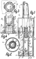
- the discharge device 1 has a compressible discharge actuation 2 for a discharge conveyor 3 lying completely in it with two essentially dimensionally stable actuation units 4, 5, which form a closed housing 6.
- each actuating unit 4 or 5 forms a cap 7 or 8, and the caps are put together.
- the discharge conveyor 3 lying completely inside the housing 6 can have one or more pumps, media stores 10, pump pistons 11, outlet channels 13 and / or discharge openings 14, for example in such a way that a pump piston 11 can be inserted one after the other into a series of media stores 10, which according to Art a turret arrangement are arranged in a ring.
- the parts mentioned are only provided in a simple manner and lie essentially in a common axis and essentially completely inside the housing 6.
- a discharge nozzle lying approximately in the central axis mentioned 16 to the outside, which has the discharge opening 14 in the region of its free end and can be covered with this by a removable closure cap 17, which can be preassembled independently of the media store 10.
- a holder 20 is provided, which projects substantially free of the end wall 21 of the cap 7 into the housing 6 and with its free end approximately up to the level of open end face of the cap shell 18 can range.
- the outside of the end wall 21 forms an actuator 22 of the discharge actuator 2, and the holder 20 does not protrude beyond the pressure surface forming this actuator 22, but is essentially flush with it.
- the other actuator 23 is formed by the end face of the end wall 15 facing away from it and arranged in a ring around the discharge nozzle 16.
- the bracket 20 is by a the insertion opening 24 penetrating the end wall 21, the boundary of which lies at a radial distance within the outer or inner circumference of the casing of the housing 6 and which is formed by the associated end of a mounting shaft 25.
- the support shaft 25 is formed by the inner circumference of a sleeve 26 which is formed in one piece with the end wall 21 and projects from it freely inward and which is closely matched to the outer circumference of the media store 10 and accommodates it essentially over its entire length.
- a snap connection 27 is provided between the media store 10 and the sleeve 26, which snaps into place when the media store 10 is inserted through the insertion opening 24 and has reached its mounting position.
- the jacket of the sleeve 26 forms following the end wall 21 at two or more locations distributed over the circumference radially outwardly projecting projections 28, which on their inner sides are opposed longitudinal grooves 29 for the displaceable reception of snap cams 30, which over protrude the outer circumference of the media store 10 at most by the wall thickness of the sleeve 26 and are formed in one piece with the media store 10.
- the grooves 29 have, following the outer end face of the end wall 21, insertion bevels which are assigned correspondingly inclined end faces at the front ends of the snap cams 30.
- the inner ends of the grooves 29 are substantially closed by corresponding inclined surfaces, but can be resiliently pressed apart by the inclined end surfaces of the snap cams 30 so that the snap cams 30 drive over them and then can engage behind the inner end surfaces of the projections 28.
- Each snap cam 30 then lies in the associated end of a longitudinal slot 31 of the jacket of the sleeve 26, this slot 31 can go through to the free end of the sleeve 26.
- the slot 31 adjoins the respective end face of the projection 28, in the area of which the sleeve 26 is closed over the circumference and which forms an anti-rotation device for the media store 10.
- the insertion movement of the media store 10 is limited by two stops 32 which are offset in the circumferential direction with respect to the snap cams 30 and which also protrude in one piece over the outer circumference of the media store 10, which engage in pockets 33 on the inner circumference of the sleeve 26 or the insertion opening 24 and also one Form anti-rotation lock.
- the stops 32 strike the bottom surfaces of the pockets 33 at the moment when the snap cams 30 come into a latched position, so that the media store 10 is then secured in a form-fitting and non-detachable manner in both opposite directions.
- a releasable connection to the actuating unit 4 is also conceivable for the interchangeable arrangement of the media store 10.
- the snap cams 30 lie axially immediately adjacent to a bottom wall 34 which is in one piece with the storage device, namely on an extension 35 of the casing 37 of the media storage device 10 projecting beyond the outside thereof.
- This sleeve-shaped extension 35 forms a gripper member 36 which is open at the rear end of the media storage device 10 for centering Picking up the media storage 10 with a suitable gripper and in the installed position lies completely within the insertion opening 34.
- the stops 32 are also provided. Due to the position described, the snap cams 30 are securely supported against relative movements relative to the jacket 37.
- the inner circumference of the media store 10 forms approximately from the bottom wall 34 to the open, slightly funnel-like Widened end of a cylinder track 12 for the pump piston 11, which is attached to the end of a plunger projecting freely beyond the inside of the end wall 15 and formed in one piece with the actuating unit 5 by inserting a piston shaft.
- the pump piston 11 projects beyond the open end face of the cap jacket 19.
- the two actuating units 4, 5 are already secured to one another against axial pulling apart and twisting by at least one snap connection 39 and at least one guide 42, 43.
- a guide 42 is formed by the two interlocking cap sleeves 18, 19. From the end wall 15 of the cap 8, a further sleeve 38, which is spaced within the cap jacket 19, projects inward, which forms the further guide 43 and the snap connection 39 with the sleeve 26.
- the sleeve 38 which is formed in one piece with the actuating unit 5, has at least one radially inwardly projecting, cam-like snap member 41 in the region of the free end and is divided by longitudinal slots into at least two or three circumferentially adjacent shell segments which are spread apart in a resilient manner can and each have a corresponding segment-shaped snap member 41.
- the sleeve 26 has a corresponding, radially outwardly projecting, annular collar-shaped snap member 40.
- the snap members 41 can slide on the outer circumference of the sleeve 26 at the same time.
- the pump piston 11 forms a further engagement member 44 for the mutually supportive connection of the two actuation units 4, 5. If this engagement member 44 is not a pump piston, it serves essentially only for closing or connecting the media store 10 when inserted.
- the engagement member 44 projects beyond the free end of the sleeve 38, which in turn extends approximately to the free end of the cap jacket 19 or is slightly set back relative to the latter.
- each pump stroke is stop limited by a controller 45 which e.g. is formed by cam webs 46 on the outer circumference of the cap shell 18 and stepped cam grooves 47 on the inner circumference of the cap shell 19.
- a controller 45 which e.g. is formed by cam webs 46 on the outer circumference of the cap shell 18 and stepped cam grooves 47 on the inner circumference of the cap shell 19.
- the two actuating units 4, 5 are rotated relative to one another in such a way that the cam webs 46 can come into engagement with the next, longer cam grooves 47.
- This control 45 and possibly a display device for discharge operations thus also belong to the preassembled module 49, in which the media storage 10 is to be inserted subsequently.
Landscapes
- Containers And Packaging Bodies Having A Special Means To Remove Contents (AREA)
- Electrical Discharge Machining, Electrochemical Machining, And Combined Machining (AREA)
- Photographic Developing Apparatuses (AREA)
- Nozzles (AREA)
- Rotary Pumps (AREA)
- Supply Devices, Intensifiers, Converters, And Telemotors (AREA)
Claims (13)
- Distributeur de fluides avec un dispositif d'actionnement (2) pour un refouleur de distribution (3), dispositif qui présente au moins deux unités d'actionnement (4, 5) pouvant être déplacées l'une par rapport à l'autre sur une course d'actionnement et formant au moins une périphérie, au moins un support (20), sur une première unité d'actionnement (4), pour au moins un réservoir de fluide (10) raccordé dans une position de fixation au refouleur de distribution (3), et au moins un canal d'évacuation (13) sur une deuxième unité d'actionnement (5), au moins deux unités d'actionnement (4, 5) formant notamment un groupe de construction préassemblé (49) et au moins un réservoir de fluide (10) pouvant être installé sur le support (20) de ce groupe de construction préassemblé (49), caractérisé en ce que les unités d'actionnement (4, 5) forment au moins un capuchon avec au moins une enveloppe de capuchon (18, 19), en ce qu'au moins un support (20) se trouve sur la première unité d'actionnement (4) à distance de la périphérie intérieure de l'enveloppe de capuchon (18, 19), et en ce que le support (20) est assemblé à la deuxième unité d'actionnement (5) par l'intermédiaire d'un moyen d'assujettissement (39) qui empêche sa séparation par traction.
- Distributeur selon la revendication 1, caractérisé en ce que le support (20) pour au moins un réservoir de fluide (10) est prévu pour l'essentiel sur seulement une des unités d'actionnement (4, 5) et est notamment conçu pour la fixation en position sensiblement sans jeu du réservoir de fluide (10) distinct du support (20), en ce que, de préférence, l'autre unité d'actionnement (5) présente un poussoir pour au moins un organe d'engagement (44) pour l'engagement direct par déplacement dans le réservoir de fluide (10), en ce que, notamment, l'organe d'engagement (44) s'engage en coulissement à l'intérieur du réservoir de fluide (10) ou encore est formé par un piston de pompe (11) d'une pompe à piston (9), piston qui est disposé à l'extrémité d'une tige de piston, faisant librement saillie dans le groupe de construction (49), d'une (5) des unités d'actionnement, et en ce que, de préférence, le réservoir de fluide (10) forme un cylindre de pompe sensiblement sur la totalité de son développement longitudinal, et/ou le moyen d'assujettissement (39) est prévu sur une périphérie d'au moins une unité d'actionnement (4, 5).
- Distributeur selon la revendication 1 ou 2, caractérisé en ce qu'au moins un réservoir de fluide (10) forme directement une chambre de refoulement ou encore de pompe du refouleur de distribution (3), en ce qu'est prévu, de préférence, un obturateur fermant le réservoir de fluide (10) avant l'atteinte de sa position de fixation, et/ou la chambre de refoulement présente une ouverture de chambre à fermer par un organe d'engagement (44) d'une unité d'actionnement (5) lors de l'insertion dans le support (20), et en ce qu'est notamment prévu sur l'organe d'engagement (44) un canal d'évacuation (13) menant à une ouverture de distribution (14).
- Distributeur selon une des revendications précédentes, caractérisé en ce que le groupe de construction préassemblé (49) forme un boîtier essentiellement fermé (6), constitué notamment de seulement deux capuchons de boîtier (7, 8) s'engageant l'un dans l'autre par coulissement, en ce que le boîtier (6) présente, dans une paroi extérieure (21), une ouverture d'insertion (24) pour le réservoir de fluide (10) à disposer de préférence en étant sensiblement totalement escamoté à l'intérieur du boîtier (6), et/ou en ce que la délimitation de l'ouverture d'insertion (24), située notamment dans une paroi frontale (21), constitue au moins une partie du support (20) ou encore se trouve à l'extrémité d'un puits de soutien (25) s'étendant sur la majeure partie de la longueur du réservoir de fluide (10), le réservoir de fluide (10) formant de préférence une fermeture essentiellement étanche de l'ouverture d'insertion (24), en présentant notamment un prolongement (35) dépassant d'une paroi de fond (34) et/ou une largeur extérieure sensiblement constante sur toute sa longueur.
- Distributeur selon une des revendications précédentes, caractérisé en ce que le support (20) est conçu pour la fixation en position par engagement positif du réservoir de fluide (10) dans la direction longitudinale et/ou périphérique de ce dernier, et forme de préférence exclusivement un assemblage par emboîtement, notamment à engagement automatique, pour le réservoir de fluide (10).
- Distributeur selon une des revendications précédentes, caractérisé en ce que le support (20) forme un assemblage à enclenchement (27) pour le réservoir de fluide (10), qui est de préférence empêché de se déplacer dans la direction d'insertion par des butées (32) s'engageant dans des poches (33), et/ou à l'encontre de la direction d'insertion par des ergots d'enclenchement (30) qui viennent en prise derrière des épaulements de crantage, l'assemblage à enclenchement (27) se trouvant notamment dans la région d'une extrémité extérieure du réservoir de fluide (10).
- Distributeur selon une des revendications précédentes, caractérisé en ce que le réservoir de fluide (10) et/ou le support (20) est entouré sensiblement à distance par une enveloppe du groupe de construction (49), et en ce que, de préférence, le réservoir de fluide (10) est soutenu sensiblement sur la majeure partie de sa longueur, sur la périphérie extérieure, notamment par un manchon (26) longitudinalement fendu, par rapport à l'unité d'actionnement (4) présentant le support (20).
- Distributeur selon une des revendications précédentes, caractérisé en ce que le support (20) forme un guide (43) avec un manchon de guidage (38), qui l'entoure, de la deuxième unité d'actionnement (5), en ce que, notamment, le manchon de guidage (38) se trouve à distance à l'intérieur d'une enveloppe de capuchon (19) de la deuxième unité d'actionnement (5), ou fait saillie vers l'intérieur à partir de la paroi frontale de capuchon (15) de cette dernière, et en ce que, de préférence, le manchon de guidage (38) présente un organe d'enclenchement respectif (41) dans la région de son extrémité libre ou encore sur au moins deux segments de coque voisins sur la périphérie et élastiquement écartables, et/ou l'organe d'engagement (44) se trouve en retrait par rapport à l'extrémité libre du manchon de guidage (38).
- Distributeur selon une des revendications précédentes, caractérisé en ce qu'au moins deux unités d'actionnement (4, 5) sont guidées l'une contre l'autre par au moins deux guides (42, 43) situés à distance l'un dans l'autre, en ce que, notamment, les unités d'actionnement (4, 5) s'engagent l'une dans l'autre par des manohons de guidage (26, 38) à l'intérieur d'au moins une enveloppe de capuchon (18, 19), et en ce que, de préférence, un (26) des manchons de guidage forme un puits de soutien (25), ouvert aux deux extrémités, du support (20) destiné à recevoir le réservoir de fluide (10).
- Distributeur selon une des revendications précédentes, caractérisé en ce qu'au moins deux unités d'actionnement (4, 5) sont empêchées d'être détachées l'une de l'autre, indépendamment du réservoir de fluide, au moyen notamment d'un assemblage à enclenchement (39) à engagement automatique, en ce que, de préférence, les manchons de guidage (26, 38) présentent, à l'extrémité librement dépassante d'au moins un des manchons de guidage (26, 38), comme butées d'assujettissement, des organes d'enclenchement (40, 41) s'engageant mutuellement par prise arrière et/ou à engagement automatique lors de l'assemblage, et en ce que, notamment, l'assemblage à enclenchement (39) atteint par retour élastique la position d'assujettissement lors de l'engagement de l'organe d'engagement (44) dans le réservoir de fluide (10).
- Distributeur selon une des revendications précédentes, caractérisé en ce que le réservoir de fluide (10) présente, à l'extrémité arrière, un organe de préhension (36) pour être reçu par un preneur de montage, organe qui est de préférence formé par le prolongement (35) en forme de manchon creux qui se raccorde à la paroi de fond (34) du réservoir de fluide (10).
- Distributeur selon une des revendications précédentes, caractérisé en ce qu'il présente un seul réservoir de fluide (10) ou encore le fluide qu'il emmagasine peut être distribué en une seule course d'actionnement, en ce que, notamment, le mouvement d'insertion du réservoir de fluide (10) dans le support (20) est délimité par des butées (32) décalées en direction périphérique, et en ce que, de préférence, le réservoir de fluide (10) peut être inséré avec possibilité de détachement et de remplacement dans la première unité d'actionnement (4), ou encore le support est sans contact avec une enveloppe de capuchon (19), recouvrant la première unité d'actionnement (4), de la deuxième unité d'actionnement (5).
- Distributeur selon une des revendications précédentes, caractérisé en ce que le support (20) présente un organe d'enclenchement (40) en forme de collet annulaire dépassant radialement vers l'extérieur, en ce que, notamment, l'organe d'enclenchement (40) est associé à l'organe d'enclenchement (41) du manchon de guidage (38), et en ce que, de préférence, le support (20) présente une saillie (28) dépassant de sa périphérie extérieure et associée à l'ergot d'enclenchement (30), ou encore cet ergot d'enclenchement (30) se trouve axialement directement voisin de la paroi de fond (34) du réservoir de fluide (10).
Applications Claiming Priority (2)
| Application Number | Priority Date | Filing Date | Title |
|---|---|---|---|
| DE4030531 | 1990-09-27 | ||
| DE4030531A DE4030531A1 (de) | 1990-09-27 | 1990-09-27 | Austragvorrichtung fuer medien |
Publications (3)
| Publication Number | Publication Date |
|---|---|
| EP0477563A2 EP0477563A2 (fr) | 1992-04-01 |
| EP0477563A3 EP0477563A3 (en) | 1992-05-20 |
| EP0477563B1 true EP0477563B1 (fr) | 1996-07-17 |
Family
ID=6415065
Family Applications (1)
| Application Number | Title | Priority Date | Filing Date |
|---|---|---|---|
| EP91114414A Expired - Lifetime EP0477563B1 (fr) | 1990-09-27 | 1991-08-28 | Distributeur de fluide |
Country Status (6)
| Country | Link |
|---|---|
| US (1) | US5437397A (fr) |
| EP (1) | EP0477563B1 (fr) |
| JP (1) | JP3016448B2 (fr) |
| AT (1) | ATE140401T1 (fr) |
| DE (2) | DE4030531A1 (fr) |
| ES (1) | ES2089071T3 (fr) |
Families Citing this family (9)
| Publication number | Priority date | Publication date | Assignee | Title |
|---|---|---|---|---|
| DE19502725B4 (de) * | 1995-01-28 | 2004-03-04 | Ing. Erich Pfeiffer Gmbh & Co Kg | Austragvorrichtung für Medien |
| DE19610456B4 (de) * | 1996-03-16 | 2006-10-19 | Ing. Erich Pfeiffer Gmbh | Austragvorrichtung für Medien |
| DE19711791A1 (de) * | 1997-03-21 | 1998-09-24 | Pfeiffer Erich Gmbh & Co Kg | Austragvorrichtung für Medien |
| DE19831526A1 (de) * | 1998-07-14 | 2000-01-20 | Pfeiffer Erich Gmbh & Co Kg | Spender für Medien sowie Verfahren zur Herstellung eines Spenders |
| US6732955B1 (en) | 1999-07-08 | 2004-05-11 | Ing. Erich Pfeiffer Gmbh | Dispenser for media and method for producing a dispenser |
| JP3563014B2 (ja) * | 2000-06-26 | 2004-09-08 | 株式会社トップ | 吐出容器 |
| KR102015622B1 (ko) * | 2018-02-05 | 2019-08-28 | (주)연우 | 유체 용기 |
| DE102018108701A1 (de) * | 2018-04-12 | 2019-10-17 | Gerhard Brugger | System mit einem Dosierspender für das Austragen von pastösem oder viskosem Material |
| WO2019233546A1 (fr) * | 2018-06-04 | 2019-12-12 | Gemü Gmbh | Applicateur |
Family Cites Families (14)
| Publication number | Priority date | Publication date | Assignee | Title |
|---|---|---|---|---|
| DE7901055U1 (fr) * | 1979-04-12 | Pfeiffer Zerstaeuber-Vertriebsgesellschaft Mbh & Co Kg, 7760 Radolfzell | ||
| US2461211A (en) * | 1943-07-13 | 1949-02-08 | John S Lear | Dispensing container |
| FR1036149A (fr) * | 1950-06-03 | 1953-09-03 | Pulvérisateur de liquides | |
| US3802608A (en) * | 1972-04-10 | 1974-04-09 | Packard Instrument Co Inc | Liquid metering device with concentric pistons and unidirectional liquid flow |
| US4175704A (en) * | 1976-02-17 | 1979-11-27 | Cohen Milton J | Non-aerosol continuous spray dispenser |
| US4185628A (en) * | 1978-05-31 | 1980-01-29 | Kopfer Rudolph J | Compartmental syringe |
| US4308977A (en) * | 1979-03-24 | 1982-01-05 | Wella Aktiengesellschaft | Dispensing device with one-hand operation for pasty substances |
| FR2504891A1 (fr) * | 1981-04-30 | 1982-11-05 | Valois Sa | Dispositif adaptateur pour ampoule secable |
| DE3608955A1 (de) * | 1986-03-18 | 1987-10-08 | Schwan Stabilo Schwanhaeusser | Auftragsgeraet |
| DE3734306A1 (de) * | 1987-10-10 | 1989-04-27 | Pfeiffer Erich Gmbh & Co Kg | Austragvorrichtung fuer fliessfaehige medien |
| FR2625981B1 (fr) * | 1988-01-15 | 1990-04-27 | Valois Sa | Dispositif de pulverisation du contenu d'une ampoule cylindrique |
| US4875626A (en) * | 1988-02-08 | 1989-10-24 | S. C. Johnson & Son, Inc. | Piston-powered dispensing system |
| US5044525A (en) * | 1988-02-29 | 1991-09-03 | Colgate-Palmolive Company | Dispensing device |
| DE3844218A1 (de) * | 1988-12-29 | 1990-07-05 | Bramlage Gmbh | Spender fuer pastoese massen |
-
1990
- 1990-09-27 DE DE4030531A patent/DE4030531A1/de not_active Withdrawn
-
1991
- 1991-08-28 EP EP91114414A patent/EP0477563B1/fr not_active Expired - Lifetime
- 1991-08-28 DE DE59108004T patent/DE59108004D1/de not_active Expired - Lifetime
- 1991-08-28 AT AT91114414T patent/ATE140401T1/de not_active IP Right Cessation
- 1991-08-28 ES ES91114414T patent/ES2089071T3/es not_active Expired - Lifetime
- 1991-09-24 JP JP3270474A patent/JP3016448B2/ja not_active Expired - Fee Related
-
1993
- 1993-07-26 US US08/097,969 patent/US5437397A/en not_active Expired - Lifetime
Also Published As
| Publication number | Publication date |
|---|---|
| EP0477563A2 (fr) | 1992-04-01 |
| JP3016448B2 (ja) | 2000-03-06 |
| JPH054672A (ja) | 1993-01-14 |
| ES2089071T3 (es) | 1996-10-01 |
| ATE140401T1 (de) | 1996-08-15 |
| EP0477563A3 (en) | 1992-05-20 |
| DE59108004D1 (de) | 1996-08-22 |
| US5437397A (en) | 1995-08-01 |
| DE4030531A1 (de) | 1992-04-02 |
Similar Documents
| Publication | Publication Date | Title |
|---|---|---|
| EP0521022B1 (fr) | Applicateur pour milieux | |
| EP1015340B1 (fr) | Dispensateur | |
| DE4102506C2 (de) | Austragvorrichtung für Medien | |
| DE69421038T2 (de) | Flüssigseifenspender zum vereinfachten Austauch des Seifenbehälters | |
| EP0591182B1 (fr) | Applicateurs de milieux | |
| DE69212785T2 (de) | Spender für flüssige, sahnige oder pastöse Substanzen | |
| EP1557222B1 (fr) | Pipette avec éjecteur d'embouts de pipette | |
| EP0504748B1 (fr) | Distributeur de fluids | |
| EP2085147B1 (fr) | Dispositif doté d'un piston sur lequel est appliquée une pression, destiné à vider une seringue multiple ou une cartouche multiple | |
| DE19610456A1 (de) | Austragvorrichtung für Medien | |
| EP0505974B1 (fr) | Distributeur de fluides | |
| EP0815946A2 (fr) | Distributeur pour fluides | |
| DE2046953A1 (de) | Durch die Verschlußoffnung gefüllte Spritze und Verfahren zu ihrer Füllung | |
| EP0416353A1 (fr) | Seringue à injection | |
| EP1559480A1 (fr) | Pipette avec mécanisme de déplacement fixé de façon détachable au mécanisme d'actionnement | |
| DE102014204831B4 (de) | Austragkopf für einen Spender, Spender mit Austragkopfund Verfahren zur Herstellung eines Austragkopfes | |
| EP0477563B1 (fr) | Distributeur de fluide | |
| DE102007021290A1 (de) | Kolbenpumpe mit abgestuftem Zylinder | |
| DE2818507A1 (de) | Handbetaetigte axialkolbenpumpe | |
| EP0477562B1 (fr) | Distributeur pour fluide | |
| EP0692313B1 (fr) | Distributeur de fluide | |
| DE4441263A1 (de) | Austragvorrichtung für Medien | |
| DE3243581A1 (de) | Auftragegeraet fuer kosmetische praeparate | |
| EP0484835B1 (fr) | Distributeur de fluide | |
| EP1125864A2 (fr) | Distributeur pour milieux |
Legal Events
| Date | Code | Title | Description |
|---|---|---|---|
| PUAI | Public reference made under article 153(3) epc to a published international application that has entered the european phase |
Free format text: ORIGINAL CODE: 0009012 |
|
| PUAL | Search report despatched |
Free format text: ORIGINAL CODE: 0009013 |
|
| AK | Designated contracting states |
Kind code of ref document: A2 Designated state(s): AT CH DE ES FR GB IT LI SE |
|
| AK | Designated contracting states |
Kind code of ref document: A3 Designated state(s): AT CH DE ES FR GB IT LI SE |
|
| 17P | Request for examination filed |
Effective date: 19920710 |
|
| 17Q | First examination report despatched |
Effective date: 19930806 |
|
| GRAH | Despatch of communication of intention to grant a patent |
Free format text: ORIGINAL CODE: EPIDOS IGRA |
|
| RAP1 | Party data changed (applicant data changed or rights of an application transferred) |
Owner name: ING. ERICH PFEIFFER GMBH |
|
| GRAA | (expected) grant |
Free format text: ORIGINAL CODE: 0009210 |
|
| AK | Designated contracting states |
Kind code of ref document: B1 Designated state(s): AT CH DE ES FR GB IT LI SE |
|
| REF | Corresponds to: |
Ref document number: 140401 Country of ref document: AT Date of ref document: 19960815 Kind code of ref document: T |
|
| REG | Reference to a national code |
Ref country code: CH Ref legal event code: NV Representative=s name: TROESCH SCHEIDEGGER WERNER AG |
|
| GRAH | Despatch of communication of intention to grant a patent |
Free format text: ORIGINAL CODE: EPIDOS IGRA |
|
| ET | Fr: translation filed | ||
| REF | Corresponds to: |
Ref document number: 59108004 Country of ref document: DE Date of ref document: 19960822 |
|
| GBT | Gb: translation of ep patent filed (gb section 77(6)(a)/1977) |
Effective date: 19960830 |
|
| REG | Reference to a national code |
Ref country code: ES Ref legal event code: FG2A Ref document number: 2089071 Country of ref document: ES Kind code of ref document: T3 |
|
| ITF | It: translation for a ep patent filed | ||
| REG | Reference to a national code |
Ref country code: ES Ref legal event code: FG2A Ref document number: 2089071 Country of ref document: ES Kind code of ref document: T3 |
|
| PLBE | No opposition filed within time limit |
Free format text: ORIGINAL CODE: 0009261 |
|
| STAA | Information on the status of an ep patent application or granted ep patent |
Free format text: STATUS: NO OPPOSITION FILED WITHIN TIME LIMIT |
|
| 26N | No opposition filed | ||
| REG | Reference to a national code |
Ref country code: GB Ref legal event code: IF02 |
|
| PGFP | Annual fee paid to national office [announced via postgrant information from national office to epo] |
Ref country code: AT Payment date: 20020822 Year of fee payment: 12 |
|
| PG25 | Lapsed in a contracting state [announced via postgrant information from national office to epo] |
Ref country code: AT Free format text: LAPSE BECAUSE OF NON-PAYMENT OF DUE FEES Effective date: 20030828 |
|
| PGFP | Annual fee paid to national office [announced via postgrant information from national office to epo] |
Ref country code: SE Payment date: 20080825 Year of fee payment: 18 |
|
| PGFP | Annual fee paid to national office [announced via postgrant information from national office to epo] |
Ref country code: FR Payment date: 20090819 Year of fee payment: 19 Ref country code: ES Payment date: 20090821 Year of fee payment: 19 |
|
| PGFP | Annual fee paid to national office [announced via postgrant information from national office to epo] |
Ref country code: GB Payment date: 20090821 Year of fee payment: 19 Ref country code: CH Payment date: 20090824 Year of fee payment: 19 Ref country code: DE Payment date: 20090813 Year of fee payment: 19 |
|
| PGFP | Annual fee paid to national office [announced via postgrant information from national office to epo] |
Ref country code: IT Payment date: 20090825 Year of fee payment: 19 |
|
| REG | Reference to a national code |
Ref country code: CH Ref legal event code: PL |
|
| GBPC | Gb: european patent ceased through non-payment of renewal fee |
Effective date: 20100828 |
|
| PG25 | Lapsed in a contracting state [announced via postgrant information from national office to epo] |
Ref country code: LI Free format text: LAPSE BECAUSE OF NON-PAYMENT OF DUE FEES Effective date: 20100831 Ref country code: CH Free format text: LAPSE BECAUSE OF NON-PAYMENT OF DUE FEES Effective date: 20100831 |
|
| REG | Reference to a national code |
Ref country code: FR Ref legal event code: ST Effective date: 20110502 |
|
| PG25 | Lapsed in a contracting state [announced via postgrant information from national office to epo] |
Ref country code: SE Free format text: LAPSE BECAUSE OF NON-PAYMENT OF DUE FEES Effective date: 20090829 Ref country code: IT Free format text: LAPSE BECAUSE OF NON-PAYMENT OF DUE FEES Effective date: 20100828 |
|
| REG | Reference to a national code |
Ref country code: DE Ref legal event code: R119 Ref document number: 59108004 Country of ref document: DE Effective date: 20110301 |
|
| PG25 | Lapsed in a contracting state [announced via postgrant information from national office to epo] |
Ref country code: FR Free format text: LAPSE BECAUSE OF NON-PAYMENT OF DUE FEES Effective date: 20100831 Ref country code: DE Free format text: LAPSE BECAUSE OF NON-PAYMENT OF DUE FEES Effective date: 20110301 |
|
| PG25 | Lapsed in a contracting state [announced via postgrant information from national office to epo] |
Ref country code: GB Free format text: LAPSE BECAUSE OF NON-PAYMENT OF DUE FEES Effective date: 20100828 |
|
| REG | Reference to a national code |
Ref country code: ES Ref legal event code: FD2A Effective date: 20111019 |
|
| PG25 | Lapsed in a contracting state [announced via postgrant information from national office to epo] |
Ref country code: ES Free format text: LAPSE BECAUSE OF NON-PAYMENT OF DUE FEES Effective date: 20100829 |