EP1559480A1 - Pipette avec mécanisme de déplacement fixé de façon détachable au mécanisme d'actionnement - Google Patents
Pipette avec mécanisme de déplacement fixé de façon détachable au mécanisme d'actionnement Download PDFInfo
- Publication number
- EP1559480A1 EP1559480A1 EP05000211A EP05000211A EP1559480A1 EP 1559480 A1 EP1559480 A1 EP 1559480A1 EP 05000211 A EP05000211 A EP 05000211A EP 05000211 A EP05000211 A EP 05000211A EP 1559480 A1 EP1559480 A1 EP 1559480A1
- Authority
- EP
- European Patent Office
- Prior art keywords
- drive
- displacement
- pipetting device
- pipetting
- displaceable
- Prior art date
- Legal status (The legal status is an assumption and is not a legal conclusion. Google has not performed a legal analysis and makes no representation as to the accuracy of the status listed.)
- Granted
Links
- 238000006073 displacement reaction Methods 0.000 title claims abstract description 67
- 230000007246 mechanism Effects 0.000 title description 4
- 238000013459 approach Methods 0.000 claims description 15
- 230000008878 coupling Effects 0.000 claims description 14
- 238000010168 coupling process Methods 0.000 claims description 14
- 238000005859 coupling reaction Methods 0.000 claims description 14
- 238000003780 insertion Methods 0.000 claims description 3
- 230000037431 insertion Effects 0.000 claims description 3
- 239000007788 liquid Substances 0.000 description 14
- 230000009471 action Effects 0.000 description 7
- 230000033001 locomotion Effects 0.000 description 7
- 230000005540 biological transmission Effects 0.000 description 4
- 238000011109 contamination Methods 0.000 description 3
- 230000008859 change Effects 0.000 description 2
- 238000004140 cleaning Methods 0.000 description 2
- 238000012384 transportation and delivery Methods 0.000 description 2
- 150000001875 compounds Chemical class 0.000 description 1
- 238000007654 immersion Methods 0.000 description 1
- 238000004519 manufacturing process Methods 0.000 description 1
- 230000013011 mating Effects 0.000 description 1
- 210000000056 organ Anatomy 0.000 description 1
- 230000035515 penetration Effects 0.000 description 1
- 230000008439 repair process Effects 0.000 description 1
- 230000000630 rising effect Effects 0.000 description 1
- 239000000243 solution Substances 0.000 description 1
Images
Classifications
-
- B—PERFORMING OPERATIONS; TRANSPORTING
- B01—PHYSICAL OR CHEMICAL PROCESSES OR APPARATUS IN GENERAL
- B01L—CHEMICAL OR PHYSICAL LABORATORY APPARATUS FOR GENERAL USE
- B01L3/00—Containers or dishes for laboratory use, e.g. laboratory glassware; Droppers
- B01L3/02—Burettes; Pipettes
- B01L3/021—Pipettes, i.e. with only one conduit for withdrawing and redistributing liquids
- B01L3/0217—Pipettes, i.e. with only one conduit for withdrawing and redistributing liquids of the plunger pump type
-
- B—PERFORMING OPERATIONS; TRANSPORTING
- B01—PHYSICAL OR CHEMICAL PROCESSES OR APPARATUS IN GENERAL
- B01L—CHEMICAL OR PHYSICAL LABORATORY APPARATUS FOR GENERAL USE
- B01L13/00—Cleaning or rinsing apparatus
- B01L13/02—Cleaning or rinsing apparatus for receptacle or instruments
-
- B—PERFORMING OPERATIONS; TRANSPORTING
- B01—PHYSICAL OR CHEMICAL PROCESSES OR APPARATUS IN GENERAL
- B01L—CHEMICAL OR PHYSICAL LABORATORY APPARATUS FOR GENERAL USE
- B01L2200/00—Solutions for specific problems relating to chemical or physical laboratory apparatus
- B01L2200/02—Adapting objects or devices to another
- B01L2200/025—Align devices or objects to ensure defined positions relative to each other
Definitions
- the invention relates to a pipetting device with a displacement device and a drive means releasably connected thereto.
- Pipetting devices are used especially in the laboratory for dosing liquids used. These are taken up in pipette tips through a tip opening and spent.
- air cushion pipettes is a displacement device for a gas integrated into the pipetting device and communicating through the approach with the Pipette tip connected.
- the displacement device is an air cushion displaced so that liquid sucked into the pipette tip and ejected from it becomes.
- the displacement device is usually a cylinder with a movable therein Piston.
- Pipette tips are detachably connected to the neck to keep them in after use can be replaced with a fresh pipette tip. This can be at subsequent dosing contaminations are avoided.
- Pipette tips for the one-time use are available inexpensively from plastic.
- the approach for attaching pipette tips is often a cylindrical or conical projection with respect to a base body or a housing, on the one Pipette tip can be clamped with a matching push-on opening or receptacle is. This can be done without touching the pipette tip by pressing the projection into the Plug-in opening happen to be provided in a holder pipette tip.
- a discharge device with a drive device and an ejector.
- the ejector By Actuating the drive means, the ejector is displaced so that it the pipette tip from the approach solves, without this must be handled by the user.
- the drive device has a mechanism that by means of an actuating button must be manually operated to release the pipette tip from the approach.
- drive devices with an electric motor drive. The Loosening the pipette tip from the neck can require considerable effort especially with pipette tips clamped firmly on the neck.
- single-channel systems i.e.
- Pipetting devices that provide a single approach to a single Pipette tip, this may be the ejection of the pipette tip from the approach make it difficult or impossible.
- Particularly high expenditure of force can be achieved in multi-channel pipetting systems, the multiple parallel approaches for attaching pipette tips have to be required due to multiple peak ejection forces.
- EP 0 992 288 A2 is a pipetting system with an axially movable Ejector for releasing a pipette tip from a hub, drive means for driving the axial movements of the ejector and an axial drive movement the drive device transmit in an axial movement of the ejector Anlagenstoff-, pressure medium or linkage known. From the ejector to the Force applied by the pipette tip exceeds the force applied by the user, whereby the throwing off is facilitated.
- the invention is based on the object, a pipetting device to provide at the displacement device and drive means easier and faster connectable and separable from each other and at the Connection is less susceptible to interference.
- the displacement device and the drive device of the pipetting device are in a simple manner by mating along a longitudinal axis of the bayonet connection and rotating about the longitudinal axis of the bayonet connection with each other connectable or in opposite ways separable from each other.
- the invention enables a particularly simple, fast and safe connection and disconnection of the displacement device and the Drive device, for example, during assembly, before autoclaving or other cleaning of the lower part, before replacing the lower part for purposes change of work area, repair, etc.
- the bayonet connection is especially trouble-prone.
- the drive device can be designed in various ways. She has by technical means to displace the drive mechanism so that this is the displaceable one Displaced limitation of the displacement device.
- the drive organ e.g. a linear motion.
- the drive device has a Linear actuator on. These are e.g. one directly by pressing a button manually operated lift rod or one via an electric drive motor and a transmission linearly displaceable lifting rod. It also comes into consideration pneumatically or hydraulically operated pressure cylinder as drive for the Lifting rod, which has a pneumatic or hydraulic control and a Pressure medium reservoir is actuated. If the drive member no linear movement performs, but a spatial feed movement, the drive means a corresponding drive.
- the drive device has a housing, in the drive and Drive member are arranged.
- the drive member is a parallel to the longitudinal axis of the Bayonet connection displaceable lifting rod of the drive device and has the Displacement device connected to the boundary, transverse to the lifting rod directed contact surface, by a lifting spring against the end of the lifting rod is pressed.
- the operative connection between the drive member and movable limit automatically when making the bayonet connection made and automatically released when dissolving the bayonet connection.
- the contact surface is connected to a via a rod with the displaceable boundary connected pressure piece formed and is the lifting spring designed as a helical spring, which at one end on the pressure piece and the other at the Displacement chamber is supported.
- the bayonet connection can be configured in various ways. Involved by The invention is in particular the embodiment of the drive device as a male Part and the displacement device as a female part of the bayonet connection and vice versa.
- the drive device a cylindrical receptacle having at one end an opening through which the cylindrical receptacle in the axial direction is accessible from the outside, the at least having an axially directed longitudinal groove, with a circumferential direction of the cylindrical Receiving directional annular groove is connected, and has the displacement device on a cylindrical portion at least one outwardly projecting Projection, wherein the cylindrical portion in the axial direction of the cylindrical Recording through the opening in the receptacle and with the projection in the Longitudinal groove can be inserted and screwed with the projection in the annular groove.
- the drive means the female and the displacement device the male part.
- the annular groove at a distance from the longitudinal groove a in the axial direction of the recording extended boundary wall, up to the Projection is rotatable. The achievement of the limit indicates to the user that the Bayonet connection is made.
- the annular groove is at a distance from the longitudinal groove a parallel thereto extending L Lucassnutabexcellent connected in a Distance from the opening ends.
- the annular groove has a ramp-like boundary wall, their distance from the opening with increasing distance from the Longitudinal groove increases.
- the ramp-like course of the boundary wall facilitates the Finding the connection position and separating the displacement of the drive device.
- the longitudinal groove, the annular groove and optionally the L jossnutabrough formed in a cylindrical coupling piece, which is the receptacle of Drive device forms and is fixed in this. This will produce, Assembly and disassembly easier.
- the drive device on a spring which against the Displacement device connected to the drive device via the bayonet connection suppressed. This will secure the bayonet connection.
- the spring is at a further opening of the receptacle arranged, that of the opening for axial insertion of the displacement device opposite. Through the opening displacement and spring act on each other one.
- the spring is a helical spring which is supported on an inner end face of the coupling piece.
- the longitudinal groove and / or annular groove and / or the Leksnutabrough opened for further opening.
- the displacement device is a piston-cylinder device with a cylinder and a piston displaceable therein and has the Piston on the movable limit.
- Other displacement devices are also included by the invention, for example, a displacement chamber with an elastic wall forming the displaceable boundary.
- a piston-cylinder device is e.g. operated by a linear drive device.
- a corresponding actuation is in a displacement chamber with an elastic Wall possible.
- the latter can also be a drive device with a controlled spatial drive movement. So it is possible, for example, the elastic wall by action of a hydraulic or pneumatic Control pressure medium from the outside.
- the approach is coaxial with the longitudinal axis of the bayonet connection aligned. According to a further embodiment, the approach is fixed with connected to the displacement device.
- the pipetting device has a discharge device for Discard a pipette tip from the hub, the one at the drive device arranged discharge drive, one arranged on the displacement device Ejector and a directed in the direction of the longitudinal axis of the bayonet connection, having releasable axial clamping connection between the ejection drive and ejector.
- the Clamping is simultaneous with the manufacture of the bayonet connection with the Phase of the axial pushing together of displacing device and drive device can be produced and released in the opposite direction.
- the ejection drive one of the drive device parallel to the bayonet connection projecting discharge rod and the ejector a to Approach parallel, axial bore, with which the discharge rod is press-connected.
- the ejector is guided on the displacement device.
- the ejector is one on the displacement device guided sleeve.
- the pipetting device is a hand-held device and / or a stationary device and / or an electrically powered device and / or a (Semi) automatic.
- the pipetting device of Hand led to the location of the sample taking and sample deliveries and becomes the Pickup and delivery of liquid and the operation of the discharge device controlled by hand.
- the drive means for the displacement device and / or the ejector are designed mechanically and / or electromechanically. The latter also applies to the execution of the pipetting as a stationary device.
- the pipetting device When the pipetting device is designed as a (semi) automaton, all Functions or part of the functions of the pipetting devices (recording and Dispensing liquid, moving the pipetting devices into positions for Picking up and dispensing liquid or pipette tips, picking up and dispensing from pipette tips) automatically.
- the pipetting device has a number of parallel Approaches for receiving pipette tips.
- This is a Multichannel pipetting.
- Each batch of the pipetting device is a separate one Displacement device or a common assigned, via a bayonet connection is connected to the drive device. It can be a act common drive device for all displacement devices.
- top refers to the Orientation of the pipetting device according to the drawing. This is an orientation of the pipetting device, wherein the pipette tip with its tip opening is arranged down to liquid from a below the pipetting device take up or deliver in such a vessel.
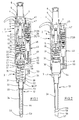
- the pipetting device according to FIGS. 1 and 2 has an elongated handle shaped Housing 1 with an upper housing part 2 and a lower housing part 3. Das Upper housing part 2 with all parts contained forms a drive device and the lower housing part 3 with all parts contained a displacement device.
- the upper housing part 2 has a screw top cover 4 at the top above an adjustment 5 out.
- the adjusting sleeve 5 is in the upper housing part 2 axially stored immovable and rotatable.
- a push button 6 is arranged, which still further upwards protrudes.
- the push button 6 is connected to a lifting rod 7, which in the upper housing part. 2 is passed through a spindle 8.
- the spindle 8 is in an internal thread 9 of a Screwed in the upper housing part 2 bearing body 10 is screwed.
- the spindle 8 has a rotatably connected to her driver 11 above.
- the Driver 11 has on the circumference two diametrically opposed radial projections 12.
- the radial projections 12 engage in - not shown - axially extending Grooves of the adjusting sleeve 5 a.
- the spindle 8 has at the bottom an end stop 13 in the form of radially outwardly projecting Ribs. In the position shown, the end stop 13 is a small piece below a shoulder 14 of the bearing body 10 with which it cooperates.
- the lifting rod 7 has a flange 15, which in the position shown at the bottom of the Spindle 8 is applied.
- a spring plate 16 is arranged, with a Collar 17 engages in the bearing body 10.
- the spring plate 16 has an axial bottom protruding, sleeve-shaped bearing portion 18 through which the lifting rod 7 passed is.
- the pipetting device on a spring, not shown, which the lifting rod 7 presses upward, so that the flange 15 at the bottom of the spindle. 8 is applied.
- a coil spring between flange 15 and spring plate 16th arranged.
- a coupling piece in the housing 19th attached at a distance below the spring plate 16 at a distance below the spring plate 16 at a distance below the spring plate 16 is a coupling piece in the housing 19th attached.
- This has several pockets inside 20. These have an axial over the Total length of the coupling piece 19 extended longitudinal groove 21. Furthermore, they have at the top End of the coupling piece 19 a over a small part of the circumference of the coupling piece 19 extended annular groove 22. This has at a distance from the upper end of the Coupling piece 19 below a ramp-like boundary wall, the starting from the longitudinal groove 21 increasingly to the upper end of the coupling piece 19th is approximated. Finally, the pockets 20 at the other end of the annular groove 22nd a short axial longitudinal groove portion 23 spaced at a distance from the upper end of the Coupling piece 19 ends in the coupling piece 19.
- spring 24 under bias arranged, which is designed as a helical spring.
- the adjusting sleeve 5 has on the circumference a sprocket 25 which is connected to a gear 26th cooperates, a counter 27 with several superimposed on an axis 28th arranged Zumblelwerkssonn 29 drives.
- the counter wheels 29 each have Numerals from 0 to 9, the lower Zählwerksrad 29 is driven by the gear 26.
- the arranged above it Zählwerksson 29 are further rotated by one digit, when the underlying Zählwerksrad 29 passes from 9 to 0.
- the lower housing part 3 can be detachably connected to the upper housing part 2. For this purpose points the lower housing part 3 on the jacket of an upper, cylindrical portion 30th a plurality of outwardly projecting projections or ribs 31, which extend in the axial direction of the cylindrical portion 30 extend.
- the lower housing part 3 has a plurality of below the cylindrical portion 30 conical sections 31 to 33 of different length and taper coming from the Drawing to emerge.
- the conical section 33 is down with a long, light conical projection 34 connected to attach a pipette tip. This one has turn down a short, more conical Aufsteckende 35.
- the lower housing part 3 houses a displacement device in the form of a Piston-cylinder unit 36. This has a arranged in the conical portion 32 Cylinder 37, in which a piston 38 dips. The piston 38 is above a piston rod 39 connected to a pressure piece 40. The piston 38 forms a displaceable Limitation of the cylinder 37.
- the lower housing part 3 has a piston holder 41, the the cylindrical portion 30 bridged above.
- the piston holder 41 has a top one central passage 42 through which a lower portion of the reciprocating piston 7 axially can be passed.
- a Lifting spring 43 arranged, which is designed as a helical spring. By the lifting spring 43 the piston 38 and the piston rod 39 are passed.
- the lifting spring 43 is biased and presses the pressure piece 40 against the piston holder 41, so that the piston 38 is pulled out of the cylinder 37 maximum.
- a connecting passage 44 passes through the boss 34 and connects the cylinder 37 with a muzzle in Aufsteckende 35.
- the pipetting device has a discharge device 45.
- the discharge device 45 has in the upper housing part 2 next to the knob 5, an operating button 46th
- the operating knob 46 is connected to a discharge rod 47 which is parallel to Lifting rod 7 passes through the upper housing part 2 therethrough.
- a transmission 48 is integrated in the discharge rod 47.
- the transmission 48 sets a axial actuating stroke of the actuating knob 46 in a smaller drive stroke with increased strength.
- Suitable transmissions 48 are described in EP 0 992 288 A, and Although generally in the general part of the description and especially in the figure description, which are incorporated by reference into the present application.
- the discharge rod 47 is connected via a further coil spring 49 in the upper housing part. 2 supported, so that the actuating button 46 is pressed into the starting position shown is in which he is pressed against the action of the other coil spring 49.
- the lower end of the discharge rod 47 protrudes into a receptacle 50 at the lower end of the Housing top 2 into it.
- the discharge device 45 has on the lower housing part 3 a discharge sleeve 51. This is on the cylindrical portion 30, the conical portion 32 and the projection 34th guided. Accordingly, the contour of the discharge sleeve 51 is the contours of the aforementioned Sections of the lower housing part 3 aligned.
- the ejection sleeve has 51 inside steps 52, 53, which limit the sliding of the discharge sleeve 51 upwards, by abutting against conical sections 31, 33 of the housing lower part 3.
- the pipetting device can be used as follows:
- the lifting rod engages 7 through the passage 42 through and lies with its lower end to the Pressure piece 40 on.
- a pipette tip 56 is clamped on the lower end of the projection 34.
- the pipette tip 56 has a lower tip opening 57 for receiving and dispensing of liquid.
- the push button 6 For pipetting the push button 6 is pressed down, so that the piston 38th Air displaced from the cylinder 37. Then the pipette tip 56 with its lower Tip opening 57 immersed in the liquid to be pipetted. After that, the Push button 6 released and the lifting rod 7 is under spring action in its starting position back. Similarly, the piston 38 returns under the action of the spring 43 in his starting position back. Here, the piston 38 sucks liquid through the lower tip opening 57 into the pipette tip 56.
- the lower tip opening 57 of the pipetting device becomes a discharge site aligned.
- the liquid contained in the pipette tip 56 is pressed in the push button 6, re-immersion of the piston 38 in the cylinder 37th and expelling air through the connecting channel 44 delivered. After releasing of the actuating knob 6 drive the lifting rod 7 and the piston 38 by spring force back to the starting position.
Landscapes
- Health & Medical Sciences (AREA)
- Clinical Laboratory Science (AREA)
- Chemical & Material Sciences (AREA)
- Chemical Kinetics & Catalysis (AREA)
- Devices For Use In Laboratory Experiments (AREA)
Applications Claiming Priority (2)
| Application Number | Priority Date | Filing Date | Title |
|---|---|---|---|
| DE102004003434A DE102004003434B4 (de) | 2004-01-21 | 2004-01-21 | Pipettiervorrichtung mit einer Verdrängungseinrichtung und einer damit lösbar verbundenen Antriebseinrichtung |
| DE102004003434 | 2004-01-21 |
Publications (2)
| Publication Number | Publication Date |
|---|---|
| EP1559480A1 true EP1559480A1 (fr) | 2005-08-03 |
| EP1559480B1 EP1559480B1 (fr) | 2013-05-01 |
Family
ID=34638748
Family Applications (1)
| Application Number | Title | Priority Date | Filing Date |
|---|---|---|---|
| EP05000211.2A Expired - Lifetime EP1559480B1 (fr) | 2004-01-21 | 2005-01-07 | Pipette avec mécanisme de déplacement fixé de façon détachable au mécanisme d'actionnement |
Country Status (3)
| Country | Link |
|---|---|
| US (1) | US7320260B2 (fr) |
| EP (1) | EP1559480B1 (fr) |
| DE (1) | DE102004003434B4 (fr) |
Cited By (5)
| Publication number | Priority date | Publication date | Assignee | Title |
|---|---|---|---|---|
| WO2006083695A3 (fr) * | 2005-01-28 | 2007-03-29 | Parker Hannifin Corp | Sonde d'echantillonnage, dispositif de prehension et interface de systemes de gestion d'echantillons de laboratoire |
| US8187535B2 (en) | 2004-06-14 | 2012-05-29 | Parker-Hannifin Corporation | Robotic handling system and method with independently operable detachable tools |
| US8192698B2 (en) | 2006-01-27 | 2012-06-05 | Parker-Hannifin Corporation | Sampling probe, gripper and interface for laboratory sample management systems |
| WO2014161857A1 (fr) * | 2013-04-04 | 2014-10-09 | Gilson Sas | Systeme de pipetage a commande et reglage de volume ameliores |
| US10639624B2 (en) | 2014-04-10 | 2020-05-05 | Gilson Sas | Multichannel pipetting system comprising two aspiration chambers that are imbricated in one another |
Families Citing this family (33)
| Publication number | Priority date | Publication date | Assignee | Title |
|---|---|---|---|---|
| US10610406B2 (en) * | 2004-07-21 | 2020-04-07 | Vanderbilt University | Drug delivery device and applications of same |
| EP1963837A1 (fr) * | 2005-12-05 | 2008-09-03 | Parker-Hannifin | Orifice d injection auto-nettoyant pour applications analytiques |
| US20090032065A1 (en) * | 2005-12-08 | 2009-02-05 | Bantz Daniel L | Syringe wash station for analytical applications |
| FR2980123B1 (fr) | 2011-09-19 | 2013-10-11 | Gilson Sas | Pipette a deplacement positif presentant une fonction d'ejection amelioree |
| US9027419B2 (en) | 2012-02-07 | 2015-05-12 | Eppendorf Ag | Pipette |
| DE102012002169B4 (de) | 2012-02-07 | 2017-02-09 | Eppendorf Ag | Pipette |
| DE102012003846B4 (de) | 2012-02-29 | 2014-12-11 | Eppendorf Ag | Pipette |
| US9044749B2 (en) | 2012-02-29 | 2015-06-02 | Eppendorf Ag | Pipette |
| US9358538B2 (en) | 2012-04-30 | 2016-06-07 | The Regents Of The University Of Michigan | High resolution pipette |
| PL2659978T3 (pl) | 2012-05-02 | 2017-11-30 | Eppendorf Ag | Pipeta z systemem blokowania |
| US9481903B2 (en) | 2013-03-13 | 2016-11-01 | Roche Molecular Systems, Inc. | Systems and methods for detection of cells using engineered transduction particles |
| BR112015023108A8 (pt) | 2013-03-13 | 2018-01-23 | Geneweave Biosciences Inc | sistema de acondicionamento de célula bacteriana, método para acondicionamento de uma molécula de ácido nucléico repórter, composição, método para detectar uma presença ou uma ausência de uma célula bacteriana em uma amostra, vetor, método para detectar um transcrito alvo em uma célula, método para detectar a presença de uma célula bacteriana em uma amostra e kit. |
| EP2972408B1 (fr) * | 2013-03-15 | 2019-04-17 | Douglas Scientific, LLC | Lavage par pipettes |
| FR3003643B1 (fr) * | 2013-03-25 | 2015-04-17 | Gilson Sas | Systeme de pipetage a deplacement positif presentant une fonction d'ejection amelioree |
| US9540675B2 (en) | 2013-10-29 | 2017-01-10 | GeneWeave Biosciences, Inc. | Reagent cartridge and methods for detection of cells |
| FR3012883B1 (fr) * | 2013-11-07 | 2015-12-25 | Gilson Sas | Systeme de pipetage a deplacement positif, presentant une conception facilitant la prehension du piston de l'ensemble capillaire-piston |
| US10016755B2 (en) * | 2015-01-08 | 2018-07-10 | Integra Biosciences Ag | Manual pipette with selectable plunger force |
| AU2016248939B2 (en) * | 2015-04-16 | 2018-03-29 | Integra Biosciences Ag | Volume adjustment for manual pipettor |
| FR3037825B1 (fr) * | 2015-06-24 | 2017-07-28 | Gilson Sas | Bouton de commande ameliore pour pipette de prelevement |
| US10351893B2 (en) | 2015-10-05 | 2019-07-16 | GeneWeave Biosciences, Inc. | Reagent cartridge for detection of cells |
| CH712010B1 (de) * | 2016-01-11 | 2021-10-15 | Integra Biosciences Ag | Pipette mit Abwurfmechanismus für Pipettenspitzen. |
| US10864515B2 (en) * | 2016-11-11 | 2020-12-15 | Walid Habbal | Automated pipette manipulation system |
| CN107941560B (zh) * | 2017-10-18 | 2020-04-14 | 山东中捷检测技术有限公司 | 一种具有密封性的食品检测提取装置 |
| CH714486A1 (de) | 2017-12-21 | 2019-06-28 | Integra Biosciences Ag | Probenverteilsystem und Verfahren zum Verteilen von Proben. |
| CN110161270B (zh) * | 2018-02-13 | 2024-01-12 | 杭州博拓生物科技股份有限公司 | 样本的收集和检测方法 |
| US10830672B2 (en) | 2018-02-13 | 2020-11-10 | Hangzhou Biotest Biotech Co., Ltd. | Apparatus for collecting liquid sample |
| WO2019215273A1 (fr) | 2018-05-09 | 2019-11-14 | F. Hoffmann-La Roche Ag | Dispositifs et procédés de détermination de la concentration de particules dans un échantillon |
| EP3831486A1 (fr) * | 2019-12-06 | 2021-06-09 | Eppendorf AG | Famille de pointes de pipette comprenant les pointes de pipette destinées à l'utilisation avec des pipettes d'une famille de pipettes et famille de pipettes comprenant les pipettes destinées à l'utilisation avec des pointes de pipette d'une famille de pointes de pipette |
| EP3851191A1 (fr) * | 2020-01-17 | 2021-07-21 | Eppendorf AG | Procédé de fonctionnement d'une pipette à course de piston, pipette à course de piston, appareil et système de traitement des données |
| EP3928868B1 (fr) * | 2020-06-22 | 2024-11-27 | Eppendorf SE | Pipette à utiliser avec une pointe de pipette ou une seringue comportant un piston et un cylindre |
| CN113976198A (zh) * | 2021-10-29 | 2022-01-28 | 美东汇成生命科技(昆山)有限公司 | 一种多功能移液吸头 |
| CN115608430B (zh) * | 2022-10-13 | 2024-11-15 | 中国航发北京航空材料研究院 | 一种移液参数调整方法、装置、设备及存储介质 |
| DE102024133874B3 (de) | 2024-11-19 | 2026-03-19 | Eppendorf Se | Einkanal-Unterteil für eine Pipette und Pipette mit einem Oberteil und einem Einkanal-Unterteil |
Citations (5)
| Publication number | Priority date | Publication date | Assignee | Title |
|---|---|---|---|---|
| US4099548A (en) * | 1976-08-25 | 1978-07-11 | Oxford Laboratories Inc. | Hand-held pipette for repetitively dispensing precise volumes of liquid |
| WO1991005609A1 (fr) * | 1989-10-20 | 1991-05-02 | Costar Corporation | Pipette |
| EP0428500A2 (fr) * | 1984-02-16 | 1991-05-22 | Rainin Instruments Co., Inc. | Procédé pour pipetter et/ou titrer des liquides utilisant une pipette autonome, automatique, tenue à la main |
| US5413006A (en) * | 1992-09-28 | 1995-05-09 | Gilson Medical Electronics (France) S.A. | Pipette for sampling and dispensing adjustable volumes of liquids |
| WO1998031465A1 (fr) * | 1997-01-17 | 1998-07-23 | Matrix Technologies Corporation | Dispositif de pipetage comportant un indicateur, et son mode d'utilisation |
Family Cites Families (14)
| Publication number | Priority date | Publication date | Assignee | Title |
|---|---|---|---|---|
| DE2017119A1 (en) * | 1970-04-10 | 1971-10-21 | Brand Fa Rudolf | Pipette suction cylinder with piston inter-lock |
| US3977574A (en) * | 1975-05-29 | 1976-08-31 | Bradley Scott Thomas | Dispensing pipette actuator system |
| DE2711124C2 (de) * | 1977-03-15 | 1979-05-10 | Labora Mannheim Gmbh Fuer Labortechnik, 6800 Mannheim | Handpipette |
| GB2161398A (en) * | 1984-07-11 | 1986-01-15 | Scient Supplies M B | Pipette |
| GB8614899D0 (en) * | 1986-06-19 | 1986-07-23 | Grace W R & Co | Burette |
| JP2701900B2 (ja) * | 1988-12-20 | 1998-01-21 | 株式会社ニチリョー | マルチピペット |
| US5104624A (en) * | 1989-10-20 | 1992-04-14 | Costar Corporation | Pipetter |
| US5700959A (en) * | 1995-07-14 | 1997-12-23 | Rainin Instrument Co., Inc. | Manual pipette with magnet assist |
| US5906795A (en) * | 1996-04-08 | 1999-05-25 | Sanyo Electric Co., Ltd. | Pipetting apparatus |
| US6499363B1 (en) * | 1997-12-12 | 2002-12-31 | The Sailor Pen Co., Ltd. | Tip for pipette and pipette with the same |
| DE19845950C1 (de) * | 1998-10-06 | 2000-03-23 | Eppendorf Geraetebau Netheler | Pipettiersystem mit einer Pipettiervorrichtung und mindestens einer daran lösbar befestigten Pipettenspitze |
| US6428750B1 (en) * | 2000-02-17 | 2002-08-06 | Rainin Instrument, Llc | Volume adjustable manual pipette with quick set volume adjustment |
| DE10040849A1 (de) * | 2000-08-21 | 2002-03-21 | Mwg Biotech Ag | Pipettierkopf für einen Roboter mit mehreren Pipettierspitzen |
| FI20010972A0 (fi) * | 2001-05-09 | 2001-05-09 | Thermo Labsystems Oy | Kärkisäiliöpipetti |
-
2004
- 2004-01-21 DE DE102004003434A patent/DE102004003434B4/de not_active Expired - Lifetime
-
2005
- 2005-01-07 EP EP05000211.2A patent/EP1559480B1/fr not_active Expired - Lifetime
- 2005-01-20 US US11/038,799 patent/US7320260B2/en not_active Expired - Lifetime
Patent Citations (5)
| Publication number | Priority date | Publication date | Assignee | Title |
|---|---|---|---|---|
| US4099548A (en) * | 1976-08-25 | 1978-07-11 | Oxford Laboratories Inc. | Hand-held pipette for repetitively dispensing precise volumes of liquid |
| EP0428500A2 (fr) * | 1984-02-16 | 1991-05-22 | Rainin Instruments Co., Inc. | Procédé pour pipetter et/ou titrer des liquides utilisant une pipette autonome, automatique, tenue à la main |
| WO1991005609A1 (fr) * | 1989-10-20 | 1991-05-02 | Costar Corporation | Pipette |
| US5413006A (en) * | 1992-09-28 | 1995-05-09 | Gilson Medical Electronics (France) S.A. | Pipette for sampling and dispensing adjustable volumes of liquids |
| WO1998031465A1 (fr) * | 1997-01-17 | 1998-07-23 | Matrix Technologies Corporation | Dispositif de pipetage comportant un indicateur, et son mode d'utilisation |
Cited By (8)
| Publication number | Priority date | Publication date | Assignee | Title |
|---|---|---|---|---|
| US8187535B2 (en) | 2004-06-14 | 2012-05-29 | Parker-Hannifin Corporation | Robotic handling system and method with independently operable detachable tools |
| WO2006083695A3 (fr) * | 2005-01-28 | 2007-03-29 | Parker Hannifin Corp | Sonde d'echantillonnage, dispositif de prehension et interface de systemes de gestion d'echantillons de laboratoire |
| US8057756B2 (en) | 2005-01-28 | 2011-11-15 | Parker-Hannifin Corporation | Sampling probe, gripper and interface for laboratory sample management systems |
| US8192698B2 (en) | 2006-01-27 | 2012-06-05 | Parker-Hannifin Corporation | Sampling probe, gripper and interface for laboratory sample management systems |
| WO2014161857A1 (fr) * | 2013-04-04 | 2014-10-09 | Gilson Sas | Systeme de pipetage a commande et reglage de volume ameliores |
| FR3004258A1 (fr) * | 2013-04-04 | 2014-10-10 | Gilson Sas | Systeme de pipetage a commande et reglage de volume ameliores |
| US9649628B2 (en) | 2013-04-04 | 2017-05-16 | Gilson Sas | Pipetting system with improved control and volume adjustment |
| US10639624B2 (en) | 2014-04-10 | 2020-05-05 | Gilson Sas | Multichannel pipetting system comprising two aspiration chambers that are imbricated in one another |
Also Published As
| Publication number | Publication date |
|---|---|
| DE102004003434B4 (de) | 2006-06-08 |
| US20050155438A1 (en) | 2005-07-21 |
| DE102004003434A1 (de) | 2005-08-25 |
| EP1559480B1 (fr) | 2013-05-01 |
| US7320260B2 (en) | 2008-01-22 |
Similar Documents
| Publication | Publication Date | Title |
|---|---|---|
| EP1559480B1 (fr) | Pipette avec mécanisme de déplacement fixé de façon détachable au mécanisme d'actionnement | |
| EP1557222B1 (fr) | Pipette avec éjecteur d'embouts de pipette | |
| EP2633913B1 (fr) | Dispositif de pipetage et dispositif de pipetage multi-canal | |
| EP3478418B1 (fr) | Tête de dosage, dispositif de dosage comprenant une tête de dosage et procédé de dosage au moyen d'une tête de dosage | |
| EP3680016B1 (fr) | Pipette destinée à une utilisation avec une pointe de pipette | |
| EP3479129B1 (fr) | Tête de dosage, dispositif de dosage comprenant une tête de dosage et procédé de dosage au moyen d'une tête de dosage | |
| EP1407861B1 (fr) | Outil de préhension, outil de dosage et support d'outil pour automate de laboratoire | |
| EP2425896B1 (fr) | Seringue pour l'utilisation à l'aide d'un dispositif de dosage | |
| EP2659978B1 (fr) | Pipette avec systeme de blockage | |
| EP2033712A1 (fr) | Pipette | |
| DE102005023203A1 (de) | Pipette | |
| EP2735369A1 (fr) | Pipette multi-canal | |
| EP2633915A2 (fr) | Pipette | |
| EP1759768B1 (fr) | Pipette | |
| EP1598113B1 (fr) | Pipette | |
| EP3793738A1 (fr) | Tête de pipetage, dispositif de pipetage comprenant une tête de pipetage et procédé de pipetage au moyen d'une tête de pipetage | |
| DE19708151C2 (de) | Pipettiervorrichtung | |
| DE102006031460B4 (de) | Pipettiervorrichtung | |
| EP3680017B1 (fr) | Pipette destinée à une utilisation avec une pointe de pipette | |
| EP2732877A1 (fr) | Pipette à pistons élévateurs dotés d'une unité de refoulement interchangeable | |
| EP2626134B1 (fr) | Pipette | |
| EP3189897A1 (fr) | Mécanisme d'éjection pour points de pipette | |
| EP3778028A1 (fr) | Pipette à volume de dosage réglable | |
| EP2210667B1 (fr) | Dispositif de dosage avec éjecteur de pointe | |
| DE10355914B3 (de) | Pipettiervorrichtung mit einer Abwurfeinrichtung für Pipettenspitzen |
Legal Events
| Date | Code | Title | Description |
|---|---|---|---|
| PUAI | Public reference made under article 153(3) epc to a published international application that has entered the european phase |
Free format text: ORIGINAL CODE: 0009012 |
|
| AK | Designated contracting states |
Kind code of ref document: A1 Designated state(s): AT BE BG CH CY CZ DE DK EE ES FI FR GB GR HU IE IS IT LI LT LU MC NL PL PT RO SE SI SK TR |
|
| AX | Request for extension of the european patent |
Extension state: AL BA HR LV MK YU |
|
| 17P | Request for examination filed |
Effective date: 20050630 |
|
| AKX | Designation fees paid |
Designated state(s): DE FR GB IT |
|
| 17Q | First examination report despatched |
Effective date: 20071017 |
|
| GRAP | Despatch of communication of intention to grant a patent |
Free format text: ORIGINAL CODE: EPIDOSNIGR1 |
|
| GRAS | Grant fee paid |
Free format text: ORIGINAL CODE: EPIDOSNIGR3 |
|
| GRAA | (expected) grant |
Free format text: ORIGINAL CODE: 0009210 |
|
| AK | Designated contracting states |
Kind code of ref document: B1 Designated state(s): DE FR GB IT |
|
| REG | Reference to a national code |
Ref country code: GB Ref legal event code: FG4D Free format text: NOT ENGLISH |
|
| REG | Reference to a national code |
Ref country code: DE Ref legal event code: R096 Ref document number: 502005013669 Country of ref document: DE Effective date: 20130627 |
|
| PLBE | No opposition filed within time limit |
Free format text: ORIGINAL CODE: 0009261 |
|
| STAA | Information on the status of an ep patent application or granted ep patent |
Free format text: STATUS: NO OPPOSITION FILED WITHIN TIME LIMIT |
|
| 26N | No opposition filed |
Effective date: 20140204 |
|
| REG | Reference to a national code |
Ref country code: DE Ref legal event code: R097 Ref document number: 502005013669 Country of ref document: DE Effective date: 20140204 |
|
| REG | Reference to a national code |
Ref country code: FR Ref legal event code: PLFP Year of fee payment: 12 |
|
| REG | Reference to a national code |
Ref country code: FR Ref legal event code: PLFP Year of fee payment: 13 |
|
| REG | Reference to a national code |
Ref country code: FR Ref legal event code: PLFP Year of fee payment: 14 |
|
| REG | Reference to a national code |
Ref country code: FR Ref legal event code: PLFP Year of fee payment: 19 |
|
| REG | Reference to a national code |
Ref country code: DE Ref legal event code: R081 Ref document number: 502005013669 Country of ref document: DE Owner name: EPPENDORF SE, DE Free format text: FORMER OWNER: EPPENDORF AG, 22339 HAMBURG, DE |
|
| P01 | Opt-out of the competence of the unified patent court (upc) registered |
Effective date: 20230527 |
|
| PGFP | Annual fee paid to national office [announced via postgrant information from national office to epo] |
Ref country code: DE Payment date: 20240119 Year of fee payment: 20 Ref country code: GB Payment date: 20240123 Year of fee payment: 20 |
|
| PGFP | Annual fee paid to national office [announced via postgrant information from national office to epo] |
Ref country code: IT Payment date: 20240122 Year of fee payment: 20 Ref country code: FR Payment date: 20240124 Year of fee payment: 20 |
|
| REG | Reference to a national code |
Ref country code: DE Ref legal event code: R071 Ref document number: 502005013669 Country of ref document: DE |
|
| REG | Reference to a national code |
Ref country code: GB Ref legal event code: PE20 Expiry date: 20250106 |
|
| PG25 | Lapsed in a contracting state [announced via postgrant information from national office to epo] |
Ref country code: GB Free format text: LAPSE BECAUSE OF EXPIRATION OF PROTECTION Effective date: 20250106 |