EP0477571B1 - Appareil diagnostique par ultrasons pour produire une image de qualité supérieure par correction de la distorsion de phase des impulsions d'ultrasons - Google Patents
Appareil diagnostique par ultrasons pour produire une image de qualité supérieure par correction de la distorsion de phase des impulsions d'ultrasons Download PDFInfo
- Publication number
- EP0477571B1 EP0477571B1 EP91114462A EP91114462A EP0477571B1 EP 0477571 B1 EP0477571 B1 EP 0477571B1 EP 91114462 A EP91114462 A EP 91114462A EP 91114462 A EP91114462 A EP 91114462A EP 0477571 B1 EP0477571 B1 EP 0477571B1
- Authority
- EP
- European Patent Office
- Prior art keywords
- correcting
- delay
- phase
- diagnostic apparatus
- echo signals
- Prior art date
- Legal status (The legal status is an assumption and is not a legal conclusion. Google has not performed a legal analysis and makes no representation as to the accuracy of the status listed.)
- Expired - Lifetime
Links
Images


Classifications
-
- G—PHYSICS
- G01—MEASURING; TESTING
- G01S—RADIO DIRECTION-FINDING; RADIO NAVIGATION; DETERMINING DISTANCE OR VELOCITY BY USE OF RADIO WAVES; LOCATING OR PRESENCE-DETECTING BY USE OF THE REFLECTION OR RERADIATION OF RADIO WAVES; ANALOGOUS ARRANGEMENTS USING OTHER WAVES
- G01S7/00—Details of systems according to groups G01S13/00, G01S15/00, G01S17/00
- G01S7/52—Details of systems according to groups G01S13/00, G01S15/00, G01S17/00 of systems according to group G01S15/00
- G01S7/52017—Details of systems according to groups G01S13/00, G01S15/00, G01S17/00 of systems according to group G01S15/00 particularly adapted to short-range imaging
- G01S7/52085—Details related to the ultrasound signal acquisition, e.g. scan sequences
-
- A—HUMAN NECESSITIES
- A61—MEDICAL OR VETERINARY SCIENCE; HYGIENE
- A61B—DIAGNOSIS; SURGERY; IDENTIFICATION
- A61B8/00—Diagnosis using ultrasonic, sonic or infrasonic waves
- A61B8/13—Tomography
- A61B8/14—Echo-tomography
-
- G—PHYSICS
- G01—MEASURING; TESTING
- G01S—RADIO DIRECTION-FINDING; RADIO NAVIGATION; DETERMINING DISTANCE OR VELOCITY BY USE OF RADIO WAVES; LOCATING OR PRESENCE-DETECTING BY USE OF THE REFLECTION OR RERADIATION OF RADIO WAVES; ANALOGOUS ARRANGEMENTS USING OTHER WAVES
- G01S7/00—Details of systems according to groups G01S13/00, G01S15/00, G01S17/00
- G01S7/52—Details of systems according to groups G01S13/00, G01S15/00, G01S17/00 of systems according to group G01S15/00
- G01S7/52017—Details of systems according to groups G01S13/00, G01S15/00, G01S17/00 of systems according to group G01S15/00 particularly adapted to short-range imaging
- G01S7/52023—Details of receivers
- G01S7/52025—Details of receivers for pulse systems
- G01S7/52026—Extracting wanted echo signals
-
- G—PHYSICS
- G01—MEASURING; TESTING
- G01S—RADIO DIRECTION-FINDING; RADIO NAVIGATION; DETERMINING DISTANCE OR VELOCITY BY USE OF RADIO WAVES; LOCATING OR PRESENCE-DETECTING BY USE OF THE REFLECTION OR RERADIATION OF RADIO WAVES; ANALOGOUS ARRANGEMENTS USING OTHER WAVES
- G01S7/00—Details of systems according to groups G01S13/00, G01S15/00, G01S17/00
- G01S7/52—Details of systems according to groups G01S13/00, G01S15/00, G01S17/00 of systems according to group G01S15/00
- G01S7/52017—Details of systems according to groups G01S13/00, G01S15/00, G01S17/00 of systems according to group G01S15/00 particularly adapted to short-range imaging
- G01S7/52046—Techniques for image enhancement involving transmitter or receiver
- G01S7/52049—Techniques for image enhancement involving transmitter or receiver using correction of medium-induced phase aberration
Definitions
- the present invention generally relates to an ultrasonic diagnostic apparatus according to the pre-characterizing part of claim 1. Such apparatus is used to acquiring ultrasonic images of a biological body. More specifically, the present invention is directed to an ultrasonic diagnostic apparatus capable of improving image qualities of the acquired ultrasonic images with respect to unequal portions within the biological body based upon fluctuations in arrival times of the echo signals.
- the echo signals derived from a plurality of transducer elements arranged in an array form are detected by a guadrature-phase detecting means so as to obtain quadrature and in-phase signal components as phase data against a reference signal.
- Data on delay times which are determined based on geometrical positional information with respect to the respective transducer elements, are electrically given to the echo signals reflected from interiors of a biological body.
- Energizing signals are used to transmit ultrasonic pulses from the transducer elements toward the biological body.
- a focal point of the echo signals is defined by the known in-phase additional process so as to obtain a desirable ultrasonic image of the biological body.
- the focal point is scanned under electronic scanning control, for instance, in a plane form. More specifically, while several tens to several hundreds of rasters are transmitted/received, a "B-mode" ultrasonic image is obtained in an image constructive unit.
- non-reflection (non-echo) portions within a biological body such as cholecystics and blood vessels, from which ultrasonic beams are not reflected as the echo pulses. If a focal point to be ultrasonic-imaged is selected at cholecystics, no reflection signal (echo signal) is obtained therefrom, so that no delay correction value of this focused cholecystics portion is calculated. Accordingly, there is a third problem that reflection signals suitable for ultrasonic measurements are not always obtained.
- the object of the present invention is to provide such an ultrasonic diagnostic apparatus capable of improving ultrasonic image quality in a real time, wherein the apparatus is capable of forming a focal point within a biological body without any phase shift. This object is achieved by the features of claim 1.
- the present invention provides an ultrasonic diagnostic apparatus capable of correctly evaluating echo signals reflected from various biological conditions of a biological body.
- the apparatus is capable of precisely correcting delay amounts of transmitting/received signals, namely, fluctuation contained in signal propagation time.
- a phase detecting means processes reception signals (i.e., echo signals) received by a plurality of transducer elements so as to detect phases of the respective echo signals
- a converting means will convert these phase data into corresponding delay time data.
- a correcting means corrects a predetermined delay time based on the converted delay time data, whereby since the corrected delay times corresponding to propagation mediums of a biological body under medical examination are electronically applied to both the energizing signals and echo (reflection) signals for the plural transducer elements, a focal point can be formed with a slight phase shift.
- phase correcting means corrects these phase discontinuities to obtain phase continuities.
- the correct phase data having no error caused by these discontinuities may be inputted into the converting means.
- a control means controls data write/read-operations to a plurality of memories, and also controls such that the delay time data obtained by way of the predetermined calculating process are applied to both the energizing signals and echo signals so as to newly acquire ultrasonic images of the biological body, whereby a focal point with a less phase shift can be formed in a real time.
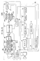
- FIG. 5 there is shown an ultrasonic diagnostic apparatus 1000 according to a first preferred embodiment of the present invention, that is realized by utilizing the above-described first basic idea of the present invention.
- the first ultrasonic diagnostic apparatus 1000 mainly comprises an ultrasonic probe 2 having a plurality of transducer elements V arranged in an array form (as shown in Fig. 1); a multiplexer 3 for sequentially energizing the plural transducer elements V; a display system 10 for displaying an ultrasonic image of a biological body under medical examination (not shown in detail) in response to echo signals derived from the transducer elements V; and a signal correction system 20 for correcting delay times of energizing signals and echo (reception) signals of the transducer elements.
- the display unit 10 includes an energizing signal generating section 11 for producing the energizing signals having a predetermined central frequency, e.g., 3MHz with a narrow bandwidth, and also a reference signal "S 1 " to be supplied to the signal correction system 10; a reception delay circuit 12 for applying a predetermined delay time to the echo signals; an adder 15 for performing an addition process with respect to these signals; and a delay control section 13 having a delay time memory (not shown in detail), for applying delay times to the above-described energizing signal generating circuit 11 and reception delay circuit 12; and furthermore a display section 14 equipped with a television monitor (not shown in detail) for displaying ultrasonic images of the biological body thereon.
- a predetermined central frequency e.g., 3MHz with a narrow bandwidth
- S 1 reference signal
- predetermined delay time data produced based on geometric positional information about the tansducer elements V are stored, which are supplied to the signal correction system 20 in order that the corrected delay times are produced and used in the energizing-signal generating section 11 and reception delay circuit 12.
- a total number of these transducer elements V is selected to be “m” ("m” being an integer greater than 2) in this preferred embodiment, and therefore "m” pieces of echo signals are received by the transducer elements V.
- the signal correction system 20 includes a phase detecting section 30 for detecting phases of the received echo signals by processing the echo signals received from the probe 2 via the multiplexer 3; a phase correcting section 21 for correcting discontinuities contained in the phase data detected by the phase detecting unit 30; a storage unit 22 for storing therein continuous phase data which are obtained from the phase correcting unit 21; and a converting section 23 for performing one process to convert the data and the other process to interpolate the data.
- the signal correction system 20 further includes a central processing unit 24 which may function as a correction means for correcting the delay time data stored in the delay time memory of the delay control section 13 based on the delay time data converted by the converting section 23; and a 90°-phase shifter 25.
- phase detecting sections 30-1 and 30-2 are employed so as to detect phase information as ultrasonic Doppler information, which is well known in the art.
- One phase detecting section 30-1 is constructed of a first mixer 32A, a second mixer 32B, a first low-pass filter 35A, a second low-pass filter 35B, a first integrator 35A, a second integrator 35B, and an arc tangent (tan -1 ) circuit 36.
- the first mixer 32A mixes a signal "S" derived from the reception delay circuit 12 with a reference signal “(cos ⁇ t) S 1 " that is synchronized with the energizing signal outputted from the energizing signal generating section 11.
- the second mixer 32A mixes the above-described signal "S" derived from the reception delay circuit 12 with a signal (sin ⁇ t) S 2 which is produced by phase-shifting the reference signal S 1 from the energizing signal generating section 11 in the 90°-phase shifter 25 by 90°.
- These signal phase correcting sections 30-1 and 30-2 perform the above-described signal process by inputting therein the reception signals "S" with respect to all rasters or every several rasters.
- the angular frequency " ⁇ " of two reference signals (cos ⁇ t) S 1 and (sin ⁇ t) S 2 supplied from the energizing signal generating section 11 to the first and second mixers 32A and 32B are selected to be one of frequencies of the reception (echo) signal "S".
- the function of the first and second integrators 35A and 35B is to integrate the echo signals, thereby obtaining an averaged phase within a certain range of the reception signals.
- Z k (t) A k (t) • [ cos (2 ⁇ t+ ⁇ k ) + cos ( ⁇ k ) ] + j ⁇ A k (t) • [ sin ( ⁇ k ) - sin (2 ⁇ t+ ⁇ k )] ⁇
- phase correcting section 21 As previously explained, "n" pieces of phase data ( ⁇ 1 to ⁇ n ) are inputted into the phase correcting section 21 within a phase range from “- ⁇ ” to "+ ⁇ ", as shown in Fig. 6.
- the function of this phase correcting section 21 is to couple discontinuities f (f 1 , f 2 ) with each other contained in the phase distribution data under control of CPU 24. As shown in Fig. 6, these discontinuities f (f 1 , f 2 ) are coupled with each other and then are obtained as the continuous phase distribution data as shown in Fig. 7.
- the continuous phase distribution data are supplied to the respective storage sections 22 (22a to 22c) every image constructive unit (data constituting one image), in the following referred to as image unit.
- the storage section 22 employs three RAMs 22a to 22c. Under control of CPU 24, changing switches "A", "B” and “C” are operated every one image unit in order that both the phase data from the phase correcting section 21, and the delay time data which has been converted and interpolated by the converting section 23 are sequentially written into these RAMs 22a to 22c.
- the function of the converting unit 23 is to convert the phase data obtained every all rasters, or several rasters into delay time data, and also to interpolate the delay time data with respect to the skipped (or not processed) several rasters while acquiring the phase data every several rasters. Under control of CPU 24, the predetermined delay time data stored in the delay time memory of the delay time control unit 13, is corrected every one image unit based on the converted/interpolated delay time data.
- an ultrasonic image of the biological body is acquired by the first ultrasonic diagnostic apparatus 1000, for instance, in a B-mode under control of CPU 24.
- the delay control section 13 delay-controls the energizing signal generating section 11 and adder 15 based on the predetermined delay time data stored in the delay time memory employed therein.
- the probe 2 performs B-mode scanning operation with respect to first image unit under control of CPU 24. Accordingly, a B-mode ultrasonic image of the first image unit is displayed on the TV monitor of the display section 14 employed in the display system 10. It should be noted that at this stage, since the predetermined delay time data have not yet been corrected in accordance with the propagation mediums within the biological body, the sufficiently focused focal point is formed, resulting in lowered space resolution.
- the signal correction system 20 calculates delay times for correction purposes in response to the reception signal "S" from the multiplexer 3 and therefore corrects the predetermined delay time data which have been stored in the delay time memory of the delay control section 13 based on the calculated correcting delay times, thereby to obtain desirable delay times corrected by taking account of the propagation mediums constructing the biological body.
- Fig. 8 represents contents of the signal process operations and of the memory RAMs 22a to 22c with respect to the image unit.
- symbol “W” indicates write operation of data into RAMs 22a to 22c
- symbol “R” denotes read operation of data from RAMs 22a to 22c
- reference numerals written with these symbols “W” and “R” indicate numbers of the image unit
- symbols “A”, “B”, “C” represent switching operations of the switches A to C (see Fig. 5).
- the received (echo) signals are phase-detected by the phase detective section 30 and then the discontinuities (f 1 , f 2 ) contained in the phase-detected echo signals are corrected by the phase correcting section 21 based upon the phase detected information, and the resultant image data are represented as "W-1-A".
- the image data "W-1-A” are written into RAM 22a while the switch "A” is actuated.
- the converting section 23 receives the phase-corrected data "R/W-1-B" which have been previously written into the RAM 22a and acquired based on the phase-corrected data on the first image constructive unit. Then, the phase-detected data "R/W-1-B” are converted into the desirable delay time data by this converting section 23, which are written into the RAM 22a.
- the phase-corrected data on the second image unit are represented as "W-2-A", which are derived from the phase correcting section 21, and written into RAM 22b by operating the switch "A".
- the delay control section 13 reads out the delay time data on the first image unit stored in RAM 22a, as indicated by "R-1-C", and performs the correction when the transmission/reception delay operations are actually performed. Thereafter, the phase-corrected data on the second image unit stored into RAM 22b, as indicated as "R/W-2-B", are acquired and converted into the corresponding delay time data in the converting section 23. Also, these phase-corrected data are written into RAM 22b, and the phase-corrected data denoted by "W-3-A" are written from the phase correcting section 21 into RAM 22c by operating the switch "A".
- the desirable focal point with the less phase shift can be formed based upon this B-mode image scanning operation and therefore the B-mode images can be formed with the improved spatial resolution and contrast resolution on the display section 14.
- the image data on the third and subsequent image units are similarly processed and the resultant processed image data are written/read from RAM 22a to 22c.
- the focal point with the small phase shift can be formed and the ultrasonic images with the better image quality can be obtained.
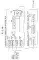
- Fig. 9 is a schematic block diagram of an ultrasonic diagnostic apparatus 2000 according to a second preferred embodiment of the present invention. It should be noted that the same reference numerals shown in Fig. 5 will be employed as those for denoting the same circuit elements shown in the following figures. Also, this second ultrasonic diagnostic apparatus 2000 is realized based on the first basic idea of the present invention.
- a major different construction of the second ultrasonic diagnostic apparatus 2000 from the first ultrasonic diagnostic apparatus 1000 is to newly employ a phase detecting section 130 and a phase correcting section 121 of a signal correcting system 120.
- the phase detecting section 130 corresponds to the phase detecting section 30 of the first ultrasonic diagnostic apparatus 1000 from which the first and second integrators 35A and 35B are omitted. Since the integrators 35A and 35B are omitted from this phase detecting section 130, the function of this phase detecting section 130 is to obtain instantaneous phase data at time instants "t 1 " to "t n " as shown in Fig. 10. This drawing indicates a discontinuity "f" occurring at the respective time instants "t 1 " to "T n " along the array direction of the transducer elements V.
- the above-described phase correcting section 121 is arranged by a discontinuity correction section 121A and a temporal direction averaging section 121B.
- the discontinuity correction section 121A corrects the discontinuities of the phase data (see Fig. 11) every time instants "t 1 " to "t n ".
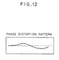
- the temporal direction averaging section 121B averages the phase data at the respective time instants "t 1 " to "t n " the discontinuities of which have been corrected, and obtains such a phase distortion pattern as shown in Fig. 12.
- discontinuity correcting section 121A The above-described discontinuity operation by the discontinuity correcting section 121A will now be described more in detail with reference to Figs. 13 to 16.
- the major operation of this discontinuity correcting section 121A is such that after the discontinuity point "f" has been searched, a bias value is applied to the phase data at this discontinuity point "f" so as to obtain continuous phase data without any discontinuities.
- a starting point "f 10 " of the calculating process for the equation (5) is selected. It should be understood that although an end point at the left side of Fig. 13 is selected to be “f 10 ", any other points may be selected to be this end point. Also, it should be noted that a bias value at this starting point “f 10 " is selected to be “O”.
- the phase difference calculation is carried out is such a manner that a phase difference " ⁇ " is first calculated between the starting point "f 10 " and the adjacent point "f 10-2 ", and subsequently, another phase difference ⁇ is calculated between this point "f 10-2 " and the adjacent point "f 10-3 ".
- the calculation results become discontinuity points f 13 and f 14 ; f 17 and f 18 ; f 19 and f 20 ; f 21 and f 22 , which suddenly change from a negative to a positive, the calculation results become +2 ⁇ approximately.
- a comparison is made between the calculation results shown in Fig. 15 and a threshold level " ⁇ ". That is, based on the following inequality (7), assuming now that the threshold level " ⁇ " is selected to be 1.9 ⁇ , a bias value of ⁇ 2 ⁇ is given to the phase difference ⁇ ⁇ 1.9 ⁇ ; a bias value of + 2 ⁇ is given to the phase difference ⁇ ⁇ 0 (namely "negative") and a bias value of - 2 ⁇ is given to the phase difference ⁇ > 0 (namely "positive”).
- Fig. 16 is a schematic block diagram for showing an internal arrangement of the discontinuity correcting section 121A and temporal direction averaging section 121B.
- the phase data are supplied from the phase detecting sections 130-1 and 130-2 and stored in corresponding memories 122-1 through 122-n. These phase data stored in the memories 122-1 to 122-n are selectively and successively read and supplied to both a subtracter 124 and a bias applying circuit 125 by operating a switch 123.
- the subtracter 124 successively subtracts the phase data on the adjacent echo signals from each other to obtain the phase differences ⁇ .
- the resultant phase differences ⁇ are supplied to a bias judging circuit 126.
- the bias judging circuit 126 judges the phase data based upon the phase difference data ⁇ and the threshold value " ⁇ " so as to determine a proper bias value. As a result of this judgement, the bias applying circuit 125 applies the proper bias value such as +2 ⁇ to the phase data, whereby the discontinuity point contained in this phase data can be corrected, resulting in the continuous phase data.
- the continuous phase data are successively obtained from the discontinuity correcting section 121A and thereafter furnished to a first memory 127A of the temporal direction averaging section 121B.
- a plurality of continuous phase data are averaged in an averaging circuit 128 thereby to obtain the final continuous phase data from which the discontinuities have been eliminated (see Fig. 15).
- the second ultrasonic diagnostic apparatus 2000 has such a particular advantage that even when the phase data outputted from the phase detecting section 130 contains the discontinuities "f", the discontinuities can be surely corrected by the phase correcting section 121, in addition to the previous advantages of the first ultrasonic diagnostic apparatus 1000. As a consequence, there is less calculation error caused by the discontinuities contained in the phase data. Since the focal point of the ultrasonic pulses can be formed without any phase shifts contained therein, the ultrasonic images of the biological body with the better image quality can be stably obtained.
- the third ultrasonic diagnostic apparatus 3000 employs only a different circuit element, as compared with the first ultrasonic diagnostic apparatus 1000. That is, a second multiplexer 221 and a converting section 223 are newly employed.
- the second multiplexer 221 successively transfers the phase data ⁇ 1 to ⁇ n outputted from the phase detecting sections 30-1 and 30-2, via the switch to the storage section 22 under control of CPU 24.
- the converting section 225 owns the similar function to the phase correcting section 121 of the second ultrasonic diagnostic apparatus 2000 shown in Fig. 9. That is, this converting section 223 performs such a phase correcting process similar to that of the phase correcting section 121; such a converting process that the phase data acquired for all rasters or every several rasters are converted into delay time data; and also such a delay time data interpolation that the data interpolation is performed for the delay time data on the skipped several rasters while the phase data are acquired every several rasters.
- the third ultrasonic diagnostic apparatus 3000 has the similar effects and advantages as those of the second ultrasonic diagnostic apparatus 2000.
Landscapes
- Engineering & Computer Science (AREA)
- Physics & Mathematics (AREA)
- Computer Networks & Wireless Communication (AREA)
- General Physics & Mathematics (AREA)
- Radar, Positioning & Navigation (AREA)
- Remote Sensing (AREA)
- Health & Medical Sciences (AREA)
- Life Sciences & Earth Sciences (AREA)
- Pathology (AREA)
- Molecular Biology (AREA)
- Biophysics (AREA)
- Radiology & Medical Imaging (AREA)
- Biomedical Technology (AREA)
- Heart & Thoracic Surgery (AREA)
- Medical Informatics (AREA)
- Nuclear Medicine, Radiotherapy & Molecular Imaging (AREA)
- Surgery (AREA)
- Animal Behavior & Ethology (AREA)
- General Health & Medical Sciences (AREA)
- Public Health (AREA)
- Veterinary Medicine (AREA)
- Ultra Sonic Daignosis Equipment (AREA)
- Investigating Or Analyzing Materials By The Use Of Ultrasonic Waves (AREA)
Claims (5)
- Appareil de diagnostic à ultrasons (2000), comprenant :caractérisé par :des moyens formant transducteurs à ultrasons (2) ayant une pluralité d'éléments de transducteurs à ultrasons (V) pour transmettre des impulsions ultrasonores vers un objet en cours d'examen médical en réponse à des signaux d'excitation, et pour recevoir des échos de ces impulsions afin de produire des signaux d'écho (S),des moyens de commande de retard (11, 12, 13) qui supportent les signaux d'excitation et les signaux d'écho (S) avec des temps de retard déterminés en accord avec les informations relatives à la position géométrique des éléments transducteurs,des moyens de calcul de valeur de correction de temps de retard (23) qui calculent des valeurs de correction du temps de retard, etdes moyens de correction de temps de retard (24) qui corrigent le temps de retard dans lesdits moyens de commande de retard (13) avec les valeurs de correction de temps de retard pour former un point focal sans décalage de phase,des moyens de détection de quadrature de phase (25, 130) pour injecter les signaux d'écho dérivés depuis les moyens formant transducteurs (2) et des signaux de référence (S1, S2), et pour obtenir des données de phase () en se basant sur une composante de signal de quadrature et sur une composante de signal en phase contenues dans les signaux d'écho,des moyens de correction de discontinuité (121A) pour corriger les données de phase de telle manière que les points de discontinuité (f1, f2, ..., fn) contenus dans les données de phase sont recherchés et, en réponse aux points de discontinuité identifiés, les discontinuités correspondantes dans les données de phase sont supprimées en ajoutant une valeur de polarisation, sous la forme +/- 2π de manière à fournir des données de phase continues,des moyens de moyennage de direction temporaire (121B) pour moyenner les données de façon continue, etlesdits moyens de calcul de valeur de correction de retard (23) calculant les valeurs de correction de retard en se basant sur les données de phase continue moyennées.
- Appareil de diagnostic à ultrasons (2000) selon la revendication 1, dans lequel lesdits moyens de calcul de valeurs de correction de retard (23) exécutent en outre un processus d'interpolation basé sur les signaux d'écho réellement reçus tandis que seulement un nombre prédéterminé d'éléments transducteurs (V ; 43) sont excités par les signaux d'excitation, grâce à quoi on obtient les signaux d'écho par rapport à tous les éléments transducteurs.
- Appareil de diagnostic à ultrasons (2000) selon l'une ou l'autre des revendications 1 et 2, dans lequel lesdits moyens de correction de discontinuité (121A) et lesdits moyens de moyennage de direction temporaire (121B) sont interposés entre les moyens de détection de quadrature de phase (25, 130) et les moyens de calcul de valeurs de correction de retard (23).
- Appareil de diagnostic à ultrasons (2000) selon l'une ou l'autre des revendications 1 et 2, dans lequel ladite unité de correction de discontinuité (121A) calcule une différence de phase (Δ) entre les signaux d'écho dérivés depuis des éléments transducteurs adjacents, de manière à rechercher des points de discontinuité (f1, f2, ..., fn) contenus dans les données de phase.
- Appareil de diagnostic à ultrasons (2000) selon l'une ou l'autre des revendications 1 et 2, dans lequel lesdits moyens de détection de quadrature de phase (25, 130) incluent :des moyens de mélange (32A, 32B) pour mélanger les signaux d'écho (S) avec un premier signal de référence (SI) et pour mélanger les signaux d'écho (S) avec un deuxième signal de référence (S2) qui est décalé en phase depuis le premier signal de référence (SI);des moyens de filtrage (34A, 34B) pour filtrer les signaux d'écho mélangés avec les signaux de référence (S1, S2) de manière à supprimer une composante de signal à haute fréquence ; etdes moyens à arctangente (36) pour obtenir les données de phase () depuis les signaux d'écho filtrés par les moyens de filtrage (34A, 34B).
Applications Claiming Priority (18)
| Application Number | Priority Date | Filing Date | Title |
|---|---|---|---|
| JP22522790 | 1990-08-29 | ||
| JP2225227A JP2915523B2 (ja) | 1990-08-29 | 1990-08-29 | 超音波診断装置 |
| JP225227/90 | 1990-08-29 | ||
| JP22884390 | 1990-08-30 | ||
| JP02228843A JP3091473B2 (ja) | 1990-08-30 | 1990-08-30 | 超音波診断装置 |
| JP228843/90 | 1990-08-30 | ||
| JP237131/90 | 1990-09-10 | ||
| JP02237131A JP3078569B2 (ja) | 1990-09-10 | 1990-09-10 | 超音波診断装置 |
| JP23713190 | 1990-09-10 | ||
| JP2305633A JP2918325B2 (ja) | 1990-05-21 | 1990-11-09 | 超音波診断装置 |
| JP30563390 | 1990-11-09 | ||
| JP305633/90 | 1990-11-09 | ||
| JP3201010A JP3011793B2 (ja) | 1991-08-12 | 1991-08-12 | 超音波診断装置 |
| JP201010/91 | 1991-08-12 | ||
| JP20101091 | 1991-08-12 | ||
| JP3204284A JP3015527B2 (ja) | 1991-08-14 | 1991-08-14 | 超音波診断装置 |
| JP20428491 | 1991-08-14 | ||
| JP204284/91 | 1991-08-14 |
Publications (2)
| Publication Number | Publication Date |
|---|---|
| EP0477571A1 EP0477571A1 (fr) | 1992-04-01 |
| EP0477571B1 true EP0477571B1 (fr) | 2001-03-21 |
Family
ID=27553766
Family Applications (1)
| Application Number | Title | Priority Date | Filing Date |
|---|---|---|---|
| EP91114462A Expired - Lifetime EP0477571B1 (fr) | 1990-08-29 | 1991-08-28 | Appareil diagnostique par ultrasons pour produire une image de qualité supérieure par correction de la distorsion de phase des impulsions d'ultrasons |
Country Status (3)
| Country | Link |
|---|---|
| US (1) | US5348013A (fr) |
| EP (1) | EP0477571B1 (fr) |
| DE (1) | DE69132561T2 (fr) |
Families Citing this family (20)
| Publication number | Priority date | Publication date | Assignee | Title |
|---|---|---|---|---|
| US5551433A (en) * | 1994-08-05 | 1996-09-03 | Acuson Corporation | Method and apparatus for a geometric aberration transform in an adaptive focusing ultrasound beamformer system |
| US5581517A (en) * | 1994-08-05 | 1996-12-03 | Acuson Corporation | Method and apparatus for focus control of transmit and receive beamformer systems |
| US5570691A (en) * | 1994-08-05 | 1996-11-05 | Acuson Corporation | Method and apparatus for real-time, concurrent adaptive focusing in an ultrasound beamformer imaging system |
| US5844139A (en) * | 1996-12-30 | 1998-12-01 | General Electric Company | Method and apparatus for providing dynamically variable time delays for ultrasound beamformer |
| US6023977A (en) | 1997-08-01 | 2000-02-15 | Acuson Corporation | Ultrasonic imaging aberration correction system and method |
| JP3355140B2 (ja) * | 1998-11-18 | 2002-12-09 | ジーイー横河メディカルシステム株式会社 | 超音波撮像装置 |
| JP3844667B2 (ja) * | 2001-07-23 | 2006-11-15 | ジーイー・メディカル・システムズ・グローバル・テクノロジー・カンパニー・エルエルシー | 超音波診断装置 |
| FR2839157A1 (fr) * | 2002-04-30 | 2003-10-31 | Koninkl Philips Electronics Nv | Systeme d'imagerie ultrasonore a haute resolution laterale |
| US8235844B2 (en) | 2010-06-01 | 2012-08-07 | Adams Golf Ip, Lp | Hollow golf club head |
| KR100516902B1 (ko) * | 2003-01-28 | 2005-09-27 | 주식회사 헬스피아 | 이동통신 단말기의 배터리 팩 장치 |
| JP4473779B2 (ja) * | 2005-05-23 | 2010-06-02 | 株式会社東芝 | 超音波診断装置及びその画像処理方法 |
| JP5529409B2 (ja) * | 2008-10-30 | 2014-06-25 | 株式会社日立メディコ | 超音波装置 |
| JP6051693B2 (ja) | 2012-09-03 | 2016-12-27 | セイコーエプソン株式会社 | 超音波プローブ、電子機器及び超音波診断装置 |
| JP6352050B2 (ja) * | 2014-05-19 | 2018-07-04 | キヤノンメディカルシステムズ株式会社 | 超音波診断装置 |
| JP6387856B2 (ja) | 2015-02-25 | 2018-09-12 | コニカミノルタ株式会社 | 超音波診断装置、及び超音波診断装置の制御方法 |
| CN110622034B (zh) * | 2017-05-11 | 2023-10-20 | 皇家飞利浦有限公司 | 超声诊断图像中的混响伪影消除 |
| EP3794370A1 (fr) * | 2018-05-15 | 2021-03-24 | Koninklijke Philips N.V. | Système ultrasonore de focalisation de transmission synthétique à vitesse de mappage sonore |
| US11633172B2 (en) * | 2018-05-15 | 2023-04-25 | Koninklijke Philips N.V. | Synthetic transmit focusing ultrasound system with speed of sound aberration correction |
| WO2022189534A1 (fr) * | 2021-03-09 | 2022-09-15 | Katholieke Universiteit Leuven, Ku Leuven Research & Development | Transducteur à ultrasons flexible |
| CN115163052B (zh) * | 2022-06-18 | 2023-07-28 | 杭州丰禾石油科技有限公司 | 超声井径的参数测量方法和超声井径随钻测井装置 |
Family Cites Families (6)
| Publication number | Priority date | Publication date | Assignee | Title |
|---|---|---|---|---|
| JPS6070381A (ja) * | 1983-09-28 | 1985-04-22 | Toshiba Corp | 超音波映像化装置 |
| US4817619A (en) * | 1985-06-24 | 1989-04-04 | Hitachi Medical Corp. | Ultrasonic diagnosis apparatus |
| DE3788757D1 (de) * | 1986-08-20 | 1994-02-24 | Siemens Ag | Verfahren und Einrichtung zur adaptiven Fokussierung bei einem medizinischen Ultraschall-Bildgabegerät. |
| US4796236A (en) * | 1986-12-29 | 1989-01-03 | General Electric Company | Architecture for ultrasonic imaging |
| US4989143A (en) * | 1987-12-11 | 1991-01-29 | General Electric Company | Adaptive coherent energy beam formation using iterative phase conjugation |
| IL98279A (en) * | 1990-06-01 | 1994-11-11 | Philips Nv | Method and instrument for examining a body by recording supersonic resonance |
-
1991
- 1991-08-28 EP EP91114462A patent/EP0477571B1/fr not_active Expired - Lifetime
- 1991-08-28 DE DE69132561T patent/DE69132561T2/de not_active Expired - Lifetime
- 1991-08-28 US US07/750,599 patent/US5348013A/en not_active Expired - Lifetime
Also Published As
| Publication number | Publication date |
|---|---|
| DE69132561T2 (de) | 2001-10-18 |
| EP0477571A1 (fr) | 1992-04-01 |
| US5348013A (en) | 1994-09-20 |
| DE69132561D1 (de) | 2001-04-26 |
Similar Documents
| Publication | Publication Date | Title |
|---|---|---|
| EP0477571B1 (fr) | Appareil diagnostique par ultrasons pour produire une image de qualité supérieure par correction de la distorsion de phase des impulsions d'ultrasons | |
| US5299576A (en) | Ultrasonic synthetic aperture diagnostic apparatus | |
| US4835689A (en) | Adaptive coherent energy beam formation using phase conjugation | |
| EP0535962B1 (fr) | Appareil de diagnostic à ultrasons | |
| US6390980B1 (en) | Spatial compounding with ultrasonic doppler signal information | |
| US4559952A (en) | Method of ultrasonically measuring blood flow velocity | |
| US4817617A (en) | Diagnostic imaging apparatus | |
| EP0661554B1 (fr) | Système d'imagerie par ultrasons avec interpolation des lignes de balayage | |
| US5388461A (en) | Beamforming time delay correction for a multi-element array ultrasonic scanner using beamsum-channel correlation | |
| US4896674A (en) | Ultrasonic diagnosing system | |
| JPH024355A (ja) | 帰還信号獲得装置及び超音波ビーム位置の励起数を増大させる装置 | |
| US4742830A (en) | Ultrasonic diagnosis apparatus for displaying the distribution of speed of movement of an internal part of a living body | |
| JP2006346470A (ja) | 干渉性結像装置 | |
| EP0228070A2 (fr) | Dispositif diagnostique ultrasonique à effet Doppler | |
| US5431169A (en) | Ultrasonic diagnosing apparatus | |
| US4830016A (en) | Ultrasonic diagnosis apparatus | |
| EP0312059B1 (fr) | Appareil diagnostique à ultrasons | |
| EP0917857B1 (fr) | Appareil de diagnostic aux ultrasons | |
| US5581036A (en) | Bandwidth sampling technique for digital focusing in array imaging systems | |
| US5144954A (en) | Ultrasonic diagnosing apparatus | |
| KR100369955B1 (ko) | 표시 장치의 화소에 해당하는 점에서 수신 집속하는초음파 영상 시스템 및 방법 | |
| US4918605A (en) | Method and system for detecting and processing ultrasonic doppler signals | |
| JPH02307436A (ja) | 超音波血流イメージング装置 | |
| KR101167308B1 (ko) | 초음파 시스템의 제어 방법 및 자동 제어 초음파 시스템 | |
| US4534359A (en) | Method and means for determining frequency selective tissue attenuation in a baseband ultrasonic imaging system |
Legal Events
| Date | Code | Title | Description |
|---|---|---|---|
| PUAI | Public reference made under article 153(3) epc to a published international application that has entered the european phase |
Free format text: ORIGINAL CODE: 0009012 |
|
| 17P | Request for examination filed |
Effective date: 19910828 |
|
| AK | Designated contracting states |
Kind code of ref document: A1 Designated state(s): DE NL |
|
| 17Q | First examination report despatched |
Effective date: 19940216 |
|
| APAB | Appeal dossier modified |
Free format text: ORIGINAL CODE: EPIDOS NOAPE |
|
| APAD | Appeal reference recorded |
Free format text: ORIGINAL CODE: EPIDOS REFNE |
|
| APAD | Appeal reference recorded |
Free format text: ORIGINAL CODE: EPIDOS REFNE |
|
| APCB | Communication from the board of appeal sent |
Free format text: ORIGINAL CODE: EPIDOS OBAPE |
|
| APCB | Communication from the board of appeal sent |
Free format text: ORIGINAL CODE: EPIDOS OBAPE |
|
| APCB | Communication from the board of appeal sent |
Free format text: ORIGINAL CODE: EPIDOS OBAPE |
|
| APCB | Communication from the board of appeal sent |
Free format text: ORIGINAL CODE: EPIDOS OBAPE |
|
| APAB | Appeal dossier modified |
Free format text: ORIGINAL CODE: EPIDOS NOAPE |
|
| GRAG | Despatch of communication of intention to grant |
Free format text: ORIGINAL CODE: EPIDOS AGRA |
|
| GRAH | Despatch of communication of intention to grant a patent |
Free format text: ORIGINAL CODE: EPIDOS IGRA |
|
| GRAH | Despatch of communication of intention to grant a patent |
Free format text: ORIGINAL CODE: EPIDOS IGRA |
|
| GRAA | (expected) grant |
Free format text: ORIGINAL CODE: 0009210 |
|
| AK | Designated contracting states |
Kind code of ref document: B1 Designated state(s): DE NL |
|
| REF | Corresponds to: |
Ref document number: 69132561 Country of ref document: DE Date of ref document: 20010426 |
|
| EN | Fr: translation not filed | ||
| PLBE | No opposition filed within time limit |
Free format text: ORIGINAL CODE: 0009261 |
|
| STAA | Information on the status of an ep patent application or granted ep patent |
Free format text: STATUS: NO OPPOSITION FILED WITHIN TIME LIMIT |
|
| 26N | No opposition filed | ||
| APAH | Appeal reference modified |
Free format text: ORIGINAL CODE: EPIDOSCREFNO |
|
| PGFP | Annual fee paid to national office [announced via postgrant information from national office to epo] |
Ref country code: NL Payment date: 20100810 Year of fee payment: 20 |
|
| PGFP | Annual fee paid to national office [announced via postgrant information from national office to epo] |
Ref country code: DE Payment date: 20100825 Year of fee payment: 20 |
|
| REG | Reference to a national code |
Ref country code: DE Ref legal event code: R071 Ref document number: 69132561 Country of ref document: DE |
|
| REG | Reference to a national code |
Ref country code: DE Ref legal event code: R071 Ref document number: 69132561 Country of ref document: DE |
|
| REG | Reference to a national code |
Ref country code: NL Ref legal event code: V4 Effective date: 20110828 |
|
| PG25 | Lapsed in a contracting state [announced via postgrant information from national office to epo] |
Ref country code: NL Free format text: LAPSE BECAUSE OF EXPIRATION OF PROTECTION Effective date: 20110828 |
|
| PG25 | Lapsed in a contracting state [announced via postgrant information from national office to epo] |
Ref country code: DE Free format text: LAPSE BECAUSE OF EXPIRATION OF PROTECTION Effective date: 20110829 |