EP0477727B1 - Structure de caisse de véhicule - Google Patents
Structure de caisse de véhicule Download PDFInfo
- Publication number
- EP0477727B1 EP0477727B1 EP91115739A EP91115739A EP0477727B1 EP 0477727 B1 EP0477727 B1 EP 0477727B1 EP 91115739 A EP91115739 A EP 91115739A EP 91115739 A EP91115739 A EP 91115739A EP 0477727 B1 EP0477727 B1 EP 0477727B1
- Authority
- EP
- European Patent Office
- Prior art keywords
- body structure
- vehicle body
- holes
- ribs
- structure according
- Prior art date
- Legal status (The legal status is an assumption and is not a legal conclusion. Google has not performed a legal analysis and makes no representation as to the accuracy of the status listed.)
- Expired - Lifetime
Links
Images






Classifications
-
- B—PERFORMING OPERATIONS; TRANSPORTING
- B61—RAILWAYS
- B61D—BODY DETAILS OR KINDS OF RAILWAY VEHICLES
- B61D17/00—Construction details of vehicle bodies
- B61D17/04—Construction details of vehicle bodies with bodies of metal; with composite, e.g. metal and wood body structures
- B61D17/06—End walls
-
- B—PERFORMING OPERATIONS; TRANSPORTING
- B61—RAILWAYS
- B61D—BODY DETAILS OR KINDS OF RAILWAY VEHICLES
- B61D17/00—Construction details of vehicle bodies
- B61D17/04—Construction details of vehicle bodies with bodies of metal; with composite, e.g. metal and wood body structures
-
- B—PERFORMING OPERATIONS; TRANSPORTING
- B61—RAILWAYS
- B61D—BODY DETAILS OR KINDS OF RAILWAY VEHICLES
- B61D17/00—Construction details of vehicle bodies
- B61D17/04—Construction details of vehicle bodies with bodies of metal; with composite, e.g. metal and wood body structures
- B61D17/08—Sides
-
- Y—GENERAL TAGGING OF NEW TECHNOLOGICAL DEVELOPMENTS; GENERAL TAGGING OF CROSS-SECTIONAL TECHNOLOGIES SPANNING OVER SEVERAL SECTIONS OF THE IPC; TECHNICAL SUBJECTS COVERED BY FORMER USPC CROSS-REFERENCE ART COLLECTIONS [XRACs] AND DIGESTS
- Y02—TECHNOLOGIES OR APPLICATIONS FOR MITIGATION OR ADAPTATION AGAINST CLIMATE CHANGE
- Y02T—CLIMATE CHANGE MITIGATION TECHNOLOGIES RELATED TO TRANSPORTATION
- Y02T30/00—Transportation of goods or passengers via railways, e.g. energy recovery or reducing air resistance
Definitions
- the invention relates to a vehicle body structure according to the preamble of claim 1.
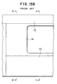
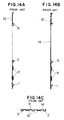
- Figs. 13-14 show a side body structure for conventional vehicles.
- various posts such as a side entrance post 2, door end post 3, and side post 4 are vertically mounted relative to a horizontally laid rocker rail 1.
- a window sill 5 Horizontally disposed between these posts are a window sill 5, a door pocket window sill 6, a frieze 7, and a door header 8.
- a door pocket post 9 and a frieze frame 10 are vertically provided relative to the aforementioned horizontally disposed members. The above mentioned members are welded together to complete the framework of a side body structure.
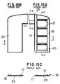
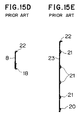
- Fig. 15 shows an example of an end body structure provided at the front and rear bridges of a railway vehicle.
- the end body structure has a pair of end entrance posts 17 and 17 on the left and right sides of the end entrance, and vertically provided corner posts 18 and 18. Between these posts are disposed a plurality of members such as a door header 19, an end rocker rail 20, and a cross beam 21.
- An arch shaped beam 22 is disposed on the posts 17 and 18 and an end outer plate 23 is welded on the upper end body structure. In this manner, the end body structure is completed.
- Japanese Patent Preliminary Publication No.61-220962 discloses a structure in which a flat side outer plate and a reinforcement having an uneven surface are put together to form a side body structure.
- the reinforcing plates has relatively small projections transversely thereof, i.e,. beads, a cross section of which being a triangle, and projections having a U-shaped cross section longitudinally of the projections.
- the reinforcing plate may have an uneven surface with rectangular projections thereon and a core material is filled between the side outer plate and the reinforcement.
- Japanese Patent Preliminary Publication No.61-220963 discloses a structure in which bead is formed on pier panels between side posts and cross members in the direction of a shear force.
- Such conventional structures have drawbacks in that the body structure requires a large number of components of and many kinds, more preparatory works when machining, and complex work operations.
- the conventional structures also require a large number of jigs for positioning the respective members relative to each other, and is complex in getting all necessary parts ready for assembly work.
- welding must be carried out at many portions, being sources of increased mechanical strains and less dimensional precision.
- the present invention was made in view of the aforementioned drawbacks and an object of the present invention is to provide a vehicle body structure according to the preamble of claim 1 which requires less number of parts, simplified part-machining and assembly operation, and insures required rigidity, lighter weight, and less dimensional distortion.
- a body structure for vehicles according to the invention is formed of a plurality of sections.
- Each of the sections has a reinforcement in an integrally continuous construction.
- the reinforcement has a plurality of through holes which reduce total weight of the reinforcement.
- the reinforcement further includes a plurality of ribs formed around the holes and is securely placed together with a surface of an outer plate.
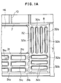
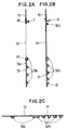
- FIGs. 1 and 2 show a body structure according to the invention.
- a vehicle body structure is constructed of a plurality of sections.
- the rocker rail 1, a side post 4, a window sill 5, and a reinforcement 11 of the prior art structure are formed of metal into a wainscot frame 31 in an integrally continuous construction as a section.
- a plurality of holes 31a are made in the section so as to reduce overall weight of the structure.
- Around the holes are formed longitudinal ribs 31b which are in place of the conventional door end posts 3 and side posts 4, and transverse ribs 31c which are in place of the conventional window sill 5 and reinforcement 11.
- the side entrance post 2, door end post 3, door pocket post 9, reinforcement 11 and 12 and door pocket window sill 6 of the prior art structure are formed of metal into a door pocket frame 32 as a section in an integrally continuous construction.
- the door pocket frame is formed with longitudinally elongated holes and transversely elongated holes therein around which longitudinally extending ribs 32b and transversely extending ribs 32c are formed, respectively.
- Above the respective sections 31 and 32 are formed a frieze 7, a door header 8, and a frieze frame 10 connected together so as to form a framework of a side body structure just as in the conventional side body structure.
- the outer plates 13, 14, and 15 may also be formed in one piece structure.
- the respective sections 31 and 32 are connected together by, for example, welding before the outer plates 13, 14, and 15 is mounted to complete a side body structure primarily used for vehicles.
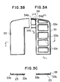
- Fig. 3 shows an vehicle body structure as a second embodiment of the invention.
- the end entrance post 17, a corner post 18, end rocker rail 20, cross beam 21, one end of arch shaped beam 22 of the prior art are formed through press into an end wall frame 33 of an integrally continuous construction.
- Two end wall frames 33 are connected together with an end entrance upper frame 34 therebetween.
- the end wall frame 33 is also formed with through holes 33a therein just as other sections are formed holes therein.
- Around the holes 33a are formed with vertically extending ribs 33b and horizontally extending ribs 33c.
- the end entrance upper frame 34 is formed with a through hole 34a and a rib 34b. Mounting an end outer plate 23 on the assembly of two end wall frames 33 and an entrance upper frame 34 completes the vehicle body structure.
- ribs of the invention are not limited to the longitudinal and transverse direction.
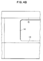
- Fig. 4 shows a third embodiment, where the wainscot frame 31 and door pocket frame 32 are provided with ribs 31d, 31e, 32d, and 32e that operate as diagonal beams. These ribs increases rigidity of the vehicle in the back and forth direction of the vehicle.
- the ribs 31d and 31e may be combined with the longitudinal and transverse ribs 31b and 31c in Fig. 1.
- the ribs may be arranged such that their longitudinal axes cross each other regardless of whether the ribs are actually crossing each other.
- FIG. 5 is a simplified rear view of a fourth embodiment seen from a passenger space 1.
- a side body structure 101 is formed of a sill plate 102, a door pocket plate 103, and a frieze plate 104.
- the side body structure 101 has a side window 105 and side entrance 106.
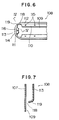
- Fig. 6 is a fragmentary rear view of the sill plate 102 expanded in part.
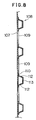
- Fig. 8 is a cross-sectional view of the sill plate 102 taken along the line III-III of Fig. 5.
- a reinforcement 108 is formed with a plurality of elongated holes 109 therein and is secured to the surface on the side of passenger space(right hand side in Fig. 8) of outer plate 107.
- the outer plate 107 and the reinforcement 108 are made of metal such as stainless steel.
- Flanges 110 and 111 are formed around the hole 109 and are secured at 115 and 116 to the passenger side surface of the outer plate 107 through, for example, spot welding.
- the reinforcement 108 has a beveled portion 112 integrally continuous with the flanges 110 and with a reinforcing portion 113 between two beveled portions.
- flanges 111 is integrally continuous with the reinforcing portion 113 via beveled portions 114.
- Fig. 7 is a cross-sectional view taken along the lines IV-IV of Fig. 6.
- Arcuate cutouts 118 continuous with the hole 109 are formed at corners of substantially rectangular hole 109 in the proximity of the beveled portions 112 and 114 and flanges 110 and 111, so that inwardly curved beveled portions 109 are formed when a flat sheet of metal 108 in Fig. 9 is press-worked.
- Fig. 9 shows the flat shaped reinforcement 108 before it is subjected to plastic deformation into that shown in Fig. 8.
- a hole 109 and a cutout 118 are formed near the flanges 110 and 111.
- the flanges 110 and 111 and bevelled portions 112 and 114 are bent by pressing while the bevelled portion 119 near the cutout 118 is formed by drawing.
- the cutout 118 is provided so as to prevent wrinkles or cracks due to tensile force acting thereon when the reinforcement is drawn. If the reinforcement has good malleability, then the cutout 118 is not required.
- Fig. 10 is a horizontal cross-sectional view of the sill plate 102 and the vicinity thereof.
- the sill plate 102 is spot-welded at the flange 110 of reinforcement 108 to a post 120. Then an interior plate 121 is, for example, bolted to the post 120 to define the passenger space.
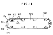
- Fig. 11 is an expanded front view of a fifth embodiment.
- a flange 110a is formed only at a portion where the reinforcement 108 is spot-welded to the outer plate 107.
- the fifth embodiment is advantageous in reducing total weight and saving the costs of material.
- the outer plate 107 may be made not only of metal such as a sheet of stainless steel but also of other materials such as synthetic resin and FRP(fiber reinforced plastics).
- the outer plate and the flanges of reinforcement may be connected together by, for example, spot welding, riveting, adhesives, and a fastener such as bolt and nut.
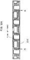
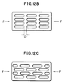
- Fig. 12 shows a sixth embodiment of the invention.
- Fig. 12A shows directions of forces exerted to the wainscot 202 when the vehicle body is supported on the bogies at arrows M
- Fig. 12B is a view, expanded in part, of the wainscot having elongated holes aligned in parallel with each other
- Fig. 12C is a view, expanded in part, of the wainscot having elongated holes aligned in zigzag arrangement.
- the wainscot 202 may buckle at "D" when compressive forces are applied in the direction of arrows F.
- the buckling of the wainscot 202 as well as the outer plate placed together with the wainscot may be prevented by arranging the elongated holes in zigzag fashion with the holes elongated in the direction of applied forces. In this manner, the mechanical strength of side body structure is enhanced.
- Each section of a side body structure may be formed in an integrally continuous construction by the use of press, which has a relatively high degree of freedom in making a variety of shapes of a structure.
- the integrally continuous construction of the respective sections reduces the number of parts and time required for assembling the sections, improving productivity.
- Ribs may be formed in a variety of shapes and diagonal beams may be formed, if necessary, for more rigidity of the section.
- the lighter weight of the side body structure is implemented by pressing a light, thin plate through which holes are punched through. Further, preprocessed portions of the respective sections may easily be formed in proper shapes before the sections are finally connected together.
- the frame of side body structure is constructed of large size sections which allows least strain, least dimensional error, and ease of manufacture of side body structure.
- the thus completed vehicle body will have lighter weights, sufficient rigidity against loads exerted, and good appearance.
- Providing ribs improves the modulus of section and the second moment of area, so that rigidity against out-plane bending and in-plane bending is increased.
- the sill plate 102 withstands large axial forces in the longitudinal direction (leftwards and rightwards in Figs. 5 and 6) of the hole 109, improving the buckling strength of a body structure.
- the reinforcement provided around the holes improves the rigidity of the respective sections against compression forces exerted at right angles with respect to the longitudinal length of the holes 109. Meanwhile, the portions without reinforcement are rather flexible preventing plastic deformation which may be caused by compressive forces.
- the corner portions of the hole 109 has bevelled portions 119 which have been rather rounded through drawing into a so-called three dimensional shape which withstands particularly a large torsional force exerted to the entire section, so that crippling will not result.
- a cutout 118 formed near the beveled portion 119 enables the flat sheet of metal as shown in Fig. 9 to be pressed with a relatively small force. Thus, there is no need for good malleability of the material.
- a plurality of elongated holes are arranged in rows extending in a direction of exerted forces such that each elongated hole is positioned between adjacent two elongated holes in adjacent row. This zigzag arrangement is particularly advantageous in increasing mechanical strength of wainscot against bucking forces.
Landscapes
- Engineering & Computer Science (AREA)
- Life Sciences & Earth Sciences (AREA)
- Wood Science & Technology (AREA)
- Mechanical Engineering (AREA)
- Body Structure For Vehicles (AREA)
Claims (11)
- Structure de caisse de véhicule comprenant une pluralité de parties reliées les unes aux autres pour constituer la dite structure de caisse, chacune des parties comprenant :
un renforcement (31, 32, 33, 34, 108) sous forme d'une construction intégralement continue ;
une pluralité de trous (31a, 32a, 33a, 109) formés dans la dite partie de manière à réduire son poids ;
une pluralité de nervures (31b- 31e, 32b - 32e, 33b, 33c, 113) formées autour des dits trous (31a, 32a) ;et
une plaque extérieure (13, 14, 15, 107) fixée à une surface de la dite partie ;
dans laquelle les dites nervures (31b - 31e , 32b - 32e, 33b, 33c, 113) formées autour des dits trous (31a, 32a, 109) comportent des collerettes (110, 110a, 111) s'étendant dans les dits trous (31a, 32a, 109) ;
caractérisée en ce que la dite plaque extérieure est fixée du côté extérieur des dites collerettes; - Structure de caisse de véhicule suivant la revendication 1, dans laquelle les dits trous sont rectangulaires et les dites nervures (31d, 31e, 32d, 32e) sont formées de manière à s'étendre dans les dits trous pour se croiser diagonalement.
- Structure de caisse de véhicule suivant la revendication 1, dans laquelle les dites nervures (31a - 31c , 32a - 32c) comprennent des nervures disposées en rangées et des nervures disposées en file .
- Structure de caisse de véhicule suivant une revendication précédente, dans laquelle la dite pluralité de parties de caisse sont en métal.
- Structure de caisse de véhicule suivant la revendication 4, dans laquelle les dites nervures (113) sont formées par déformation d'une portion périphérique du dit trou (109), par étirage.
- Structure de caisse de véhicule suivant la revendication 5, dans laquelle le dit trou (109) est sensiblement rectangulaire et comporte des découpes (118) à ses quatre angles, la dite portion périphérique incluant les dites découpes étant déformée par étirage de manière à engendrer les dites nervures (113).
- Structure de caisse de véhicule suivant la revendication 1, dans laquelle les dites nervures (113) consistent en une portion de renforcement intégralement en continuité avec les dites collerettes (110) et située à l'opposé de la dite plaque extérieure (107) lorsque la dite partie est connectée à la dite plaque extérieure (107).
- Structure de caisse de véhicule suivant la revendication 1, dans laquelle les dits trous (109) sont des trous allongés en rangées s'étendant dans une direction de charges appliquées (M), les dits trous (109) étant agencés en zigzag de sorte que chaque trou se trouve entre deux trous adjacents d'une rangée adjacente.
- Structure de caisse de véhicule suivant la revendication 1, dans laquelle la dite pluralité de parties sont soudées par points aux dites plaques extérieures (107).
- Structure de caisse de véhicule suivant la revendication 1, dans laquelle la dite pluralité de parties sont fabriquées en résine synthétique.
- Structure de caisse de véhicule suivant la revendication 1, dans laquelle la dite pluralité de parties sont fabriquées en matière plastique renforcée par des fibres.
Applications Claiming Priority (4)
| Application Number | Priority Date | Filing Date | Title |
|---|---|---|---|
| JP2246085A JP2978225B2 (ja) | 1990-09-18 | 1990-09-18 | 車両の側構体構造 |
| JP246085/90 | 1990-09-18 | ||
| JP1990099099U JP2592092Y2 (ja) | 1990-09-20 | 1990-09-20 | 鉄道車両の構体用板材 |
| JP99099/90U | 1990-09-20 |
Publications (3)
| Publication Number | Publication Date |
|---|---|
| EP0477727A2 EP0477727A2 (fr) | 1992-04-01 |
| EP0477727A3 EP0477727A3 (en) | 1992-05-06 |
| EP0477727B1 true EP0477727B1 (fr) | 1996-05-08 |
Family
ID=26440253
Family Applications (1)
| Application Number | Title | Priority Date | Filing Date |
|---|---|---|---|
| EP91115739A Expired - Lifetime EP0477727B1 (fr) | 1990-09-18 | 1991-09-17 | Structure de caisse de véhicule |
Country Status (4)
| Country | Link |
|---|---|
| US (1) | US5285730A (fr) |
| EP (1) | EP0477727B1 (fr) |
| KR (1) | KR960000810B1 (fr) |
| DE (1) | DE69119339T2 (fr) |
Families Citing this family (4)
| Publication number | Priority date | Publication date | Assignee | Title |
|---|---|---|---|---|
| DE19612342C2 (de) * | 1996-03-28 | 2001-09-20 | Talbot Gmbh & Co Kg | Aufbau für Fahrzeuge |
| US6196136B1 (en) * | 1996-06-19 | 2001-03-06 | Hitachi, Ltd. | Car and side structure for car and method of manufacturing the same |
| JP3675714B2 (ja) * | 2000-12-20 | 2005-07-27 | 株式会社日立製作所 | 鉄道車両の妻の製作方法及び鉄道車両の車体 |
| FR2901764B1 (fr) * | 2006-06-02 | 2019-08-09 | Alstom Transport Technologies | Face laterale de caisse de vehicule ferroviaire. |
Family Cites Families (13)
| Publication number | Priority date | Publication date | Assignee | Title |
|---|---|---|---|---|
| US1224050A (en) * | 1914-12-07 | 1917-04-24 | William P Worth | Railway-car. |
| US1172095A (en) * | 1915-01-09 | 1916-02-15 | William P Worth | Railway-car. |
| US1273564A (en) * | 1915-12-31 | 1918-07-23 | William P Worth | Car construction. |
| US1485329A (en) * | 1923-02-05 | 1924-02-26 | Entpr Railway Equipment Co | Railway-car construction |
| FR596791A (fr) * | 1924-07-25 | 1925-10-31 | Travaux Dyle Et Bacalan Sa | Perfectionnements à la construction des voitures de chemins de fer |
| US2164646A (en) * | 1937-10-27 | 1939-07-04 | Edahl Knute | Metallic wall structure |
| BE480233A (fr) * | 1941-05-09 | |||
| US3585942A (en) * | 1969-02-11 | 1971-06-22 | Pullman Inc | Railroad boxcar side construction |
| US4076166A (en) * | 1975-10-02 | 1978-02-28 | Fmc Corporation | Roof for railway car and method of making same |
| DE2707573A1 (de) * | 1977-02-22 | 1978-08-24 | Krupp Gmbh | Fachwerktraeger mit verbessertem kraftfluss |
| JPS5675272A (en) * | 1979-11-26 | 1981-06-22 | Mazda Motor Corp | Adhesion structure of reinforcement to automobile |
| DE3222887C2 (de) * | 1982-06-18 | 1985-06-20 | Daimler-Benz Ag, 7000 Stuttgart | Element hoher Steifigkeit, insbesondere Wand- oder Dachelement für selbsttragende Omnibusaufbauten |
| JPS61220962A (ja) * | 1985-03-27 | 1986-10-01 | 株式会社日立製作所 | 客電車の側構体 |
-
1991
- 1991-09-17 DE DE69119339T patent/DE69119339T2/de not_active Expired - Fee Related
- 1991-09-17 EP EP91115739A patent/EP0477727B1/fr not_active Expired - Lifetime
- 1991-09-17 US US07/761,186 patent/US5285730A/en not_active Expired - Lifetime
- 1991-09-18 KR KR1019910016250A patent/KR960000810B1/ko not_active Expired - Lifetime
Also Published As
| Publication number | Publication date |
|---|---|
| KR960000810B1 (ko) | 1996-01-13 |
| US5285730A (en) | 1994-02-15 |
| EP0477727A3 (en) | 1992-05-06 |
| EP0477727A2 (fr) | 1992-04-01 |
| DE69119339T2 (de) | 1996-09-05 |
| DE69119339D1 (de) | 1996-06-13 |
Similar Documents
| Publication | Publication Date | Title |
|---|---|---|
| US4462629A (en) | Construction of car structure | |
| KR101157000B1 (ko) | 차체 구조 부재용 성형품 | |
| CA1297927C (fr) | Poutrelle-renfort de securite pour portieres laterales de vehicule automobile | |
| EP4253114B1 (fr) | Boîtier de batterie automobile et son procédé de fabrication | |
| US20190381960A1 (en) | Bumper system | |
| US6196136B1 (en) | Car and side structure for car and method of manufacturing the same | |
| EP0561369B1 (fr) | Construction d'une caisse de voiture | |
| JP2533663B2 (ja) | 鉄道車両構体 | |
| US11884332B2 (en) | Automobile hood | |
| GB2196584A (en) | Load bearing structures for vehicles | |
| US20040145215A1 (en) | Structural element and body structure including the same | |
| JP2875106B2 (ja) | 構造部材の補強構造及び補強金具 | |
| EP0477727B1 (fr) | Structure de caisse de véhicule | |
| US6305738B1 (en) | Door frame for a motor vehicle | |
| EP0347132A2 (fr) | Caisse de véhicule ferroviaire | |
| JPS639480Y2 (fr) | ||
| JPS61169376A (ja) | ピラ−とサイドシルとの結合部構造 | |
| JP2821163B2 (ja) | 鉄道車両の屋根構体 | |
| JP7416657B2 (ja) | 複合構造体 | |
| JPH08282532A (ja) | 車両のフレーム | |
| JPH0924864A (ja) | クロスメンバ構造 | |
| JP2866857B2 (ja) | 鉄道車両用台車の側ばり構造 | |
| JPH10184075A (ja) | 鋼製耐震壁 | |
| JP2592092Y2 (ja) | 鉄道車両の構体用板材 | |
| JP3371710B2 (ja) | 中空構造材 |
Legal Events
| Date | Code | Title | Description |
|---|---|---|---|
| PUAI | Public reference made under article 153(3) epc to a published international application that has entered the european phase |
Free format text: ORIGINAL CODE: 0009012 |
|
| PUAL | Search report despatched |
Free format text: ORIGINAL CODE: 0009013 |
|
| AK | Designated contracting states |
Kind code of ref document: A2 Designated state(s): DE FR GB |
|
| AK | Designated contracting states |
Kind code of ref document: A3 Designated state(s): DE FR GB |
|
| 17P | Request for examination filed |
Effective date: 19920904 |
|
| 17Q | First examination report despatched |
Effective date: 19931216 |
|
| GRAH | Despatch of communication of intention to grant a patent |
Free format text: ORIGINAL CODE: EPIDOS IGRA |
|
| GRAA | (expected) grant |
Free format text: ORIGINAL CODE: 0009210 |
|
| AK | Designated contracting states |
Kind code of ref document: B1 Designated state(s): DE FR GB |
|
| REF | Corresponds to: |
Ref document number: 69119339 Country of ref document: DE Date of ref document: 19960613 |
|
| ET | Fr: translation filed | ||
| PLBE | No opposition filed within time limit |
Free format text: ORIGINAL CODE: 0009261 |
|
| STAA | Information on the status of an ep patent application or granted ep patent |
Free format text: STATUS: NO OPPOSITION FILED WITHIN TIME LIMIT |
|
| 26N | No opposition filed | ||
| PGFP | Annual fee paid to national office [announced via postgrant information from national office to epo] |
Ref country code: FR Payment date: 19990909 Year of fee payment: 9 |
|
| PGFP | Annual fee paid to national office [announced via postgrant information from national office to epo] |
Ref country code: GB Payment date: 19990915 Year of fee payment: 9 |
|
| PGFP | Annual fee paid to national office [announced via postgrant information from national office to epo] |
Ref country code: DE Payment date: 19991123 Year of fee payment: 9 |
|
| PG25 | Lapsed in a contracting state [announced via postgrant information from national office to epo] |
Ref country code: GB Free format text: LAPSE BECAUSE OF NON-PAYMENT OF DUE FEES Effective date: 20000917 |
|
| GBPC | Gb: european patent ceased through non-payment of renewal fee |
Effective date: 20000917 |
|
| PG25 | Lapsed in a contracting state [announced via postgrant information from national office to epo] |
Ref country code: FR Free format text: LAPSE BECAUSE OF NON-PAYMENT OF DUE FEES Effective date: 20010531 |
|
| PG25 | Lapsed in a contracting state [announced via postgrant information from national office to epo] |
Ref country code: DE Free format text: LAPSE BECAUSE OF NON-PAYMENT OF DUE FEES Effective date: 20010601 |
|
| REG | Reference to a national code |
Ref country code: FR Ref legal event code: ST |