EP0477769A2 - Dispositif de collage transversal pour l'application de colle sur une bande en mouvement - Google Patents
Dispositif de collage transversal pour l'application de colle sur une bande en mouvement Download PDFInfo
- Publication number
- EP0477769A2 EP0477769A2 EP91115901A EP91115901A EP0477769A2 EP 0477769 A2 EP0477769 A2 EP 0477769A2 EP 91115901 A EP91115901 A EP 91115901A EP 91115901 A EP91115901 A EP 91115901A EP 0477769 A2 EP0477769 A2 EP 0477769A2
- Authority
- EP
- European Patent Office
- Prior art keywords
- glue
- cross
- glue cylinder
- application
- guide
- Prior art date
- Legal status (The legal status is an assumption and is not a legal conclusion. Google has not performed a legal analysis and makes no representation as to the accuracy of the status listed.)
- Granted
Links
Images


Classifications
-
- B—PERFORMING OPERATIONS; TRANSPORTING
- B05—SPRAYING OR ATOMISING IN GENERAL; APPLYING FLUENT MATERIALS TO SURFACES, IN GENERAL
- B05C—APPARATUS FOR APPLYING FLUENT MATERIALS TO SURFACES, IN GENERAL
- B05C1/00—Apparatus in which liquid or other fluent material is applied to the surface of the work by contact with a member carrying the liquid or other fluent material, e.g. a porous member loaded with a liquid to be applied as a coating
- B05C1/04—Apparatus in which liquid or other fluent material is applied to the surface of the work by contact with a member carrying the liquid or other fluent material, e.g. a porous member loaded with a liquid to be applied as a coating for applying liquid or other fluent material to work of indefinite length
- B05C1/08—Apparatus in which liquid or other fluent material is applied to the surface of the work by contact with a member carrying the liquid or other fluent material, e.g. a porous member loaded with a liquid to be applied as a coating for applying liquid or other fluent material to work of indefinite length using a roller or other rotating member which contacts the work along a generating line
- B05C1/10—Apparatus in which liquid or other fluent material is applied to the surface of the work by contact with a member carrying the liquid or other fluent material, e.g. a porous member loaded with a liquid to be applied as a coating for applying liquid or other fluent material to work of indefinite length using a roller or other rotating member which contacts the work along a generating line the liquid or other fluent material being supplied from inside the roller
-
- B—PERFORMING OPERATIONS; TRANSPORTING
- B65—CONVEYING; PACKING; STORING; HANDLING THIN OR FILAMENTARY MATERIAL
- B65H—HANDLING THIN OR FILAMENTARY MATERIAL, e.g. SHEETS, WEBS, CABLES
- B65H45/00—Folding thin material
- B65H45/12—Folding articles or webs with application of pressure to define or form crease lines
- B65H45/30—Folding in combination with creasing, smoothing or application of adhesive
-
- Y—GENERAL TAGGING OF NEW TECHNOLOGICAL DEVELOPMENTS; GENERAL TAGGING OF CROSS-SECTIONAL TECHNOLOGIES SPANNING OVER SEVERAL SECTIONS OF THE IPC; TECHNICAL SUBJECTS COVERED BY FORMER USPC CROSS-REFERENCE ART COLLECTIONS [XRACs] AND DIGESTS
- Y10—TECHNICAL SUBJECTS COVERED BY FORMER USPC
- Y10S—TECHNICAL SUBJECTS COVERED BY FORMER USPC CROSS-REFERENCE ART COLLECTIONS [XRACs] AND DIGESTS
- Y10S118/00—Coating apparatus
- Y10S118/15—Roller structure
Definitions
- Cross glue device for applying glue to a moving material web
- the invention relates to a cross-glue device according to the preamble of claim 1.
- Cross glue devices are e.g. B. become known from EP 02 09 110 B1.
- This device has the disadvantage that the diameter can only be changed by exchanging inserts.
- the glue cylinder has a constant diameter that is matched to the plate cylinder with the printing plate placed on it.
- the invention has for its object to provide a glue cylinder with which it is possible to influence the paper web tension between the printing device and the folding device without having to replace the glue cylinder or parts thereof.
- the advantages that can be achieved with the invention are, in particular, that when using different paper types / thicknesses and using different paper web tensions between the printing unit and folding device, depending on the paper type / thickness or paper web tension, a cross-glue cylinder with a fixed diameter adapted to those conditions is not used got to. It is therefore possible to set the paper web tension exactly for different paper types and thicknesses. Debris and glue traps between cross glue bars and their adjacent guide surfaces are avoided because the cross glue bar can be adapted exactly to the curvature of the guide surfaces and does not need to protrude beyond them.
- the fluttering of the paper web having a periodic glue application can be avoided and wrinkles in the paper web can thus be avoided.
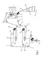
- the first strand 2 runs over a subsequent torque or / and speed-adjustable first strand pulling roller 8, a known longitudinal register device 14, several paper guide rollers 4, a torque-controlled and / or speed-controlled folder feed roller 9, and a former 11 into the folder 6 a.
- the second strand 3 of the paper web 1 runs over known turning bars 12 in such a way that strand 3 comes to lie exactly over the strand 2. Then it runs over a second continuous drawing roller 13, which can be torque and / or speed-controlled or controlled, a second longitudinal register device 14, a plurality of paper guide rollers 4, a cross-gluing device 16, on the first strand 2 onto the folder inlet Pull roller 9.
- both strands 2, 3 are glued to one another by a narrow glue application located on the strand 3 and lying transversely to the running direction of the two strands 2 and 3.
- the cross-glue device 16 consists of a cross-glue cylinder 17 and a pressure bar 19 arranged on a shaft 18.
- the cross-glue cylinder 17 and shaft 18 rotate at a peripheral speed which is adapted to the strand speed.
- a distance between the axes of rotation of the cross-glue cylinder 17 and the shaft 18 can be changed, the position of the axis of rotation of the cross-glue cylinder 17 preferably being fixed.
- the driven cross glue cylinder 17 has in the embodiment 2, 180 ° opposite known glue application bar 21, 22 each with a z. B. continuous glue outlet longitudinal slot.
- the transverse glue cylinder 17 has a circular cross section for the smallest possible extent.
- the surface of the glue application bars 21, 22 and the convex pipe segments 23, 24, 26, 27 connected to them in a form-fitting manner are also adapted to this.
- the tube segments 23, 24, 26, 27 have the shape of part of a circular ring with a central angle ⁇ 90 °.
- Glue application bar 21 covers a circumferential angle of 180 ° together with the pipe segments 23, 24 which are positively connected to it.
- Glue application bar 22 covers a circumferential angle of 180 ° together with the pipe segments 26, 27 which are positively connected to it.
- glue application bars 21 together with the tube segments 23, 24 and glue application bars 22 together with the tube segments 26, 27 are arranged so as to be radially displaceable and lockable.
- a guide cuboid 10 or 20 is arranged with a shaft 28 in the vicinity of its two ends and each is integrally connected to it (for example welded).
- a support disk 31 or 32 is fastened in a rotationally fixed manner to the shaft 28. They are parallel to each other.
- Each of the support disks 31, 32 has a bearing bore 33, 34, 35, 36 in the vicinity of its end faces.
- An eccentric shaft 44 is mounted in the bearing bores 33, 34, and an eccentric shaft 46 is rotatably mounted in the bearing bores 35, 36.
- the eccentric shaft 44 has an external square 47 at one of its ends.
- the eccentric shaft 46 has an outer square 48 at one of its ends. The square edges 47 and 48 serve to turn the eccentric shafts 44, 46 by means of an open-ended spanner.
- the eccentric shaft 44 ends in its first end in two outer eccentrics 37 and inner eccentrics 38 arranged directly next to one another and in its second end in two outer eccentrics 39 and inner eccentrics 40 arranged directly next to one another.
- the eccentric shaft 46 ends in its first end in two outer eccentrics 41 and inner eccentrics 42 arranged directly next to one another and in its second end also in an outer and inner eccentric (not shown), which have the same dimensions as the eccentrics 39, 40.
- the eccentricity of the outer 37, 39; 41 and not shown outer eccentric of the eccentric shaft 46 and the respective opposite inner eccentrics 38, 40; 42 and not shown eccentric of the eccentric shaft 44 is selected so that the cuboid sliding blocks 43 - 52; 49-51; 45-53; and move the two sliding blocks 50-15, not shown, on the two eccentrics on the second end of the eccentric shaft 46 in the opposite direction. This ensures that the glue application bars 21 and 22 move together with the tube segments 23-24 and 26-27 simultaneously in the opposite direction.
- each sliding block 43, 45, 49, 52, 53, 51 etc. is provided with a hole matched to the respective eccentric.
- an outer adjusting disk 54 and 55 and an inner adjusting disk 56 and 57 are welded close to both ends of the cross-glue cylinder body 30 .
- All adjustment discs 54 to 57 are designed the same.
- Each adjusting disk 54 to 57 has an open recess 58 and 59 along its center line.
- the dimensions of these recesses 58, 59 are adapted to the shaft-fixed guide blocks 10 and 20, respectively, in such a way that the adjusting disks 54 to 57 can be moved on them.
- An upper prong 60, 61 and a lower prong 62, 63 of the adjusting disks 54 and 56 extend to the left and right of the recesses 58 of the left part of the transverse glue cylinder body 30.
- An upper tine 64, 65 and a lower tine 66, 67 of the adjusting disks 55 and 57 extend to the left and right of the recesses 59 of the right part of the transverse glue cylinder body 30.
- the outer upper 60, 64 and inner upper tines 61, 65 have an upwardly open rectangular guide cutout 71, 72 and 73.74, respectively.
- the outer lower 62, 66 and inner lower prongs 63, 67 have a downwardly open rectangular guide cutout 68, 69 and 70, 75, respectively. All guide cutouts have the same dimensions, as do all sliding blocks.
- the adjusting disks 54 to 57 each have two bores 76, 77 and 78, 79.
- the holes 76 and 77 of the left adjusting disks 54 and 56 lie over the holes 78 and 79 of the right adjusting disks 55 and 57 and the threaded bores 80, 81 and 82, 83 of the supporting disks 31 and 32.
- Screw 84 passes through the bores 76, 78 and is in engagement with the threaded bore 82.
- Screw 85 passes through the bores 77, 79 and is in engagement with the threaded bore 81.
- Screw 86 passes through the bores 76, 78 and is in engagement with the threaded bore 80.
- Screw 87 passes through the bores 77, 79 and is in engagement with the threaded bore 83.
- the screws 84 to 87 serve to fix a set position of the glue application bars 21, 22.
- Each end face 88 to 91 of the tube segments 23, 24, 26, 27 is provided with a semicircular groove 92 to 95.
- the semicircular grooves 88 and 91 enclose a rubber cord 96
- the semicircular grooves 89 and 90 enclose a rubber cord 97.
- the rubber cords 96 and 97 are dimensioned so that they are at max. adjusted circumference of the cross-glue cylinder body 30, keep the gap between the end faces 88 to 91 or 89 to 90 securely closed in order to disappear as completely as possible in the semicircular grooves 92-95 and 93-94 with the smallest circumference.
Landscapes
- Coating Apparatus (AREA)
Applications Claiming Priority (4)
| Application Number | Priority Date | Filing Date | Title |
|---|---|---|---|
| DE4030271 | 1990-09-25 | ||
| DE4030271 | 1990-09-25 | ||
| DE4129404 | 1991-09-04 | ||
| DE4129404A DE4129404C2 (de) | 1990-09-25 | 1991-09-04 | Querleim-Vorrichtung zum Aufbringen von Leim auf eine bewegte Materialbahn |
Publications (3)
| Publication Number | Publication Date |
|---|---|
| EP0477769A2 true EP0477769A2 (fr) | 1992-04-01 |
| EP0477769A3 EP0477769A3 (en) | 1992-08-05 |
| EP0477769B1 EP0477769B1 (fr) | 1995-07-26 |
Family
ID=25897169
Family Applications (1)
| Application Number | Title | Priority Date | Filing Date |
|---|---|---|---|
| EP91115901A Expired - Lifetime EP0477769B1 (fr) | 1990-09-25 | 1991-09-19 | Dispositif de collage transversal pour l'application de colle sur une bande en mouvement |
Country Status (4)
| Country | Link |
|---|---|
| US (1) | US5312488A (fr) |
| EP (1) | EP0477769B1 (fr) |
| JP (1) | JPH0651147B2 (fr) |
| DE (2) | DE4129404C2 (fr) |
Cited By (2)
| Publication number | Priority date | Publication date | Assignee | Title |
|---|---|---|---|---|
| WO2000056652A1 (fr) * | 1999-03-19 | 2000-09-28 | Koenig & Bauer Aktiengesellschaft | Procede et dispositif d'introduction pour au moins une bande de papier |
| US7387601B2 (en) | 2004-03-26 | 2008-06-17 | Koenig & Bauer Aktiengesellschaft | Devices and methods for drawing at least one web of material or at least one web strand into a folding apparatus |
Families Citing this family (6)
| Publication number | Priority date | Publication date | Assignee | Title |
|---|---|---|---|---|
| DE4236320C2 (de) * | 1992-10-28 | 1998-07-16 | Hella Kg Hueck & Co | Gehäuse für ein elektrisches Gerät |
| DE29502723U1 (de) * | 1995-02-18 | 1996-06-20 | Planatol Klebetechnik GmbH, 83101 Rohrdorf | Behandlungsvorrichtung, insbesondere Querleimwerk |
| US5915305A (en) * | 1998-04-27 | 1999-06-29 | Ward; Donald A. | Method and apparatus for handling sheet material |
| US6740733B2 (en) * | 2001-11-30 | 2004-05-25 | Shell Oil Company | Process and apparatus for crystallization of polytrimethylene terephthalate (PTT) |
| US7021210B2 (en) * | 2004-03-22 | 2006-04-04 | Printing Research, Inc. | Printing press cylinder |
| DE102005045038B3 (de) * | 2005-09-21 | 2007-04-12 | Koenig & Bauer Ag | Transportvorrichtung zum Einzug einer Materialbahn |
Family Cites Families (15)
| Publication number | Priority date | Publication date | Assignee | Title |
|---|---|---|---|---|
| US1098060A (en) * | 1907-12-23 | 1914-05-26 | Brown Binnian Company | Printing and cutting machine. |
| US1047206A (en) * | 1912-04-01 | 1912-12-17 | Albert M E Grignard | Means for supporting cylinders. |
| US1672842A (en) * | 1924-02-18 | 1928-06-05 | Charles Wagner Litho Machinery | Coating machine |
| US2583889A (en) * | 1948-02-17 | 1952-01-29 | Schoonenberg Pancras Johannes | Expansible printing cylinder for rotary multicolor printing |
| FR1085252A (fr) * | 1953-10-19 | 1955-01-31 | Porte-cliché d'impression pour machines à imprimer | |
| US3340804A (en) * | 1966-01-24 | 1967-09-12 | Control Print Corp | Marking head assembly for code marking machines |
| US3585097A (en) * | 1968-05-22 | 1971-06-15 | Phillips Petroleum Co | Expandable drum and heat sealing means |
| DE2457500A1 (de) * | 1974-12-05 | 1976-06-10 | Reich Maschf Gmbh Karl | Anleimgeraet fuer ein schmelzkleberbeschichtetes umleimerband |
| DE2500174A1 (de) * | 1975-01-03 | 1976-07-08 | Windmoeller & Hoelscher | Leimauftragswerk |
| US4343011A (en) * | 1980-03-17 | 1982-08-03 | Thomas M. Murray | Facsimile apparatus |
| DE3207620C2 (de) * | 1982-03-03 | 1985-07-25 | Albert-Frankenthal Ag, 6710 Frankenthal | Vorrichtung zum Aufbringen eines Leimstreifens auf eine bewegte Materialbahn |
| DE3222335C2 (de) * | 1982-06-14 | 1985-01-03 | Planatolwerk W. Hesselmann, Chemische und Maschinenfabrik für Klebetechnik, GmbH & Co KG, 8201 Rohrdorf | Vorrichtung zum Auftragen eines Klebstoffes in Form einer Queranleimung auf eine Bahn |
| JPS606464A (ja) * | 1983-06-24 | 1985-01-14 | Kobe Dock Kogyo Kk | 版胴 |
| DE3525805A1 (de) * | 1985-07-19 | 1987-01-29 | Hesselmann Planatolwerk H | Vorrichtung zum auftragen eines klebstoffes in form einer queranleimung |
| DE3540581A1 (de) * | 1985-11-15 | 1987-05-21 | Roland Man Druckmasch | Druckwerkzylinder mit einem in dessen zylindergrube angeordneten fuellstueck |
-
1991
- 1991-09-04 DE DE4129404A patent/DE4129404C2/de not_active Expired - Fee Related
- 1991-09-19 DE DE59106078T patent/DE59106078D1/de not_active Expired - Fee Related
- 1991-09-19 EP EP91115901A patent/EP0477769B1/fr not_active Expired - Lifetime
- 1991-09-24 US US07/764,721 patent/US5312488A/en not_active Expired - Fee Related
- 1991-09-25 JP JP3245431A patent/JPH0651147B2/ja not_active Expired - Lifetime
Cited By (6)
| Publication number | Priority date | Publication date | Assignee | Title |
|---|---|---|---|---|
| WO2000056652A1 (fr) * | 1999-03-19 | 2000-09-28 | Koenig & Bauer Aktiengesellschaft | Procede et dispositif d'introduction pour au moins une bande de papier |
| US6705499B1 (en) | 1999-03-19 | 2004-03-16 | Koenig & Bauer Aktiengesellschaft | Rollers for guiding paper webs |
| US6821240B1 (en) | 1999-03-19 | 2004-11-23 | Koenig & Bauer Aktiengesellschaft | Longitudinal folding device |
| US6929710B1 (en) | 1999-03-19 | 2005-08-16 | Koenig & Bauer Aktiengesellschaft | Method and device for winding up at least one paper web |
| US7066368B1 (en) | 1999-03-19 | 2006-06-27 | Koenig & Bauer Aktiengesellschaft | Paper web draw-in device for a web-fed printing press |
| US7387601B2 (en) | 2004-03-26 | 2008-06-17 | Koenig & Bauer Aktiengesellschaft | Devices and methods for drawing at least one web of material or at least one web strand into a folding apparatus |
Also Published As
| Publication number | Publication date |
|---|---|
| JPH0651147B2 (ja) | 1994-07-06 |
| JPH04247258A (ja) | 1992-09-03 |
| DE4129404A1 (de) | 1992-03-26 |
| US5312488A (en) | 1994-05-17 |
| EP0477769B1 (fr) | 1995-07-26 |
| EP0477769A3 (en) | 1992-08-05 |
| DE59106078D1 (de) | 1995-08-31 |
| DE4129404C2 (de) | 1993-12-09 |
Similar Documents
| Publication | Publication Date | Title |
|---|---|---|
| DE2924800C2 (de) | Drosselvorrichtung für eine zweiwellige Schneckenmaschine | |
| DE4129404C2 (de) | Querleim-Vorrichtung zum Aufbringen von Leim auf eine bewegte Materialbahn | |
| DE3103261C2 (fr) | ||
| DE202004021649U1 (de) | Vorrichtung zur Erzeugung von Markierungslinien | |
| EP0547386A1 (fr) | Appareil à épiler | |
| DE3042427C2 (de) | Doppelschneckenstrangpresse zum Verarbeiten von thermoplastischen Formmassen, insbesondere Kunststoffen | |
| DE69313005T2 (de) | Vorrichtung zur Herstellung von wenigstens einem fortlaufenden Strang aus Rauchmaterial | |
| DE2613088C2 (de) | Vorrichtung zum kontinuierlichen Einstellen des Abstandes zwischen den feststehenden und beweglichen Stäben des Sortierzylinders einer Sortiermaschine für Gemüse od.dgl. Produkte | |
| DE3134824A1 (de) | Vorrichtung zur achsenlosen lagerung sowie zum auf- und ablaengen und gleichzeitigen messen von spulenkoerpern | |
| DE3831182C2 (fr) | ||
| DE4125706C1 (fr) | ||
| DE2738537C3 (de) | Drahteinzugapparat, insbesondere fur eine Umformpresse | |
| EP0679505A1 (fr) | Outil de travail, spécialement outil d'emboutissage transversal pour matériau en couches | |
| DE3441100C2 (fr) | ||
| DE4026238C1 (fr) | ||
| DE2905631C2 (de) | Walzgerüst mit mindestens einer von einer losen drehbaren Hülse umgebenden Stützwalze | |
| EP0714770B1 (fr) | Dispositif pour transporter du papier | |
| EP0209110B1 (fr) | Dispositif pour l'application d'un adhésif en forme de collage transversal | |
| EP0705690A1 (fr) | Rouleau de guidage de feuilles avec un diamètre extérieur réglable | |
| DE2755210B2 (de) | Heftklammerschließvorrichtung | |
| EP2463040B1 (fr) | Machine de dressage de fil rotative | |
| DE10306884B3 (de) | Auftragskopf mit Drehschieberverschluss | |
| EP0749928A1 (fr) | Cylindre de pliage | |
| DE9014379U1 (de) | Querleim-Vorrichtung zum Aufbringen von Leim auf eine bewegte Materialbahn | |
| DE102004020301B3 (de) | Umlenkwalze in einem Überbau eines Falzapparates einer Rotationsdruckmaschine |
Legal Events
| Date | Code | Title | Description |
|---|---|---|---|
| PUAI | Public reference made under article 153(3) epc to a published international application that has entered the european phase |
Free format text: ORIGINAL CODE: 0009012 |
|
| AK | Designated contracting states |
Kind code of ref document: A2 Designated state(s): CH DE FR GB IT LI SE |
|
| PUAL | Search report despatched |
Free format text: ORIGINAL CODE: 0009013 |
|
| AK | Designated contracting states |
Kind code of ref document: A3 Designated state(s): CH DE FR GB IT LI SE |
|
| 17P | Request for examination filed |
Effective date: 19921029 |
|
| 17Q | First examination report despatched |
Effective date: 19940223 |
|
| ITF | It: translation for a ep patent filed | ||
| GRAA | (expected) grant |
Free format text: ORIGINAL CODE: 0009210 |
|
| AK | Designated contracting states |
Kind code of ref document: B1 Designated state(s): CH DE FR GB IT LI SE |
|
| ET | Fr: translation filed | ||
| GBT | Gb: translation of ep patent filed (gb section 77(6)(a)/1977) |
Effective date: 19950731 |
|
| REF | Corresponds to: |
Ref document number: 59106078 Country of ref document: DE Date of ref document: 19950831 |
|
| PLBE | No opposition filed within time limit |
Free format text: ORIGINAL CODE: 0009261 |
|
| STAA | Information on the status of an ep patent application or granted ep patent |
Free format text: STATUS: NO OPPOSITION FILED WITHIN TIME LIMIT |
|
| 26N | No opposition filed | ||
| PGFP | Annual fee paid to national office [announced via postgrant information from national office to epo] |
Ref country code: GB Payment date: 20000821 Year of fee payment: 10 |
|
| PGFP | Annual fee paid to national office [announced via postgrant information from national office to epo] |
Ref country code: FR Payment date: 20000918 Year of fee payment: 10 |
|
| PGFP | Annual fee paid to national office [announced via postgrant information from national office to epo] |
Ref country code: SE Payment date: 20000921 Year of fee payment: 10 |
|
| PGFP | Annual fee paid to national office [announced via postgrant information from national office to epo] |
Ref country code: DE Payment date: 20000929 Year of fee payment: 10 |
|
| PGFP | Annual fee paid to national office [announced via postgrant information from national office to epo] |
Ref country code: CH Payment date: 20001002 Year of fee payment: 10 |
|
| PG25 | Lapsed in a contracting state [announced via postgrant information from national office to epo] |
Ref country code: GB Free format text: LAPSE BECAUSE OF NON-PAYMENT OF DUE FEES Effective date: 20010919 |
|
| PG25 | Lapsed in a contracting state [announced via postgrant information from national office to epo] |
Ref country code: SE Free format text: LAPSE BECAUSE OF NON-PAYMENT OF DUE FEES Effective date: 20010920 |
|
| PG25 | Lapsed in a contracting state [announced via postgrant information from national office to epo] |
Ref country code: LI Free format text: LAPSE BECAUSE OF NON-PAYMENT OF DUE FEES Effective date: 20010930 Ref country code: CH Free format text: LAPSE BECAUSE OF NON-PAYMENT OF DUE FEES Effective date: 20010930 |
|
| REG | Reference to a national code |
Ref country code: GB Ref legal event code: IF02 |
|
| EUG | Se: european patent has lapsed |
Ref document number: 91115901.0 |
|
| GBPC | Gb: european patent ceased through non-payment of renewal fee |
Effective date: 20010919 |
|
| REG | Reference to a national code |
Ref country code: CH Ref legal event code: PL |
|
| PG25 | Lapsed in a contracting state [announced via postgrant information from national office to epo] |
Ref country code: FR Free format text: LAPSE BECAUSE OF NON-PAYMENT OF DUE FEES Effective date: 20020531 |
|
| PG25 | Lapsed in a contracting state [announced via postgrant information from national office to epo] |
Ref country code: DE Free format text: LAPSE BECAUSE OF NON-PAYMENT OF DUE FEES Effective date: 20020601 |
|
| REG | Reference to a national code |
Ref country code: FR Ref legal event code: ST |
|
| PG25 | Lapsed in a contracting state [announced via postgrant information from national office to epo] |
Ref country code: IT Free format text: LAPSE BECAUSE OF NON-PAYMENT OF DUE FEES Effective date: 20050919 |