EP0477773A2 - Dispositif et méthode pour remplir un réservoir avec une substance plus ou moins visqueuse - Google Patents
Dispositif et méthode pour remplir un réservoir avec une substance plus ou moins visqueuse Download PDFInfo
- Publication number
- EP0477773A2 EP0477773A2 EP91115919A EP91115919A EP0477773A2 EP 0477773 A2 EP0477773 A2 EP 0477773A2 EP 91115919 A EP91115919 A EP 91115919A EP 91115919 A EP91115919 A EP 91115919A EP 0477773 A2 EP0477773 A2 EP 0477773A2
- Authority
- EP
- European Patent Office
- Prior art keywords
- piston
- container
- mouthpiece
- valve
- storage container
- Prior art date
- Legal status (The legal status is an assumption and is not a legal conclusion. Google has not performed a legal analysis and makes no representation as to the accuracy of the status listed.)
- Withdrawn
Links
Images
Classifications
-
- B—PERFORMING OPERATIONS; TRANSPORTING
- B67—OPENING, CLOSING OR CLEANING BOTTLES, JARS OR SIMILAR CONTAINERS; LIQUID HANDLING
- B67D—DISPENSING, DELIVERING OR TRANSFERRING LIQUIDS, NOT OTHERWISE PROVIDED FOR
- B67D3/00—Apparatus or devices for controlling flow of liquids under gravity from storage containers for dispensing purposes
- B67D3/0041—Apparatus or devices for controlling flow of liquids under gravity from storage containers for dispensing purposes with provisions for metering the liquid to be dispensed
-
- A—HUMAN NECESSITIES
- A47—FURNITURE; DOMESTIC ARTICLES OR APPLIANCES; COFFEE MILLS; SPICE MILLS; SUCTION CLEANERS IN GENERAL
- A47K—SANITARY EQUIPMENT; ACCESSORIES THEREFOR, e.g. TOILET ACCESSORIES
- A47K5/00—Holders or dispensers for soap, toothpaste or the like
- A47K5/06—Dispensers for soap
- A47K5/12—Dispensers for soap for liquid or pasty soap
Definitions
- the present invention relates to a device for refilling a container with a more or less viscous substance according to the preamble of claim 1, and a method for refilling a container with the device according to claim 7.
- portioning, dosing or dispensing device is also known on the market in a similar embodiment under the terms “portioning, dosing or dispensing device”.
- a typical example of this has been disclosed, for example, in German Offenlegungsschrift DE 27 17 878. It is a device for the metered delivery of liquids or pastes.
- the device consists of a chamber in a housing which can be connected to a storage container for the material to be dispensed.
- An elastic bellows is arranged in the chamber as a suction and pressure element.
- the bellows can be actuated by an actuating tappet with an external mouthpiece.
- the interior of the bellows is connected to the storage container via an inflow valve and to the mouthpiece via an outflow valve.
- the interior of the bellows is filled with the goods to be dispensed.
- Both the inflow valve and the outflow valve are closed, supported by the force of an associated spring.
- pressure is exerted on the material to be dispensed. This pressure causes the drain valve to open against the force of the corresponding spring.
- the material to be dispensed can exit through the mouthpiece.
- you release the actuating plunger another spring pushes it back into its starting position. The bellows expands. For the time being, the valves are in the closed state again.
- the inflow valve is opened by the vacuum created during expansion in the bellows, whereupon the material to be dispensed is sucked into the bellows from the storage container. After the vacuum has been released, the inflow valve is closed again by the action of the associated spring.
- both the drain valve and the inflow valve are controlled exclusively by the pressure present in the bellows.
- the design of the valves and the dimensioning of the individual springs are not without problems, as is stated in the above-mentioned laid-open publication itself. Difficulties that small losses occur in the outlet valve arranged in the mouthpiece or difficulties in triggering the inflow valve controlling the connection between the interior of the bellows and the storage container may well be present. Depending on the viscosity of the goods, these difficulties are correspondingly greater with one or the other valve. To reduce these disadvantages, correspondingly complex valves have been proposed.
- a device according to the invention should always work equally well within wide limits, regardless of the viscosity of a substance to be dispensed.
- the device should be as simple as possible to manufacture without complex special valve sets.
- a method according to the invention for refilling a container with a device according to claim 1 is characterized by the method steps listed in claim 7.
- the invention is characterized in particular by the fact that when creating the device for refilling a container with a more or less viscous substance, care was taken that the valves provided in the device are not, as is customary in the prior art, by the pressure which prevails in the chamber or in an intermediate store of the device, are controlled, but that these are opened by a mechanical coupling with the container or with the mouthpiece when the container to be refilled is pressed onto a mouthpiece provided for this purpose, regardless of the pressure conditions prevailing in the device / or be closed.
- the valves can thus be manufactured relatively easily, there is no critical dimensioning and the device is consequently functional and maintenance-free over a long period of time.
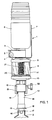
- the device according to the invention comprises a support frame 3, which can be fastened, for example, to a wall in a manner not known, because it is known, with a dovetail-shaped mounting bracket 5.
- the push-on bracket is designed with a counterpart attached to the wall as a clamp connection, which can be locked with a wing screw 4.
- a storage container 6 with a pouring opening pointing downward can be fastened to the support frame 3, preferably via a threaded connection.
- An intermediate store 8 is arranged on the side of the supporting frame facing away from the storage container 6.
- This essentially comprises a transparent, hollow cylindrical body 11, for example a sight glass, each of which is closed on its end faces with an upper flange 9 and a lower flange 10.
- the upper flange 9, which faces the support frame 3, has mechanical means for connection to the support frame.
- a shield 7 is provided between the upper flange 9 and the support frame 3, for example for attaching a product name.
- a mouthpiece 12 is provided on the lower flange 10.
- This essentially comprises a piston tube 14, on the end of which a first piston 15 is arranged facing away from the intermediate store 8 and the second end of which is essentially connected to a second piston 20 which is located in the intermediate store 8.
- the piston tube 14 is longitudinally displaceable within an end sleeve 13 which is attached to the lower flange 10.
- a spring 21 visible through the sight glass 11 for the second piston 20 essentially ensures the rest position of the mouthpiece 12 shown in FIG. 1.
- the refilling of a container 2 occurs essentially in that the container 2 is placed over an outflow pipe 16 which is only partially visible in this figure.
- the opening of the container to be refilled is in contact with a pressure flange 17 of the first piston 15.
- the first piston 15 is displaced longitudinally relative to the mouthpiece 12 or relative to the piston tube 14 until the pressure flange 17 abuts a piston tube flange 18.
- this movement leads to an outlet valve arranged on the outlet pipe 16 being opened.
- the piston tube 14 begins to extend into the intermediate store.
- the second piston 20 is moved toward the upper flange 9.
- the substance in the intermediate store is conveyed through this movement through a passage in the second piston 20 through the piston tube 14 and the outflow tube 16 into the container 2.
- the reservoir 6 is closed by a shutoff valve, which is not visible in this figure.
- the material is conveyed as long as the pressure movement of the container continues. This can be limited, for example in order to prevent the overfilling of a container, by means of a sleeve-shaped stop member 51 which is arranged on the end sleeve 13 so as to be longitudinally displaceable.
- the stop member 51 is essentially adjustable and lockable with a locking screw 52.
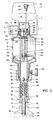
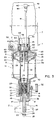
- FIGS. 2 and 3 the device according to the invention for refilling a container is shown as a sectional drawing once in the rest position (FIG. 2) and once each with the mouthpiece 12 fully pushed in (FIG. 3). Parts that have already been described with reference to FIG. 1 have the same reference numerals in FIGS. 2 and 3. 2 is the mechanical structure of the device according to the invention are described in more detail.
- the spout of the reservoir 6 is connected to the support frame 3 via a threaded connection 53.
- a ventilation pipe 41 projects into the storage container 6 and extends practically over the entire length of the storage container.
- the ventilation pipe 41 is connected at one end to a holding element 45 which is arranged in an inlet bush 46 of the support frame 3.
- the inlet bushing 46 extends in the longitudinal direction of the threaded connection 53, essentially adjoining it, but facing away from the storage container 6 and toward the intermediate store 8.
- the holding element 45 is designed, for example, in the form of an eye or web 49, which projects radially from the wall of the inlet bush 46 into the interior thereof.
- the web 49 covers approximately half, including the center, of the cross section of the inlet bush 46.
- a ventilation channel 50 forms the extension of the lower end of the mentioned ventilation pipe and extends within the holding element 45 to a ventilation hole (not visible in the drawing) in the support frame 3.
- the web 49 has a bore 54 in its center, the function of which will be explained further below.
- An aeration valve 42 is arranged at the end of the aeration tube 41 which is close to the upper end of the storage container 6.
- This essentially comprises a valve ball 44, which is held by a valve cap 43, which can be screwed onto the corresponding end of the ventilation pipe.
- the ventilation valve 42 works in such a way that, in the case of a negative pressure in the storage container 6, the valve ball 44 due to the normal air pressure in the ventilation pipe 41 is raised, whereby outside air can flow into the reservoir 6 through the path already mentioned.
- the intermediate store 8, in particular its upper flange 9, is connected to the support frame 3, for example, via a further, unspecified threaded connection.
- the upper flange 9 has essentially, like the lower flange 10, a plate-like shape. In the center of the two flanges there is an opening, which opens into a hollow cylindrical extension.
- the extension of the upper flange 9 is connected to the support frame 3 on its outside by the thread connection already mentioned, for example.
- the inlet bushing 46 is arranged on the inside of the extension and is sealed off from the upper flange 9 by means of an inlet bushing seal 47.
- Another, designated 55 seal which is arranged between the support frame 3 and the storage container 6, ensures the tight closure of the storage container 6 on the support frame 3.
- the aforementioned hollow cylindrical sight glass 11 is embedded in a groove of the plate-shaped upper flange 9, the aforementioned hollow cylindrical sight glass 11 is embedded.
- the lower flange 10 closes off the lower end face of this sight glass with an essentially identical groove.
- the end sleeve 13, which has also already been mentioned, is screwed onto the hollow-cylindrical extension of the lower flange 10, for example.
- the piston tube 14 is connected in the region of a lower stop end 19 of the end sleeve 13 (FIG. 2) to a connecting tube 30, which extends the piston tube 14 to the second piston 20, which is arranged within the intermediate store 8.
- the piston 20 is attached to the end of the connecting tube 30 facing away from the piston tube 14.
- the piston tube 14 and the connecting tube 30 are inside of the lower flange 10 and the end sleeve 13 are arranged so as to be longitudinally displaceable.
- the inner surface of the hollow-cylindrical extension of the lower flange 10 forms a first part of the bearing and the stop 19 designed as a bent end of the end sleeve 13 forms a further part of the bearing.
- the tightness is ensured by a piston tube seal 31 which is mounted between the piston tube 14 or connecting tube 30 and the end sleeve 13 in the region of the stop 19.
- the second piston 20 is also plate-shaped and essentially comprises on its periphery a piston seal 33, which seals the piston against the sealing glass 11, and a central bushing 35 arranged in the center of the piston Piston connected.
- the return spring 21 designed as a compression spring for the second piston 20 acts between the inlet bush 46 and the side of the piston 20 facing away from the piston tube 14.
- An annular seal 36 preferably an O-ring, is arranged in the central bush 35 mentioned. This can be compressed using a set screw 37.
- a towing rod 39 extends for a shut-off valve 22.
- One end of the towing rod 39 lies in the area of the central sleeve 35 when the device is at rest (FIG.
- the first piston 15 is arranged to be longitudinally movable within said piston tube 14.
- the first piston 15 has a central bore in which the outlet pipe 16, which extends away from the piston pipe 14, is fastened. Furthermore, the first piston 15 has a piston seal 32 in its area sliding within the piston tube 14.
- the end of the first piston 15 facing away from the piston tube 14 includes the abovementioned stop 17 for the container 2 to be refilled.
- the first, for example star-shaped, webs 29 has a further central bushing in the center Hold 56.
- An outlet valve 23 is arranged at the end of the outlet valve rod 27.
- This comprises a valve closure cone 25, which is connected to the outlet valve rod 27, and an outlet valve seal 26 attached to the valve closure cone 25.
- the end of the outlet pipe 16 facing away from the first piston 15 presses in the idle state, supported by an outlet valve spring 28 against the mentioned seal 26.
- the longitudinal mobility of the first piston 15 is in one case due to the abutting of said end of the outlet pipe 16 said seal 26 and in the other case by the contact of the pressure flange 17 against the piston tube flange 18, which, as already said, is located at the lower end of the piston tube 14.
- the outlet valve spring 28 is designed as a compression spring and acts between the end of the first piston 15 located in the piston tube 14 and a shoulder 57 which has been created in the region of the end of the piston tube 14 facing the connecting tube 30.
- the ring seal 36 in the central sleeve 35 is tightened so much with the set screw 37 that, due to the great friction, the drag rod 39 is carried along by the second piston 20 until the valve disk 38 of the closing valve 22 rests sealingly on the valve seat 40 of the inlet bush 46.
- the passage between the reservoir 6 and the intermediate storage 8 is now closed.
- the ring seal 36 thus acts, together with the set screw 37, as a second mechanical coupling means between the mouthpiece 12 and the shutoff valve 22.
- the viscous substance stored in the intermediate store 8 becomes between the star-shaped material as the piston 20 moves forward Holding member 34 of the second piston 20 through, the connecting tube 30, the piston tube 14, and the outflow pipe 16 transported into the container 2. This continues until either the second piston 20 is in contact with the upper flange 9 of the intermediate store 8 or until the piston tube flange 18 is in contact with the previously set stop member 51.
- the outlet valve spring 28 ensures that the outlet valve 23 is closed immediately.
- the second piston 20, which moves back relatively slowly due to the force of the return spring 21, provides for the opening of the closing valve 22 due to the frictional coupling between the O-ring 36 and the towing rod 39.
- the valve disk 38 is removed from the valve seat 40 until the locking washer 48 is at web 49.
- both the outlet valve 23 and the closing valve 22 are mechanically coupled to the container 2 to be refilled or to the mouthpiece 12, these valves become independent of the viscosity of the Always open or close the substance to be refilled. A complex and critical dimensioning or adjustment of the springs is not necessary. Even if the spring force varies widely, under the condition that the spring force of the exhaust valve spring 28 is smaller than the spring force of the return spring 21, the device functions properly without maintenance for a long period of time.
Landscapes
- Engineering & Computer Science (AREA)
- Mechanical Engineering (AREA)
- Health & Medical Sciences (AREA)
- Public Health (AREA)
- Containers And Packaging Bodies Having A Special Means To Remove Contents (AREA)
- Loading And Unloading Of Fuel Tanks Or Ships (AREA)
- Closures For Containers (AREA)
Applications Claiming Priority (2)
| Application Number | Priority Date | Filing Date | Title |
|---|---|---|---|
| CH3064/90A CH681447A5 (fr) | 1990-09-24 | 1990-09-24 | |
| CH3064/90 | 1990-09-24 |
Publications (2)
| Publication Number | Publication Date |
|---|---|
| EP0477773A2 true EP0477773A2 (fr) | 1992-04-01 |
| EP0477773A3 EP0477773A3 (en) | 1992-08-19 |
Family
ID=4247821
Family Applications (1)
| Application Number | Title | Priority Date | Filing Date |
|---|---|---|---|
| EP19910115919 Withdrawn EP0477773A3 (en) | 1990-09-24 | 1991-09-19 | Device and method for refilling a container with a more or less viscous substance |
Country Status (5)
| Country | Link |
|---|---|
| US (1) | US5224528A (fr) |
| EP (1) | EP0477773A3 (fr) |
| AU (1) | AU8468691A (fr) |
| CA (1) | CA2052127A1 (fr) |
| CH (1) | CH681447A5 (fr) |
Cited By (1)
| Publication number | Priority date | Publication date | Assignee | Title |
|---|---|---|---|---|
| CN102756814A (zh) * | 2012-07-31 | 2012-10-31 | 广州达意隆包装机械股份有限公司 | 一种灌装机的中心分配器 |
Families Citing this family (9)
| Publication number | Priority date | Publication date | Assignee | Title |
|---|---|---|---|---|
| WO1997047557A1 (fr) * | 1996-06-11 | 1997-12-18 | Morrison Walter | Pistolet distributeur de fluide |
| US5839623A (en) * | 1996-07-29 | 1998-11-24 | Pure Vision International, L.L.P. | Reusable pressure spray container |
| US5865350A (en) * | 1997-01-24 | 1999-02-02 | Pure Vision International L.L.P. | Spray bottle with built-in pump |
| US5921439A (en) * | 1998-01-26 | 1999-07-13 | Pure Vision International L.L.P. | Aerosol spray container with improved dispensing valve assembly |
| US5957333A (en) * | 1998-01-26 | 1999-09-28 | Pure Vision International L.L.P. | Aerosol spray container with improved dispensing valve assembly |
| US6484765B1 (en) * | 2000-12-18 | 2002-11-26 | Kody Clemmons | Fast flowing spring loaded valve assembly |
| US6662828B1 (en) * | 2001-05-22 | 2003-12-16 | Clifford W. Stover | Telescoping filling head |
| US7841492B2 (en) * | 2007-07-16 | 2010-11-30 | Rodney Laible | Anti-drip valve for a dispensing and/or dosing system |
| US10889486B1 (en) * | 2020-09-01 | 2021-01-12 | Rodney Laible | Dispensing and/or dosing system |
Family Cites Families (23)
| Publication number | Priority date | Publication date | Assignee | Title |
|---|---|---|---|---|
| FR1093327A (fr) * | 1955-05-03 | |||
| US689468A (en) * | 1901-03-20 | 1901-12-24 | John P Dobbyn | Measuring-faucet. |
| FR337616A (fr) * | 1903-12-12 | 1904-04-18 | L Antoine Et Cie Soc | Dispositif permettant d'introduire dans des bouteilles ou récipients quelconques une quantité de liquide constante |
| US966270A (en) * | 1909-08-20 | 1910-08-02 | S S Wenzell Machine Company | Bottle-filling machine. |
| US1068067A (en) * | 1911-11-27 | 1913-07-22 | John Mcpherson Jr | Liquid-dispensing apparatus. |
| US1335800A (en) * | 1918-11-21 | 1920-04-06 | Le Roy M Smith | Automatic liquid-measuring appliance |
| US1837412A (en) * | 1927-09-19 | 1931-12-22 | Sprague Sells Corp | Filling valve |
| US1763971A (en) * | 1927-10-21 | 1930-06-17 | Kantor James | Dispensing device |
| GB448756A (en) * | 1935-11-15 | 1936-06-15 | Clifford Brunswick Harley | Improved filling heads for bottling machines |
| CH203102A (de) * | 1937-02-03 | 1939-02-28 | Non Drip Measure Co Ltd | Vorrichtung zur Abgabe abgemessener Flüssigkeitsmengen. |
| US2168380A (en) * | 1937-10-07 | 1939-08-08 | American Sealcone Corp | Container filling apparatus |
| US2601359A (en) * | 1946-07-02 | 1952-06-24 | Gaskell & Chambers Ltd | Takedown liquid measuring dispenser having resiliently connected inlet and outlet valves |
| GB676096A (en) * | 1948-07-16 | 1952-07-23 | Churchill Henry Winston S | Improvements relating to apparatus for dispensing pastes, liquids and other substances |
| US2652965A (en) * | 1948-12-20 | 1953-09-22 | King Sales & Engineering Co | Liquid filling valve |
| FR1022067A (fr) * | 1950-07-13 | 1953-02-27 | Poste d'emplissage de récipients par dosage de la quantité de liquide délivrée dans lesdits récipients | |
| US2820579A (en) * | 1954-02-11 | 1958-01-21 | Pfaudler Co Inc | Combined valve and measuring chamber |
| GB805905A (en) * | 1955-09-03 | 1958-12-17 | Machf V H Jansen & Sutorius Nv | Improvements in and relating to discharge valves adapted to be mounted at the bottomof a receptacle for liquids |
| US4210262A (en) * | 1978-07-10 | 1980-07-01 | Peter Donaldson | Liquid dispensing apparatus with vent valve |
| FR2542300A1 (fr) * | 1983-03-11 | 1984-09-14 | Vidal Jacques | Verseur-doseur |
| GB8507868D0 (en) * | 1985-03-26 | 1985-05-01 | Salesprint Temple Group Ltd | Liquid dispenser |
| FR2621897B1 (fr) * | 1987-10-14 | 1990-02-09 | Smt | Distributeur automatique de produits pateux |
| DE3910066C2 (de) * | 1988-08-18 | 1997-10-02 | Thomas Peter | Vorrichtung zur Portionierung und Abgabe von fließfähigen Medien |
| CH679335A5 (en) * | 1989-11-01 | 1992-01-31 | Schwarzkopf Hans Ag | Fluid metering device for portion dispensing - has intermediate store with simultaneously-controlled discharged line and vent line |
-
1990
- 1990-09-24 CH CH3064/90A patent/CH681447A5/de not_active IP Right Cessation
-
1991
- 1991-09-19 EP EP19910115919 patent/EP0477773A3/de not_active Withdrawn
- 1991-09-24 CA CA002052127A patent/CA2052127A1/fr not_active Abandoned
- 1991-09-24 AU AU84686/91A patent/AU8468691A/en not_active Abandoned
- 1991-09-24 US US07/764,720 patent/US5224528A/en not_active Expired - Fee Related
Cited By (1)
| Publication number | Priority date | Publication date | Assignee | Title |
|---|---|---|---|---|
| CN102756814A (zh) * | 2012-07-31 | 2012-10-31 | 广州达意隆包装机械股份有限公司 | 一种灌装机的中心分配器 |
Also Published As
| Publication number | Publication date |
|---|---|
| US5224528A (en) | 1993-07-06 |
| CH681447A5 (fr) | 1993-03-31 |
| EP0477773A3 (en) | 1992-08-19 |
| AU8468691A (en) | 1992-03-26 |
| CA2052127A1 (fr) | 1992-03-25 |
Similar Documents
| Publication | Publication Date | Title |
|---|---|---|
| DE2953673T1 (de) | Manuelle Flussigkeits-Abgabevorrichtung | |
| DE2308460A1 (de) | Ventil | |
| EP0477773A2 (fr) | Dispositif et méthode pour remplir un réservoir avec une substance plus ou moins visqueuse | |
| WO1998043012A2 (fr) | Presse destinee a comprimer des lubrifiants et cartouche utilisee a cet effet | |
| DE2438796C2 (de) | Vorrichtung zum portionsweisen Abfüllen von flüssigem oder pastösem Füllgut in Behältnisse | |
| EP1830965A1 (fr) | Dispositif permettant l'ecoulement dose d'un fluide | |
| DE3152153A1 (en) | Improvement in self-closing closures | |
| EP2428485A1 (fr) | Buse de distribution | |
| DE1648129B1 (de) | Dosiervorrichtung zur abgabe von fluessigkeiten aus einer unter druck stehenden quelle an eine verbraucherstelle | |
| DE2416286A1 (de) | Selbstschliessende armatur | |
| EP0637711B1 (fr) | Vanne pour fluides | |
| DE3616990C1 (de) | Luftstossgeraet zur Aufloesung von Materialaufstauungen in Lagersilos fuer Schuettgut | |
| DE2831463A1 (de) | Spuelvorrichtung fuer eine getraenke- entnahme-anlage | |
| DE3509720A1 (de) | Rohrtrenner | |
| DE3933754C2 (fr) | ||
| DE60302566T2 (de) | Fluidproduktabgabepumpe | |
| DE3212089A1 (de) | Ventil | |
| DE2107647A1 (de) | Vorrichtung zum Verhindern des Nachtropfens bei einer Abfüllanlage | |
| DE1761313A1 (de) | Gegendruck-Ventilvorrichtung fuer einen Kreislauf zur Speisung einer Maschine fuer die keimfreie Verpackung von Fluessigkeiten | |
| WO1989001879A1 (fr) | Raccord a visser dans l'ouverture d'un recipient | |
| EP0290048A2 (fr) | Pompe doseuse pour liquides épais | |
| DE2408718A1 (de) | Dosiervorrichtung fuer eine duschanlage | |
| DE2619061A1 (de) | Druckregler fuer eine druckluftspeicheranlage | |
| DE2936056C2 (de) | Dosiervorrichtung für Flüssigkeiten | |
| DE244331C (fr) |
Legal Events
| Date | Code | Title | Description |
|---|---|---|---|
| PUAI | Public reference made under article 153(3) epc to a published international application that has entered the european phase |
Free format text: ORIGINAL CODE: 0009012 |
|
| AK | Designated contracting states |
Kind code of ref document: A2 Designated state(s): AT BE DE DK ES FR GB GR IT LU NL SE |
|
| PUAL | Search report despatched |
Free format text: ORIGINAL CODE: 0009013 |
|
| AK | Designated contracting states |
Kind code of ref document: A3 Designated state(s): AT BE DE DK ES FR GB GR IT LU NL SE |
|
| 17P | Request for examination filed |
Effective date: 19921208 |
|
| 17Q | First examination report despatched |
Effective date: 19940517 |
|
| STAA | Information on the status of an ep patent application or granted ep patent |
Free format text: STATUS: THE APPLICATION IS DEEMED TO BE WITHDRAWN |
|
| 18D | Application deemed to be withdrawn |
Effective date: 19951031 |