EP0478248A2 - Elektrischer Adapterstecker - Google Patents
Elektrischer Adapterstecker Download PDFInfo
- Publication number
- EP0478248A2 EP0478248A2 EP91308621A EP91308621A EP0478248A2 EP 0478248 A2 EP0478248 A2 EP 0478248A2 EP 91308621 A EP91308621 A EP 91308621A EP 91308621 A EP91308621 A EP 91308621A EP 0478248 A2 EP0478248 A2 EP 0478248A2
- Authority
- EP
- European Patent Office
- Prior art keywords
- plug
- fuse
- insert
- adapter plug
- contact
- Prior art date
- Legal status (The legal status is an assumption and is not a legal conclusion. Google has not performed a legal analysis and makes no representation as to the accuracy of the status listed.)
- Ceased
Links
- 239000004020 conductor Substances 0.000 claims description 10
- 230000013011 mating Effects 0.000 claims description 10
- 235000019504 cigarettes Nutrition 0.000 abstract description 4
- 238000003780 insertion Methods 0.000 abstract description 3
- 230000037431 insertion Effects 0.000 abstract description 3
- 230000014759 maintenance of location Effects 0.000 description 11
- 230000003247 decreasing effect Effects 0.000 description 3
- 238000004519 manufacturing process Methods 0.000 description 2
- 230000004044 response Effects 0.000 description 2
- 230000009471 action Effects 0.000 description 1
- 230000000712 assembly Effects 0.000 description 1
- 238000000429 assembly Methods 0.000 description 1
- 230000000994 depressogenic effect Effects 0.000 description 1
- 230000008439 repair process Effects 0.000 description 1
- 230000035939 shock Effects 0.000 description 1
Images

Classifications
-
- H—ELECTRICITY
- H01—ELECTRIC ELEMENTS
- H01R—ELECTRICALLY-CONDUCTIVE CONNECTIONS; STRUCTURAL ASSOCIATIONS OF A PLURALITY OF MUTUALLY-INSULATED ELECTRICAL CONNECTING ELEMENTS; COUPLING DEVICES; CURRENT COLLECTORS
- H01R24/00—Two-part coupling devices, or either of their cooperating parts, characterised by their overall structure
- H01R24/58—Contacts spaced along longitudinal axis of engagement
-
- H—ELECTRICITY
- H01—ELECTRIC ELEMENTS
- H01R—ELECTRICALLY-CONDUCTIVE CONNECTIONS; STRUCTURAL ASSOCIATIONS OF A PLURALITY OF MUTUALLY-INSULATED ELECTRICAL CONNECTING ELEMENTS; COUPLING DEVICES; CURRENT COLLECTORS
- H01R13/00—Details of coupling devices of the kinds covered by groups H01R12/70 or H01R24/00 - H01R33/00
- H01R13/66—Structural association with built-in electrical component
- H01R13/68—Structural association with built-in electrical component with built-in fuse
Definitions
- This invention relates to an electrical adapter plug which may be inserted into the sockets or receptacles of automobile cigarette lighter assemblies so that various low voltage loads may be operated by the electrical system of the vehicle.
- existing adapter plug designs each have one or two spring contacts mating with a receptacle sleeve. If there are two contacts, they are usually angularly spaced to project from the periphery of an adapter plug body at an angle of 180°. Accordingly, the vector sum of the mechanical forces of two contacts within the sleeve are in-line or 180° opposing and there is zero force on the body of the adapter plug to position it against the receptacle surface.
- the adapter plug is able to pivot on the in-line contact points within the receptacle. When the adapter plug is free to pivot more, it can loosen and eventually lose electrical contact when subject to vibration or shock.
- U.S. Patent 4,988,315 in the name of the present Applicants discloses a novel electrical adapter plug design having a pair of spaced electrical spring contacts located on the periphery of an adapter plug body. These contacts cooperate with a diametrically opposite groove in a first preferred embodiment to establish improved mating contact with the cylindrical sleeve of a cigarette lighter receptacle when the adapter plug is manually inserted into the receptacle.
- the adapter plug makes contact with the sleeve of the receptacle in four areas, namely, the two lines which define the two edges of the groove and the two spring contact points. This four area mating contact between the adapter plug and its receptacle greatly improves the retention of the adapter plug in the receptacle.
- An ideal adapter plug design would require the same optimum force (or from an equivalent viewpoint the same resistance to withdrawal) without regard to the bore size of the receptacle.
- the difficulty in attaining this ideal force requirement is explained in part by noting that for cigarette lighter receptacles, the largest European size is approximately 0.890 inch I.D. (22.6 mm) and the smallest U.S. receptacle has a 0.824 inch I.D. (20.9 mm). If a single size adapter plug could be designed having a narrow range of retention forces and also withdrawal forces for various size receptacles, manufacturing economies would ensue.
- a principal object of this invention is to provide an electrical adapter plug for which the forces of retention and also withdrawal have a relatively narrow range when a single-size adapter plug is used with different receptacles having a wide range of bore sizes.
- Another object is to attain economies of cost, manufacture and inventory by providing a single size electrical adapter plug for different receptacles having a wide range of bore sizes.
- an elongate electrical adapter plug having a pair of retractable leaf-spring contacts angularly spaced about the periphery of the adapter plug in the range of about 20° to 150°, the plug being insertable into the bore of a mating receptacle to establish electrical contact between at least one of the contacts and the receptacle, the plug including a pair of elongate body halves ,defining an internal cavity arranged to house a fuse, characterised by a fuse insert located within the body cavity to form a socket for the fuse and also to form a locking element to which each body half is separately joined.
- the fuse insert is generally elongate and has a longitudinal axis generally aligned with the longitudinal axis of the elongate adapter plug.
- the fuse insert is conveniently part of a lock which includes a mechanical fastener joining only one body half to the fuse insert.
- the lock may also include a pair of projecting locking fingers which are an integral part of the fuse insert and which engage and join the other body half.
- the said other body half may have a locking tongue having two holes which engage the locking fingers.
- the fuse insert may be a pleated conductor located at least in part within the fuse insert to engage and position the fuse.
- the fuse insert serves as a support for one of the leaf-spring contacts.
- the adapter plug body features a novel fuse insert captured between the two housing halves which are held together by, for example, a single screw engaging the fuse insert.
- the fuse insert may serve as a support for two long leaf-spring contacts and the conventional tubular fuse associated with the positive adapter-plug tip contact.
- the leaf-spring contacts may extend the length of the insert.
- the insert can be used to latch into one of the housing halves thereby holding the two body halves together.
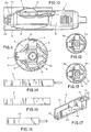
- An important feature of the present invention concerns a fuse insert 4 (Figure 17) located within the central cavity defined by body halves 5 and 6.
- a fuse insert 4 ( Figure 17) located within the central cavity defined by body halves 5 and 6.
- the insert 4 latches onto one of the body halves thereby holding the two body halves together as well as providing a chamber for containing the fuse 7.
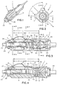
- the included angle A ( Figure 2) must be less than 180°, and preferably the angle should be in the range of about 20° to 150°.
- the angle A is about 90°. As this angle is increased to greater than 90°, the resultant force vector V Figure 2 exerted against the line edges 9 and 10 is decreased, and as this angle is decreased, the vector V is increased. However, in both cases, a substantial deviation in angle A from 90° enables the adapter plug 1 to pivot more easily due to decreased retention.
- the groove 8 is optimally located on the periphery of the adapter plug 1 generally opposite the electrical leaf-spring contacts 2 and 3 so as to be centred on a force line V which represents an extension of the resultant force vector generated by the two spring contacts 2 and 3 when mated with the receptacle 12.
- the groove 8 is generally aligned lengthwise with the longitudinal axis of the plug.
- the adapter plug 1 is also formed with two joined plastic body halves 5a and 6a.
- the periphery of the resulting plug body omits the groove 8 of the first embodiment and is contoured to define an elongate projection 11 generally aligned lengthwise with the longitudinal axis of the plug.
- three distinct areas of mating contact are established between the adapter plug 1 and receptacle 12.
- point contacts are established by the leaf-spring contacts 2 and 3 and a single line contact is formed by the elongate projection 11.
- the retention provided by the elongate projection 11 is somewhat less than that provided by the groove 8, but it is satisfactory for applications not involving vibration.
- FIG. 13 A second alternative to the groove 8 is shown in the cross-sectional view of Figure 13.
- the adapter plug 1 is again formed with two joined plastic body sections 5b and 6b.
- the body section 6b is formed with a flat portion 13 defined by two elongate line edges 14 and 15. These edges are aligned with the longitudinal axis of the adapter plug.
- the edges 14 and 15 make two line contact with the receptacle 12 when the adapter plug 11 is inserted within the receptacle 12.
- the four area contact provided by the embodiment of Figure 13 functions to provide plug retention in a manner which is essentially identical to that provided by the groove edges 9 and 10.
- the adapter plug design should employ angularly spaced point contacts effected by at least a pair of retractable spring contacts. These point contacts must cooperate with one or two line contacts located either generally on (in the case of one line), or in the case of two spaced lines preferably symmetrically disposed, with respect to a diametrically extended line which bisects the angle between the two spaced contacts. This extended line also represents the resultant force vector generated by the two spring contacts.
- plastic body halves 5 and 6 define an internal cavity which houses a plastic fuse insert 4 (Figure 17).
- the body half 5 is appropriately designated the male half because it is formed with an integral riblike locking tongue 16 (Figure 8) which projects into the portion of the internal cavity defined by the female body half 6.
- the locking tongue 16 has two aligned rectangular holes 17 and 18 which are engaged by a mating pair of latching fingers 19 and 20 ( Figure 17) which project from the right-hand end of the tubular insert 4.
- This insert end also contains a threaded hole 21 ( Figures 4 and 9) which receives a plastic fastening screw 22 which passes through a recessed hole 23 formed in the female body half 6. Accordingly, the engagement of the locking tongue 16 by latching fingers 19 and 20, and thus the body halves 5 and 6, fastens together the cord 24 end of adapter plug 1.
- adapter plug 1 containing a positive contact tip 25 is fastened together by a metallic flanged holding ring 26 which is tightly seated on the semi-circular ends 27 and 28 of the body halves 5 and 6 by a threaded tip retainer 29.
- a tubular fuse 7 is partially lodged between spaced insert walls 30 and 31, and is sandwiched between the positive contact tip 25 and a pleated positive conductor 32.
- the pleated section of the conductor 32 serves as a biasing spring to project the positive contact tip 25 outwards.
- the contact tip 25 is retracted into the adapter plug 1 when the plug is inserted into the receptacle 12 ( Figure 9). This action compresses the pleated section of the conductor 32, enabling the fuse 7 to move deeper into the insert 4.
- the leaf-spring contacts 2 and 3 have very long flexing body sections which depress relative to the body of the adapter plug 1 in response to plug insertion into the receptacle 12.
- the leaf-spring contact 3 is the active negative contact of the plug 1 because of its direct connection to a negative line conductor 33 ( Figure 3), while the pleated positive conductor 32 is also active because of its direct connection to a positive line conductor 34.
- the leaf-spring contact 2 is a dummy or inactive negative contact because in the particular embodiment shown in the drawing, it is a "free-floating" contact which is not connected to any line conductor. If desired, however, the contact 2 could be made an active contact simply by connecting it to the contact 3 or the line conductor 33.
- the active leaf-spring contact 3 has a flexing portion L ( Figure 3) consisting of an arched section E (exposed) projecting through a body rectangular slot 35 and a relatively flat section C (confined) lodged within the interior body cavity 36.
- section E is approximately 0.740 ⁇ (18.8 mm) long
- section C is approximately 0.880 ⁇ (22.4 mm) long.
- the contact 3 is formed with an anchor tip 37 that is anchored into a mating recess formed in the male body half 5 and the opposite end of the contact 3 is formed with a non-flexing support section 38 that is curved to pass below a rib 39 and is motion restrained by a rib 40.
- the active leaf-spring contact 3 assumes the distorted depressed contour shown in Figure 9 in response to insertion of the adapter plug 1 into the receptacle 12.
- the inactive (dummy) leaf-spring contact 2 is formed with dimensions L, E and C ( Figure 4) that are identical to the dimensions L, E and C respectively, for the active contact 3.
- the contact 2 is formed with an anchor tip 41 that is anchored into a mating recess defined by the body 5 and an insert support projection 42 ( Figures 4 and 7) cantilevered from an insert case 43.
- the opposite end 45 of the contact 2 is restrained by an insert support projection 44 ( Figure 4) and the body half 5.
- the leaf-spring contacts 2 and 3 are relatively long with respect to the body of adapter plug 1 (which is 2.76 inches (70.1 mm) long in a preferred commercial embodiment), the forces of plug retention and also withdrawal have a relatively narrow range when a single-size adapter plug is used with different receptacles having a wide range of bore sizes.
- the (dummy) leaf-spring contact 2 could only extend to line D, L, ( Figure 4), otherwise the contact 2 would interfere with a long screw (not shown) which would join the body halves 5 and 6. This screw would be located on the same axis as the fastening screw 22.
Landscapes
- Details Of Connecting Devices For Male And Female Coupling (AREA)
Applications Claiming Priority (2)
| Application Number | Priority Date | Filing Date | Title |
|---|---|---|---|
| US586998 | 1990-09-24 | ||
| US07/586,998 US5131869A (en) | 1990-09-24 | 1990-09-24 | Electrical adapter plug |
Publications (2)
| Publication Number | Publication Date |
|---|---|
| EP0478248A2 true EP0478248A2 (de) | 1992-04-01 |
| EP0478248A3 EP0478248A3 (en) | 1992-08-19 |
Family
ID=24347908
Family Applications (1)
| Application Number | Title | Priority Date | Filing Date |
|---|---|---|---|
| EP19910308621 Ceased EP0478248A3 (en) | 1990-09-24 | 1991-09-23 | Electrical adaptor plug |
Country Status (2)
| Country | Link |
|---|---|
| US (1) | US5131869A (de) |
| EP (1) | EP0478248A3 (de) |
Cited By (1)
| Publication number | Priority date | Publication date | Assignee | Title |
|---|---|---|---|---|
| CN109341901A (zh) * | 2018-10-29 | 2019-02-15 | 深圳市通意达机电设备有限公司 | 压力检测仪 |
Families Citing this family (19)
| Publication number | Priority date | Publication date | Assignee | Title |
|---|---|---|---|---|
| USD349098S (en) | 1992-12-01 | 1994-07-26 | Flying Dragon Development Limited | Electric plug |
| US5326283A (en) * | 1993-08-03 | 1994-07-05 | E Lead Electronic Co., Ltd. | Electrical plug for automobile use |
| US5421058A (en) * | 1993-10-01 | 1995-06-06 | Royal Appliance Mfg. Co. | Hand-held vacuum cleaner |
| US5569053A (en) * | 1994-09-08 | 1996-10-29 | Andrew Corporation | Connector for connecting an electronic device to a vehicle electrical system |
| US5775952A (en) * | 1995-09-20 | 1998-07-07 | Lu; Wen-San | Plug for automobile cigarette lighter socket |
| US5964623A (en) * | 1998-01-29 | 1999-10-12 | Andrew Corporation | Easily gripped cigarette lighter adapter with balanced, solderless ground contacts |
| SE522773C2 (sv) * | 1998-06-29 | 2004-03-02 | Ericsson Telefon Ab L M | Anpassningsbar stickpropp för uttag med olika djup och diameter |
| TW509641B (en) * | 1999-04-09 | 2002-11-11 | Primax Electronics Ltd | Automotive electrical appliances supporting device |
| DE20004394U1 (de) * | 2000-03-09 | 2000-08-03 | Tsay, Wen-Feng, Taipeh/T'ai-pei | Anschlussstück für Zigarettenzünder |
| US6368157B1 (en) * | 2001-04-09 | 2002-04-09 | Joseph Bottazzi, Jr. | Adapter for connecting various electronic devices to a cigarette accessory socket |
| US6394851B1 (en) | 2001-06-28 | 2002-05-28 | Andrew Corporation | Cigarette lighter adapter with one-piece solderless ground contact |
| US6609931B2 (en) * | 2001-10-25 | 2003-08-26 | Tyco Electronics Corp. | Orientationless squib connector assembly |
| AU2003212726A1 (en) * | 2002-02-18 | 2003-09-04 | Derrick Arthur Bishop | Vehicle data logging systems |
| US6752649B2 (en) * | 2002-11-07 | 2004-06-22 | Xentris, Llc | Illuminated indicia power supply apparatus and method of manufacture |
| US7238058B1 (en) * | 2006-01-26 | 2007-07-03 | French Vernon E | Grounding plug |
| US8162683B2 (en) | 2010-05-13 | 2012-04-24 | Advanced Bionics, Llc | Miniature electrical connectors |
| US10583514B2 (en) * | 2015-09-18 | 2020-03-10 | Illinois Tool Works Inc. | Contact tip rotary lock of a welding torch |
| US12291945B1 (en) | 2019-03-05 | 2025-05-06 | Swm International, Llc | Downhole perforating gun system |
| US11078762B2 (en) | 2019-03-05 | 2021-08-03 | Swm International, Llc | Downhole perforating gun tube and components |
Family Cites Families (13)
| Publication number | Priority date | Publication date | Assignee | Title |
|---|---|---|---|---|
| US1151800A (en) * | 1914-01-28 | 1915-08-31 | Charles J Klein | Lamp-socket. |
| DE693054C (de) * | 1937-12-12 | 1940-07-01 | Jung Albrecht Fa | Elektrischer Stecker, insbesondere zur Verwendung bei Rundfunkanlagen |
| CH209441A (de) * | 1939-05-25 | 1940-04-15 | Feller Ag Adolf | Dreipolige Steckvorrichtung. |
| US2489037A (en) * | 1946-03-22 | 1949-11-22 | Peerless Tool & Engineering Co | Plug for automobile trouble lamp |
| US2954544A (en) * | 1957-07-22 | 1960-09-27 | Joseph W Focosi | Electrical plug connectors |
| US3099505A (en) * | 1961-08-16 | 1963-07-30 | Cable Electric Products Inc | Electrical connector |
| US3377610A (en) * | 1966-09-30 | 1968-04-09 | Busch | Plug for electrical cord |
| US3865463A (en) * | 1973-11-12 | 1975-02-11 | Busch & Co Inc Ag | Electrical adapter plug |
| US4322122A (en) * | 1980-04-11 | 1982-03-30 | Schwartz Edwin L | Cigarette lighter plug assembly |
| DE3035378A1 (de) * | 1980-09-19 | 1982-05-06 | INSTA Elektro GmbH & Co KG, 5880 Lüdenscheid | Elektrischer stecker fuer autosteckdosen und/oder auto-zigarrenanzuender |
| US4679884A (en) * | 1986-05-07 | 1987-07-14 | Litton Systems, Inc. | Fused electrical plug |
| JPS6457580A (en) * | 1987-08-26 | 1989-03-03 | Matsushita Electric Industrial Co Ltd | Cigar plug device |
| US4988315A (en) * | 1990-02-21 | 1991-01-29 | Safco Corporation | Electrical adapter plug |
-
1990
- 1990-09-24 US US07/586,998 patent/US5131869A/en not_active Expired - Lifetime
-
1991
- 1991-09-23 EP EP19910308621 patent/EP0478248A3/en not_active Ceased
Cited By (1)
| Publication number | Priority date | Publication date | Assignee | Title |
|---|---|---|---|---|
| CN109341901A (zh) * | 2018-10-29 | 2019-02-15 | 深圳市通意达机电设备有限公司 | 压力检测仪 |
Also Published As
| Publication number | Publication date |
|---|---|
| EP0478248A3 (en) | 1992-08-19 |
| US5131869A (en) | 1992-07-21 |
Similar Documents
| Publication | Publication Date | Title |
|---|---|---|
| EP0478248A2 (de) | Elektrischer Adapterstecker | |
| CA1301875C (en) | Floating panel mount for electrical connector | |
| US5073042A (en) | Coupling bushing for various types of optical fiber connectors | |
| EP0891644B1 (de) | Verriegelungsvorrichtung für einen steckverbinder | |
| US4639061A (en) | Environmentally sealed connector | |
| US5387127A (en) | Shielding device for T-type BNC connectors | |
| KR930024224A (ko) | 광섬유 컨넥터 | |
| US6648681B2 (en) | Connector with retainer members attachable to panel from either front or back wall face thereof and method of attaching the connector to the panel | |
| CA2205742A1 (en) | Connector for airbag gas generator | |
| US5934921A (en) | Power supply and the joint structure of adaptor plug thereof | |
| US4531801A (en) | Plug and receptacle connector locking means | |
| US4988315A (en) | Electrical adapter plug | |
| US6074236A (en) | Guide post structure of electrical connector | |
| US5651704A (en) | Electrical connector with terminal retainer | |
| US4304457A (en) | Electrical connector | |
| US20040087202A1 (en) | Slotted guide pin and latch assembly | |
| USRE34430E (en) | Floating panel mount for electrical connector | |
| US5306173A (en) | Bulb socket | |
| JPH01294383A (ja) | コネクタハウジング | |
| US5800199A (en) | Connector alignment guide | |
| EP0996009B1 (de) | Verbindungssystem für optische Faser Kontaktsteckverbinder | |
| US6634096B1 (en) | Terminal removal jig | |
| US4725242A (en) | Electrical connector having cam actuated wire holding means | |
| KR101802738B1 (ko) | 정션박스의 케이블 커넥터 연결구조 | |
| CN223884690U (zh) | 连接器的插座及连接器 |
Legal Events
| Date | Code | Title | Description |
|---|---|---|---|
| PUAI | Public reference made under article 153(3) epc to a published international application that has entered the european phase |
Free format text: ORIGINAL CODE: 0009012 |
|
| AK | Designated contracting states |
Kind code of ref document: A2 Designated state(s): DE FR GB |
|
| PUAL | Search report despatched |
Free format text: ORIGINAL CODE: 0009013 |
|
| AK | Designated contracting states |
Kind code of ref document: A3 Designated state(s): DE FR GB |
|
| 17P | Request for examination filed |
Effective date: 19930122 |
|
| 17Q | First examination report despatched |
Effective date: 19940623 |
|
| STAA | Information on the status of an ep patent application or granted ep patent |
Free format text: STATUS: THE APPLICATION HAS BEEN REFUSED |
|
| 18R | Application refused |
Effective date: 19941217 |