EP0478295B1 - Verfahren und Vorrichtung zur Herstellung eines Tragegriffes und eine Schachtel mit einem solchen Tragegriff - Google Patents
Verfahren und Vorrichtung zur Herstellung eines Tragegriffes und eine Schachtel mit einem solchen Tragegriff Download PDFInfo
- Publication number
- EP0478295B1 EP0478295B1 EP91308727A EP91308727A EP0478295B1 EP 0478295 B1 EP0478295 B1 EP 0478295B1 EP 91308727 A EP91308727 A EP 91308727A EP 91308727 A EP91308727 A EP 91308727A EP 0478295 B1 EP0478295 B1 EP 0478295B1
- Authority
- EP
- European Patent Office
- Prior art keywords
- box
- tape
- handle
- sealing tape
- box sealing
- Prior art date
- Legal status (The legal status is an assumption and is not a legal conclusion. Google has not performed a legal analysis and makes no representation as to the accuracy of the status listed.)
- Expired - Lifetime
Links
- 238000000034 method Methods 0.000 title claims description 16
- 238000007789 sealing Methods 0.000 claims description 155
- 239000000463 material Substances 0.000 claims description 89
- 239000000853 adhesive Substances 0.000 claims description 78
- 230000001070 adhesive effect Effects 0.000 claims description 78
- 230000007246 mechanism Effects 0.000 claims description 65
- 238000005452 bending Methods 0.000 claims 1
- 238000000926 separation method Methods 0.000 claims 1
- 239000002390 adhesive tape Substances 0.000 description 6
- 239000012190 activator Substances 0.000 description 5
- 239000004820 Pressure-sensitive adhesive Substances 0.000 description 2
- 230000004913 activation Effects 0.000 description 2
- 230000007812 deficiency Effects 0.000 description 2
- 230000014759 maintenance of location Effects 0.000 description 2
- 230000001360 synchronised effect Effects 0.000 description 2
- 238000004804 winding Methods 0.000 description 2
- 230000001934 delay Effects 0.000 description 1
- 238000007730 finishing process Methods 0.000 description 1
- 238000004519 manufacturing process Methods 0.000 description 1
- 238000005065 mining Methods 0.000 description 1
- 238000012856 packing Methods 0.000 description 1
- 230000001960 triggered effect Effects 0.000 description 1
Images





Classifications
-
- B—PERFORMING OPERATIONS; TRANSPORTING
- B65—CONVEYING; PACKING; STORING; HANDLING THIN OR FILAMENTARY MATERIAL
- B65D—CONTAINERS FOR STORAGE OR TRANSPORT OF ARTICLES OR MATERIALS, e.g. BAGS, BARRELS, BOTTLES, BOXES, CANS, CARTONS, CRATES, DRUMS, JARS, TANKS, HOPPERS, FORWARDING CONTAINERS; ACCESSORIES, CLOSURES, OR FITTINGS THEREFOR; PACKAGING ELEMENTS; PACKAGES
- B65D5/00—Rigid or semi-rigid containers of polygonal cross-section, e.g. boxes, cartons or trays, formed by folding or erecting one or more blanks made of paper
- B65D5/42—Details of containers or of foldable or erectable container blanks
- B65D5/44—Integral, inserted or attached portions forming internal or external fittings
- B65D5/46—Handles
- B65D5/46008—Handles formed separately from the container body
- B65D5/46016—Straps used as handles fixed to the container by glueing, stapling, heat-sealing
-
- B—PERFORMING OPERATIONS; TRANSPORTING
- B65—CONVEYING; PACKING; STORING; HANDLING THIN OR FILAMENTARY MATERIAL
- B65B—MACHINES, APPARATUS OR DEVICES FOR, OR METHODS OF, PACKAGING ARTICLES OR MATERIALS; UNPACKING
- B65B61/00—Auxiliary devices, not otherwise provided for, for operating on sheets, blanks, webs, binding material, containers or packages
- B65B61/14—Auxiliary devices, not otherwise provided for, for operating on sheets, blanks, webs, binding material, containers or packages for incorporating, or forming and incorporating, handles or suspension means in packages
Definitions
- the present invention relates to a method and device for forming a handle constructed of adhesive-coated tape to objects such as boxes, and to boxes having such a tape handle.
- a carrying handle can be designed from adhesive tapes.
- An example of a tape handle applied after a box has already been sealed is seen in Blank et al.
- U.S. Patent No. 3,031,359 which discloses a box in accordance with the preamble of claim 20.
- An example of a device which forms a tape handle on a box is disclosed in Gunther PCT/US88/01505 (WO 88/08812).
- the Blank et al. patent describes a pressure-sensitive adhesive tape handle for carrying packages consisting of a filament tape having a sheet material base of paper or other material. The tape handle is applied to the box after the box has been sealed.
- the Gunther PCT/US88/01505 patent describes a process for application of a carrying grip or handle by means of adhesive tape to a row of continuously moving cartons during automatic packing and sealing operations.
- the adhesive side of an excess length of the adhesive tape is covered or masked automatically with a cover tape in an operational step which is synchronized with the application of the adhesive tape to the carton.
- operational step which is synchronized with the application of the adhesive tape to the carton.
- Examples of devices for applying adhesive coated tape are described in Collet et al. U.S. Patent 3,915,786, Patterson U.S. Patent 3,954,550, and Deering, Jr. U.S. Patent 4,238,269. Such devices are commonly used to seal boxes filled with merchandise.
- the boxes are driven past the device by a conveyor.
- These devices include an application member such as a roller for supporting an end of the tape with the adhesive side disposed outwardly in a contact position such that the tape end contacts the box moving towards the tape. Upon such contact, the tape end adheres to the box.
- the box pulls the tape from the device and the application member presses the tape against the contour of the box.
- the applied length of tape is severed from the supply length of tape.
- the tape adjacent a newly severed end with the application member is moved back to its initial contact position for contact by the next box on the conveyor.
- the tape handle structures disclosed in the prior art have many deficiencies. As disclosed in Blank et al., the tape handle is applied after the box sealing step has been accomplished. In addition, the ability of a tape handle to adhere to a box depends in part upon the uniformity of the surface to which the handle is applied. It is difficult to provide a uniform surface from the typical cardboard box surfaces for the tape handle application. Further, extra steps and time are required to apply the Blank et al. handle to the box. As disclosed in Gunther, the tape handle is formed from the same tape which is being used to seal the box. By using the box sealing tape as the handle, the box cannot be sealed along its entire lid thereby allowing a portion of the box to remain unsealed.
- a box sealing tape applicator and an apparatus for applying a tape handle assembly onto the length of box sealing tape according to claim 9 herein.
- a box having a handle according to claim 20 herein.
- Figure 1 is a perspective view off a tape handle forming apparatus off the present invention along with a box sealing system.
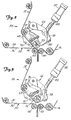
- Figure 2 is a side view of an attaching mechanism on the tape handle forming apparatus of the present invention, illustrating the mechanism in a state for mounting the deadening material onto the handle tape, with some parts broken away or shown in section.
- Figure 3 is a side view of the attaching mechanism, illustrating the mechanism in a state for severing the deadening material, with some parts broken away or shown in section.
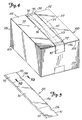
- Figure 4 is a perspective view of a tape handle of the present invention attached to a box.
- Figure 5 is a perspective view of the tape handle of the present invention separate from a box and laid flat.
- Figure 6 is an exploded view showing the box sealing tape, the deadening material and the handle tape components of the tape handle of the present invention.
- Figure 7 is a top view of a tape folding mechanism of the present invention.
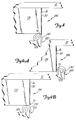
- Figures 8, 9A and 9B are top views showing the tape engaging roller of the folding mechanism in its two operative positions.
- Figure 10 is a sectional view taken along line 10--10 in Figure 5.
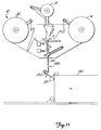
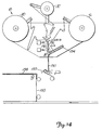
- Figures 11-14 are schematic views of the inventive apparatus showing its sequence of operation in forming and applying a tape handle to a box.
- FIG. 1 An apparatus generally indicated at 10 of the present invention is illustrated in Figure 1.
- the apparatus 10 incorporates two tape-applying devices 12 and 14.
- the Deering, Jr. U.S. Patent 4,238,269 describes a tape applying device having a linearly retractable application member that is suitable for use with the present invention.
- a commercially available example of an apparatus that can use the present invention is a taping head sold under the trademark ACCUGLIDE by Minnesota Mining and Manufacturing Company of St. Paul, Minnesota.
- the present invention may also be used with tape applying devices having pivotally mounted application members.
- the devices 12 and 14 are positioned to apply lengths of pressure-sensitive adhesive coated tape from supply lengths of tape 16 and 18, respectively, held by spools 21 and 23, one after another around the exterior of an object such as a rectangular box 100 that travels along a predetermined path through the apparatus 10.
- the box 100 includes a first upright side 101, a second upright side 103 which is adjacent and generally perpendicular to said first side 101, and a third upright side 105 adjacent to said second side 103 and which is spaced from and generally parallel to said first side 101.
- Each length of box sealing tape 16 has a back side 17 and an adhesive side 19.
- a path from the spool 21 to the box 100 is defined by a box sealing tape path which first includes a box sealing tape dancer arm 25.
- the box sealing tape 16 winds off the spool 21 over the box sealing tape dancer arm 25.
- the box sealing tape dancer arm 25 is spring biased and keeps the slack out of the box sealing tape 16 as the box sealing tape 16 works its way toward the box 100.
- the box sealing tape path is further defined by the box sealing tape 16 winding off the spool 21 and over the box sealing tape dancer arm 25 where it loops around a plurality of initial rollers 27 before coming to a box sealing tape prestrip roller 29.
- the initial rollers 27 further assist in keeping the slack out of the box sealing tape 16 before the box sealing tape 16 reaches the box sealing tape prestrip roller 29.
- the box sealing tape prestrip roller 29 is a driven roller and is designed to only strip the box sealing tape 16 from the spool 21 when tension is present in the box sealing tape 16. Tension is provided by the box 100 moving through the apparatus 10 and pulling on the box sealing tape 16.
- the box sealing tape path continues as the box sealing tape 16 passes over a plurality of secondary rollers 31, 33.
- the secondary rollers 31, 33 assist in maintaining the box sealing tape 16 taut.
- the box sealing tape 16 continues downwardly toward the box 100 along the box sealing tape path until the box sealing tape 16 reaches the box 100.
- the box sealing tape 16 passes over a phasing roller 15.
- the phasing roller 15 keeps the box sealing tape 16 taut and the phasing roller 15 is adjustable depending on the size of box 100 being sealed.
- a plurality of additional rollers 13 keep the box sealing tape 16 in line as the box sealing tape 16 makes its way to the box 100.
- the apparatus 10 includes a base portion 20 supporting the tape-applying device 14.
- a conveying mechanism is adapted to move a box 100 placed along the path and past the devices 12 and 14.
- the device 12 is supported by a vertically movable frame portion (not shown) that is adapted to move vertically to bring the uppermost device 12 into contact with the top surface portions of the box 100 while the box 100 is being moved through a apparatus 10.
- the devices 12 and 14 of the apparatus 10 function in the same manner and have essentially the same parts.
- the device 12 is mounted to apply tape to a top side 99 of the box 100, the top side having a length.
- the device 14 is mounted to apply tape to a bottom surface of the box 100.
- the device 14 includes a tape cutter 152 ( Figure 1) which severs the box sealing tape after a suitable length has been applied to the bottom of the box 100.
- the device 12 has a tape cutter 150 which is shown schematically in Figures 11-14. The cutter 150 severes the box sealing tape 16 so that the box 100 can continue through the apparatus 10 and the box sealing tape 16 can begin taping a new box.
- the apparatus 10 includes a supply of handle tape 30 and a supply of deadening material 32 is provided.
- Each length of handle tape 30 has an adhesive side 34 and a back side 36.
- the handle tape 30 and the deadening material 32 are provided in coils which are rotatably mounted on spools 38, 40, respectively, which, in turn, are mounted on the frame 22.
- a path from the spool 38 to the box 100 is defined by a handle tape path which first includes a handle tape dancer arm 42.
- the handle tape 30 winds off the spool 38 over the handle tape dancer arm 42.
- the handle tape dancer arm 42 is spring biased and keeps the slack out of the handle tape 30 as the handle tape 30 works its way toward the box 100.
- the handle tape path is further defined by the handle tape 30 winding off the spool 38 and over the handle tape dancer arm 42 where it loops around an initial roller 44 before coming to a handle tape feed roller 46.
- the initial roller 44 further assists in keeping the slack out of the handle tape 30 before the handle tape 30 reaches the handle tape feed roller 46.
- the handle tape feed roller 46 is a driven roller and is designed to only strip the handle tape 30 from the spool 38 when tension is present in the handle tape 30. Tension is provided by the box 100 moving through the apparatus 10 and pulling on the handle tape 30.
- the handle tape path continues as the handle tape 30 passes over a plurality of secondary rollers 48, 50, 52 before it reaches an attachment mechanism 54.
- the secondary rollers 48, 50, 52 assist in maintaining the roller tape 30 taut.
- the attachment mechanism 54 attaches the deadening material 32 to the handle tape 30 as detailed below.
- a path from the spool 40 to the box 100 is defined by a deadening material path which first includes a deadening material dancer arm 56.
- the deadening material 32 winds off the spool 40 over the deadening material dancer arm 56.
- the deadening material dancer arm 56 is spring biased and keeps the slack out of the deadening material 32 as the deadening material 32 works its way toward the box 100.
- the deadening material path continues by the deadening material 32 being routed over a plurality of tension rollers 58, 60, 62 until it reaches the attachment mechanism 54.
- the tension rollers 58, 60, 62 assist in maintaining the deadening material 32 taut.
- the attachment mechanism 54 attaches the deadening material 32 to the handle tape 30 as detailed below.
- the attachment mechanism 54 aligns the deadening material 32 with the adhesive side 34 of the handle tape 30. As best illustrated in Figures 2 and 3, the attachment mechanism 54 is movable between an initial position 64 ( Figure 2) and a secondary position 66 ( Figure 3).
- the attachment mechanism 54 includes a main body 68, a retention mechanism 70 and a main body gear assembly 72 fixedly mounted to the main body 68.
- the main body 68 is pivotally mounted on the frame 22 through a pivot point (not shown).
- the retention mechanism 70 is mounted on the main body 68 and urges the deadening material 32 against an application roller 73 of the attachment mechanism 54 through the use of a pinching mechanism 74.
- the main body gear assembly 72 is designed to matingly join a corresponding compatible gear assembly 76 as discussed below.
- the attachment mechanism 54 further comprises a blade arm 78 having a blade 80 mounted on one end thereof and a corresponding gear assembly 76 fixedly mounted at the other end thereof.
- the blade arm 78 is attached to an attachment mechanism activator 82.
- the blade arm 78 is movable between a first position as illustrated in Figure 2 and a second position as illustrated in Figure 3.
- the blade arm 78 is operably coupled with the main body 68 through the corresponding gear assembly 76 and the main body gear assembly 72 such that when the blade arm 78 is in its first position, the blade 80 is spaced away from the deadening material 32 and the attachment mechanism 54 is in its initial position 64 ( Figure 2) which urges (via application roller 73) the deadening material 32 against the adhesive side 34 of the handle tape 30.
- the attachment mechanism is moved to its second position 66 ( Figure 3)
- the blade 80 is moved into its second position and severs the deadening material 32 into a length, thereby pulling the unsevered or remaining deadening material 32 away from the handle tape 30.
- the movement of the attachment mechanism 54 between its initial position 64 and its secondary position 66 is activated through the attachment mechanism activator 82.
- the attachment mechanism activator 82 is controlled by a plurality of switches 84, 86, namely a first switch 84 and a second switch 86.
- the first switch 84 is activated mechanically by the box 100 entering the apparatus 10 and forcing an application mechanism 89 into a taping position which activates the first switch 84.
- an extensible arm 85 of the activator 82 is retracted and moves the attachment mechanism 54 to its initial position 64. This process commences the application of the deadening material 32 to the adhesive side 34 of the handle tape 30.
- the blade arm 78 in response to the attachment mechanism 54 moving to its initial position 64, moves away from the deadening material 32 such that the blade 80 does not severe the deadening material 32.
- the second switch 86 is mechanically activated by the box 100.
- the arm 85 of the activator 82 is extended to move the attachment mechanism 54 into its secondary position 66 and moves the deadening material 32 away from the handle tape 30.
- the remaining deadening material 32 is maintained within the attachment mechanism 54 by the pinching mechanism 74 such that a leading edge of the deadening material 32 is maintained in a ready fashion for the next box to activate the first switch 84.
- the blade arm 78 moves towards the deadening material 32 and thereby allows the blade 80 to sever a discrete strip of the deadening material 32 from the supply thereof.
- the strip of deadening material 32 is severed into a length shorter than the length of the handle tape 30. As illustrated in Figures 4, 5 and 6, the combined deadening material 32 and handle tape 30 forms a handle assembly 88 having first and second adhesive sections 90 and 92 and an intermediate adhesive masked section 94. The first and second adhesive sections 90 and 92 are adhered to the box sealing tape 16 on the box 100 as described further below.
- the first switch 84 and the second switch 86 permits the cutting of a length of deadening material 32 which may be approximately two inches less than the length of the top side 99 of the box 100.
- the first switch 84 and the second switch 86 are triggered by the box 100 moving through the apparatus 100 and control the length of the deadening material 32 depending on the length of the box 100. Therefore, as illustrated in Figure 4, the deadening material 32 will be attached to the adhesive side 34 of the handle tape 30 so that upon application to the box 100, the end edges of the deadening material are preferably spaced from each edge 102, 104 of the top side 99 of the box 100 (e.g., a spacing of 2.54 cm (one inch)).
- the first and second adhesive sections 90 and 92 of the handle tape 30 are applied to the back side 17 of the box sealing tape 16 such that the handle tape 30 lies generally flush, but not taut, to the box sealing tape 16.
- the handle tape 30 is not taut to assist in a person being able to put his hand between the handle tape 30 and the box sealing tape 12 in order to assist in carrying the box.
- the nip rollers 110 are spaced apart such that when the handle tape 32 and the box sealing tape 16 pass through a nip defined by the nip rollers 110, the first and second adhesive sections 90 and 92 of the handle tape 30 are urged against the back side 17 of the box sealing tape 16 to adhere thereto.
- Each strip of combined box sealing tape 16, handle tape 30 and deadening material 32, applied to each box 100 will have approximately seven and one-half inches without deadening material 32 attached (a section of 9.5 cm (three and three-quarters inches) at each end of the combination). It is also within the scope of the present invention to have the deadening material 32 have a length equal to the length of the top side 99 of the box 100, thereby extending from one edge 102 to the other edge 104. By having the deadening material equal in length to the top side 99, the first and second adhesive sections 90 and 92 are adhered only to the box sealing tape 16 which is adhered to opposed, substantially parallel sides of the box.
- the handle tape 30 will not adhere to the box sealing tape 16 where the deadening material 32 is present simply because the deadening material 32 has covered the adhesive over that portion of the handle tape 30. This provides for the handle tape 30 to be free from the box sealing tape 16 thereby forming a handle 112 when the box sealing tape 16 is adhered to the box 100 as illustrated in Figure 4.
- the box sealing tape 16 preferably has a longitudinal side edge 114, as shown in phantom in Figure 5, wherein the handle assembly 88, as applied to the box sealing tape 16, is slightly wider than the box sealing tape 16. It should be noted that the handle assembly 88 can also be the same width or narrower than the box sealing tape 16 so long as a portion of the handle assembly 88 laterally overhangs the box sealing tape 16. The handle assembly 88 can also laterally overhang the box sealing tape 16 on only one lateral side or on both lateral sides of the box sealing tape 16.
- the first adhesive section 90 has a first edge portion 91 which overlies the side edge 114 of the box sealing tape 16 and the second adhesive section 92 has a second edge portion 93 which overlies the side edge 114 of the box sealing tape 16.
- the apparatus 10 further includes a first folding mechanism 120 and a second folding mechanism 122.
- the apparatus 10 of the present invention preferably includes two folding mechanisms 120, 122, reference will be made only to the first folding mechanism 120. It should be understood that the second folding mechanism 122 operates in the same manner. It should also be understood that the scope of the present invention includes four folding mechanisms such that the folds can be made on both sides of the tape simultaneously. Operation of a folding mechanism is discussed in detail below.
- the folding mechanism 120 is activated through an actuator or air cylinder 134, as illustrated in Figure 7, by the activation of the first switch 84 as discussed above.
- the air cylinder 134 includes an extensible arm 135 pivotally attached to the folding arm 128 through a pivot pin 137.
- the folding mechanism 120 is in its second operable position 126 (See Figure 9A).
- the arm 135 When the first switch 84 is activated, the arm 135 is retracted into the air cylinder 134 to move the folding mechanism 120 into its first retracted position 124, as illustrated in Figure 9B, away from the first and second edge portions 91 and 93 (in Figures 8, 9A and 9B, only edge portion 91 is illustrated).
- the folding mechanism 120 is retracted completely to the first retracted position 124 before the handle tape 30 and the box sealing tape 16 are advanced.
- Figure 9B illustrates the folding mechanism 120 in its first retracted position 124 after the folding mechanism 120 has retracted and before the handle tape 32 and the box sealing tape 16 begin to travel down their respective paths towards the box 100.
- the second switch 86 is contacted by the trailing edge of the box 100 as the box 100 is travelling through the apparatus 10. This contact causes the deadening material 32 to be severed and thus stop being applied to the handle tape 16. The severing of the deadening tape 32 occurs before the folding mechanism extends to its second operable position 126.
- the handle tape 32 and the box sealing tape 16 cease moving down their respective paths towards the box 100.
- the first switch 84 is once again activated by the application mechanism 89 as the application mechanism 89 returns to a rest position which causes the folding mechanism to extend to its second operable position 126.
- the extensible arm 135 is extended from the air cylinder 134 and causes the folding arm 120 to move toward the combination of the handle tape 30 and the box sealing tape 16.
- the folding arm then moves the roller 130 into contact with the first and second edge portions 91 and 93 and then the spring 133 causes the roller 130 to fold the first and second edge portions 91 and 93 into contact with the adhesive side 19 of the box sealing tape 16, as illustrated in Figure 10, giving a first and a second folded portion 136 and 138, as illustrated in Figures 4 and 5.
- the box sealing tape 16, the handle tape 30 and the deadening material 32 is then attached to the box 100 as illustrated in Figures 11-14.
- the combination creates a handle 112 for carrying the box 100.
- Figures 11-14 illustrate the sequence of applying the handle assembly to a box.
- Figure 11 illustrates a leading handle assembly 188 as the leading handle assembly 188 begins being applied to a box 100.
- the leading handle assembly 188 is applied to the box 100 by the application mechanism 89 with the leading handle assembly 188 thereunder so that the adhesive side of the leading handle assembly 188 is in contact with the box 100.
- a second handle assembly 190 is already beginning its way down the path towards the box 100.
- the beginning of the deadening material 132 for the leading handle assembly 188 is denoted at A while the end of the deadening material 132 for the leading handle assembly 188 is denoted at B.
- the end of the leading handle assembly 188 and the beginning of the second handle assembly 190 is denoted at X.
- the leading handle assembly 188 will be severed from the second handle assembly 190 at point X by tape cutter 150.
- the severance of tape after it has been applied to a box is well known in the art. At X, the severance creates the beginning of the second handle assembly 190.
- the beginning of deadening material 134 for the second handle assembly 190 is denoted at C.
- the box 100 has advanced and is approximately one-third through the apparatus 10.
- the leading handle assembly 188 is pulled along the path towards the box 100.
- the leading handle assembly 188 has already been applied to the box 100 on a perpendicular side and a portion of the top side along the seam.
- the second handle assembly 190 has also continued along the same path with the severing point denoted at X.
- the beginning of the deadening material 134 for the second handle assembly 190 is denoted at C.
- the ending point for the deadening material 134 for the second handle assembly 190 has not yet been reached as viewed in Figure 12.
- the preferred distance between point B and point C is approximately 19 cm (seven and one-half inches), however, other distances may be used depending on the size and shape of the box being used.
- Figure 14 illustrates the placement of the leading handle assembly 188 as the box 100 leaves the apparatus 10.
- Deadening material 136 for a third handle assembly 192 is beginning to be applied to the third handle assembly 192 at point E.
- Point X' denotes the severing point between the second handle assembly 190 and the third handle assembly 192.
- the leading handle assembly 188 has been severed from the second handle assembly 190 such that the leading handle assembly 188 is now completely separate from the second handle assembly 190 and the leading handle assembly 188 is attached to the box.
- the end of the deadening material 134 of the second handle assembly 190 is denoted at D while the beginning of the deadening material 136 of the third handle assembly 190 is denoted at E.
- the second handle assembly 190 and the third handle assembly 192 are severed at point X' and the distance between D and E is approximately 19 cm (seven and one-half inches) depending on the size and the shape of the box.
- the folding mechanisms 120 and 122 are activated to simultaneously fold over the second edge of the second handle assembly 190 and the first edge of the third handle assembly 192.
- the folding mechanisms 120 and 122 are activated by the switch 84, as discussed above.
- the first and second edge portions 91 and 93 are folded under the edge of the box sealing tape 16 prior to the box sealing tape 16 being applied to the box 100.
- the box sealing tape 16 is adhered to adjacent, generally perpendicular sides of the box 100 such that portions of each of the first and second adhesive sections 90 and 92 of the handle assembly 88 overlie adjacent, generally perpendicular sides of the box 100 and the box sealing tape 16 is aligned longitudinally over a seam 113 between two opposed flaps 115, 117 of the box 100.
- each folded edge portion 136, 138 overlies adjacent, generally perpendicular sides of the box 100 and that each folded edge portion 136, 138 is placed over the edges 104, 102, respectively.
- the handle assembly 88 lays flush against the box 100 as illustrated in Figure 4. This allows multiple boxes to be stacked without the handles 112 protruding from between the boxes.
- the deadening material 32 is selected from the group consisting of film, single coated tape and paper.
- the length of the handle on any given box can be varied depending on the size of the box and the contents of the box.
- the taping apparatus can be adjusted to tape any given length of box.
- the length of deadening material on any given handle may be adjusted to provide for a larger or a smaller handle.
Landscapes
- Engineering & Computer Science (AREA)
- Mechanical Engineering (AREA)
- Package Closures (AREA)
- Making Paper Articles (AREA)
- Auxiliary Devices For And Details Of Packaging Control (AREA)
- Package Frames And Binding Bands (AREA)
- Adhesive Tape Dispensing Devices (AREA)
Claims (27)
- Verfahren zur Herstellung von Tragegriffen (112) für Schachteln (100), wobei das Verfahren zur Herstellung eines jeden Tragegriffes die folgenden Schritte umfaßt:
Bereitstellen eines Streifens Schachtelversiegelungsband (16) mit einer Klebeseite (19) und einer Rückseite (17);
Bereitstellen eines Streifens Tragegriffband (30) mit einer Klebeseite (34) und einer Rückseite (36);
Bereitstellen eines Streifens Abdeckmaterial (32), wobei der Streifen Abdeckmaterial kürzer ist als das Tragegriffband;
Positionieren des Streifens Abdeckmaterial auf der Klebeseite des Tragegriffbandes, wodurch eine Tragegriffanordnung (88) mit einem ersten und einem zweiten Klebeabschnitt (90, 92) und einem mittleren abgedeckten Abschnitt (94) gebildet wird; und
Aufkleben des ersten und des zweiten Klebeabschnitts der Tragegriffanordnung auf die Rückseite des Schachtelversiegelungsbandes. - Verfahren nach Anspruch 1, bei dem das Schachtelversiegelungsband (16) eine Längsseitenkante (114) besitzt, des weiteren umfassend die folgenden Schritte:
die Tragegriffanordnung (88) seitlich an dem Schachtelversiegelungsband überstehen lassen, so daß der erste Klebeabschnitt (90) einen ersten Kantenabschnitt (91) besitzt, der über der Seitenkante des Schachtelversiegelungsbandes liegt, und der zweite Klebeabschnitt (92) einen zweiten Kantenabschnitt (93) besitzt, der über der Seitenkante des Schachtelversiegelungsbandes liegt; und
Falten von mindestens einem Abschnitt des ersten und des zweiten Kantenabschnitts (91, 93) unter die Seitenkante des Schachtelversiegelungsbandes. - Verfahren nach Anspruch 2 und des weiteren umfassend den folgenden Schritt:
den unter die Seitenkante des Schachtelversiegelungsbandes (16) gefalteten ersten und zweiten Kantenabschnitt (91, 93) gegen die Klebeseite (17) des Schachtelversiegelungsbandes drücken. - Verfahren nach Anspruch 1 und des weiteren umfassend den folgenden Schritt:
Aufkleben des Schachtelversiegelungsbandes (16) auf eine Schachtel (100). - Verfahren nach Anspruch 4 und des weiteren umfassend den folgenden Schritt:
Ausrichten des Schachtelversiegelungsbandes (16) und der Tragegriffanordnung (88), so daß Endabschnitte des Schachtelversiegelungsbandes auf einander gegenüberliegende, im wesentlichen parallele Seiten der Schachtel geklebt werden. - Verfahren nach Anspruch 5 und des weiteren umfassend den folgenden Schritt:
Ausrichten des Schachtelversiegelungsbandes (16) und der Tragegriffanordnung (88), so daß der erste und der zweite Klebeabschnitt (90, 92) der Tragegriffanordnung jeweils über mindestens einer Kante längs benachbarter Seiten der Schachtel (100) liegt. - Verfahren nach Anspruch 3 und des weiteren umfassend den folgenden Schritt:
Ausrichten jedes gefalteten Kantenabschnitts, so daß er über einer Kante der Schachtel (100) längs deren benachbarter Seiten liegt. - Verfahren nach Anspruch 4 und des weiteren umfassend den folgenden Schritt:
Ausrichten des Schachtelversiegelungsbandes (16) in Längsrichtung über einer Naht (113) zwischen zwei einander gegenüberliegenden Klappen (115, 117) der Schachtel (100). - Kombination einer Aufbringvorrichtung (12, 14) für ein Schachtelversiegelungsband, die eine kontinuierliche Bahn Schachtelversiegelungsband (16) mit einer zu versiegelnden Naht (113) längs einer Seite einer Schachtel ausrichtet, das Schachtelversiegelungsband in Längsrichtung über der Naht aufbringt und das Schachtelversiegelungsband in einer gewünschten Länge abschneidet, so daß seine Endabschnitte auf die einander gegenüberliegenden, im wesentlichen parallelen Seiten der Schachtel aufgeklebt werden, und einer Vorrichtung zum Aufbringen einer Tragegriffanordnung auf das Stück Schachtelversiegelungsband, umfassend:
eine Einrichtung zur Bereitstellung eines Streifens Tragegriffband (16) mit einer Klebeseite (19) und einer Rückseite (17);
eine Einrichtung zur Bereitstellung eines Streifens Abdeckmaterial (32), wobei das Abdeckmaterial kürzer ist als das Tragegriffband;
eine Einrichtung zur Positionierung des Abdeckstreifens auf der Klebeseite des Tragegriffbandes, wodurch eine Tragegriffanordnung (88) mit einem ersten und einem zweiten Klebeabschnitt und einem dazwischenliegenden abgedeckten Abschnitt gebildet wird; und
eine Einrichtung zum Aufkleben des ersten und des zweiten Klebeabschnitts der Tragegriffanordnung auf die Rückseite des Schachtelversiegelungsbandes. - Kombination nach Anspruch 9, bei der der Streifen Abdeckmaterial aus einer kontinuierlichen Bahn eines solchen Materials besteht, und bei der die Einrichtung zum Positionieren des Streifens Abdeckmaterial auf der Klebeseite des Tragegriffbandes einen Aufbringmechanismus (54) umfaßt, der zwischen einer Ausgangsposition und einer zweiten Position bewegbar ist, eine Klinge (80), die zwischen einer ersten Position und einer zweiten Position bewegbar ist, und eine Einrichtung zum Bewegen der Klinge, wobei die Klinge funktional mit dem Aufbringmechanismus gekoppelt ist, so daß dann, wenn sich die Klinge in ihrer ersten Position befindet, die Klinge von der Bahn Abdeckmaterial beabstandet ist und der Aufbringmechanismus sich in seiner Ausgangsposition befindet, in der der Streifen Abdeckmaterial gegen die Klebeseite des Tragegriffbandes gedrückt wird, so daß dann, wenn sich die Klinge in ihrer zweiten Position befindet, die Klinge den Streifen Abdeckmaterial von der Bahn trennt, und der Aufbringmechanismus sich in seiner zweiten Position befindet, in der die Bahn Abdeckmaterial von dem Tragegriffband weggedrückt wird.
- Kombination nach Anspruch 9, bei der das Schachtelversiegelungsband (16) eine Längsseitenkante (114) besitzt, und die auf das Schachtelversiegelungsband aufgebrachte Tragegriffanordnung seitlich an dem Schachtelversiegelungsband übersteht, so daß der erste Klebeabschnitt (90) einen ersten Kantenabschnitt (91) besitzt, der über der Seitenkante des Schachtelversiegelungsbandes liegt, und der zweite Klebeabschnitt (92) einen zweiten Kantenabschnitt (93) besitzt, der über der Seitenkante des Schachtelversiegelungsbandes liegt, und bei der die Einrichtung zum Aufkleben Mittel (120, 122) umfaßt, die in einen der Kantenabschnitte eingreifen, und mindestens einen Abschnitt davon umbiegt und mit der Klebeseite des Schachtelversiegelungsbandes in Eingriff bringt.
- Komnbination nach Anspruch 9 zum Versiegeln von Schachteln, die in einer durchgehenden Reihe an der Vorrichtung vorbeibewegt werden, und zum gleichzeitigen Aufbringen eines Tragegriffes auf jede Schachtel (100), wobei die Vorrichtung folgendes umfaßt:
einen Rahmen (22);
eine Quelle für Schachtelversiegelungsband (16) mit einer Klebeseite (19) und einer Rückseite (17), die auf dem Rahmen gelagert ist;
eine Anordnung (12, 14) zum Aufbringen des Schachtelversiegelungsbandes, die funktional auf dem Rahmen gelagert ist, um eine Vorderkante des Schachtelversiegelungsbandes mit einer Schachtel auszurichten, und um einen ersten Endabschnitt des Schachtelversiegelungsbandes gegen eine erste Seite (101) der Schachtel, einen mittleren Abschnitt des Schachtelversiegelungsbandes gegen eine zweite Seite (99) der Schachtel, und einen zweiten Endabschnitt des Schachtelversiegelungsbandes, der an einer Hinterkante endet, gegen eine dritte Seite (105) der Schachtel zu drücken, wobei die dritte Seite im allgemeinen parallel und im Abstand zu der ersten Seite verläuft;
eine Schneidvorrichtung für das Schachtelversiegelungsband, die funktional auf dem Rahmen gelagert ist, um ein Stück Schachtelversiegelungsband für jede Schachtel von der Bandquelle längs der Hinterkante des Stückes abzuschneiden;
eine Quelle für Tragegriffband (30) mit einer Klebeseite (34) und einer Rückseite (36), die auf dem Rahmen gelagert ist;
eine Quelle für Abdeckmaterial (32), die auf dem Rahmen gelagert ist;
eine Schneidvorrichtung für das Abdeckmaterial, die funktional auf dem Rahmen gelagert ist, um ein erstes Stück Abdeckmaterial von seiner Quelle abzuschneiden;
eine auf dem Rahmen gelagerte Anordnung (54) zum Ausbilden des Tragegriffes, die, bevor das Schachtelversiegelungsband auf die Schachtel aufgebracht und von seiner Quelle abgeschnitten wird, einen Tragegriff ausbildet, indem die Klebeseite des Tragegriffbandes gegen die Rückseite des Schachtelversiegelungsbandes gedrückt wird, wobei das Abdeckmaterial dazwischenliegt, so daß jeder so ausgebildete Tragegriff einen ersten und einen zweiten Endabschnitt besitzt, wobei das Tragegriffband auf das Schachtelversiegelungsband aufgeklebt wird, und einen mittleren Abschnitt, wobei das Abdeckmaterial verhindert, daß Tragegriffband und das Schachtelversiegelungsband aneinanderkleben; und
bei der die Vorrichtung zum Aufbringen des Schachtelversiegelungsbandes das Tragegriffband und das Abdeckmaterial zusammen mit dem Schachtelversiegelungsband aufbringt, und
bei der die Schneidvorrichtung für das Schachtelversiegelungsband das auf das Schachtelversiegelungsband aufgeklebte Tragegriffband von seiner Quelle abschneidet, und zwar auf eine der Länge des Schachtelversiegelungsbandes für jede Schachtel entsprechende Länge. - Kombination nach Anspruch 9, bei der die Vorrichtung folgendes umfaßt:
einen Rahmen (22);
eine Quelle für Tragegriffband (30) mit einer Klebeseite (34) und einer Rückseite (36), die auf dem Rahmen gelagert ist;
eine Quelle für Abdeckmaterial (32), die auf dem Rahmen gelagert ist,
eine erste Schneidvorrichtung, die funktional auf dem Rahmen gelagert ist, um ein erstes Stück Abdeckmaterial von der Abdeckmaterialquelle abzuschneiden;
eine erste Anordnung (54), die funktional auf dem Rahmen gelagert ist, um das erste Stück Abdeckmaterial gegen die Klebeseite eines zweiten, längeren Stücks Tragegriffband (30) zu drücken, so daß eine Tragegriffanordnung (88, 188) aus dem zweiten Stück gebildet wird mit ersten und zweiten Klebeabschnitten (90, 92) und einem mittleren abgedeckten Klebeabschnitt (94), wobei die Tragegriffanordnung eine freie Vorderkante und eine mit der Quelle für das Tragegriffband verbundene Hinterkante besitzt;
eine zweite Anordnung (12, 14), die funktional auf dem Rahmen gelagert ist, um die Vorderkante der Tragegriffanordnung mit einer Schachtel auszurichten und den ersten Klebeabschnitt (90) gegen eine erste Seite der Schachtel zu drücken, wobei der abgedeckte Abschnitt im allgemeinen bündig entlang einer zweiten Seite (99) der Schachtel verläuft, und den zweiten Klebeabschnitt gegen eine dritte Seite der Schachtel, die im allgemeinen parallel und im Abstand zu der ersten Seite verläuft; und
eine zweite Schneidvorrichtung (150), die funktional auf dem Rahmen gelagert ist, um die Tragegriffanordnung von der Quelle für das Tragegriffband längs der Hinterkante zu trennen. - Kombination nach Anspruch 13 und des weiteren umfassend:
eine Quelle für Schachtelversiegelungsband (16) mit einer Klebeseite (19) und einer Rückseite (17), die auf dem Rahmen (22) gelagert ist;
wobei die erste Anordnung (54) des weiteren den ersten und den zweiten Klebeabschnitt der Tragegriffanordnung gegen die Rückseite eines Stückes Schachtelversiegelungsband drückt, so daß die Tragegriffanordnung auf das Stück Schachtelversiegelungsband geklebt wird und im allgemeinen bündig daran liegt;
wobei die zweite Anordnung (12, 14) die Tragegriffanordnung auf die Schachtel aufbringt, so daß das Schachtelversiegelungsband darunterliegt, und die Klebeseite des Schachtelversiegelungsbandes mit der Schachtel in Kontakt steht; und
wobei die zweite Schneidvorrichtung des weiteren das Stück Schachtelversiegelungsband von der Quelle für dieses Band abschneidet. - Kombination nach Anspruch 13, bei der die erste Schneidvorrichtung einen Aufbringmechanismus umfaßt, der zwischen einer Ausgangsposition und einer zweiten Position bewegbar ist, eine Klinge (80), die zwischen einer ersten Position und einer zweiten Position bewegbar ist, und eine Einrichtung zum Bewegen der Klinge, wobei die Klinge funktional mit dem Aufbringmechanismus verbunden ist, so daß dann, wenn sich die Klinge in der ersten Position befindet, die Klinge von der Quelle für Abdeckmaterial (32) beabstandet ist, und der Aufbringmechanismus sich in seiner Ausgangsposition befindet, in der ein festgelegtes Stück Abdeckmaterial gegen die Klebeseite des Tragegriffbandes gedrückt wird, so daß dann, wenn sich die Klinge in ihrer zweiten Position befindet, die Klinge das Abdeckmaterial von seiner Quelle abschneidet und der Aufbringmechanismus sich in seiner zweiten Position befindet, in der die Quelle für das Abdeckmaterial von dem Tragegriffband weggedrückt wird.
- Kombination nach Anspruch 14, bei der das Schachtelversiegelungsband (16) eine Längsseitenkante (114) besitzt, und bei der die auf das Schachtelversiegelungsband aufgebrachte Tragegriffanordnung (88, 188) seitlich über das Schachtelversiegelungsband hinaussteht, so daß der erste Klebeabschnitt einen ersten Kantenabschnitt (91) besitzt, der über der Seitenkante des Schachtelversiegelungsbandes liegt, und der zweite Klebeabschnitt einen zweiten Kantenabschnitt (93) besitzt, der über der Seitenkante des Schachtelversiegelungsbandes liegt, und wobei die erste Anordnung eine Einrichtung (120, 122) umfaßt, die in einen der Kantenabschnitte eingreift und mindestens einen Teil davon umbiegt und mit der Klebeseite des Schachtelversiegelungsbandes in Eingriff bringt.
- Kombination nach Anspruch 14, bei der jede auf das Stück Schachtelversiegelungsband aufgebrachte Tragegriffanordnung einen einzelnen Tragegriff zum Aufbringen auf eine Schachtel bildet, und bei der ein erster vorderer Tragegriff (188) auf eine erste Schachtel aufgebracht wird und ein zweiter hinterer Tragegriff (190) auf eine nächste. Schachtel aufgebracht wird und so weiter, wobei die zweite Schneidvorrichtung (150) die Länge jedes Tragegriffs festlegt und benachbarte Tragegriff längs einer die Trennung zwischen dem zweiten Klebeabschnitt des vorderen Tragegriffs und dem ersten Klebeabschnitt des hinteren Tragegriffs definierenden Linie durchschneidet, wobei der hintere Tragegriff immer noch mit der Quelle für Tragegriffband und für Schachtelversiegelungsband verbunden ist.
- Kombination nach Anspruch 17, bei der das Schachtelversiegelungsband (16) eine Längsseitenkante (114) besitzt, und jede auf das jeweilige Stück Schachtelversiegelungsband aufgebrachte Tragegriffanordnung (88) seitlich über das Schachtelversiegelungsband hinaussteht, so daß der erste Klebeabschnitt (90) einen ersten Kantenabschnitt (91) besitzt, der über der Seitenkante des Schachtelversiegelungsbandes liegt, und der zweite Klebeabschnitt (92) einen zweiten Kantenabschnitt (93) besitzt, der über der Seitenkante des Schachtelversiegelungsbandes liegt, und bei der die erste Anordnung eine Einrichtung umfaßt, die mit dem zweiten Kantenabschnitt des vorderen Tragegriffs und mit dem ersten Kantenabschnitt des hinteren Tragegriffs in Eingriff kommt, um einzelne Segmente dieser Abschnitte umzubiegen und mit der Klebeseite des Schachtelversiegelungsbandes für jeden Tragegriff in Eingriff zu bringen.
- Kombination nach Anspruch 18, bei der die zweite Anordnung jeden Tragegriff auf seine zugehörige Schachtel aufbringt, so daß die umgebogenen Segmente des ersten und des zweiten Klebeabschnitts der Tragegriffanordnung jeweils über einer Seitenkante der Schachtel ausgerichtet sind.
- Schachtel mit einem Tragegriff (112) zum Tragen einer Schachtel (100), bei der auf die Schachtel mindestens ein Streifen Schachtelversiegelungsband (16) aufgeklebt ist, wobei der Tragegriff folgendes umfaßt:
einen Streifen Tragegriffband (16) mit einer Klebeseite (19) und einer Rückseite (12); und
einen Streifen Abdeckmaterial (32), der kürzer ist als das Tragegriffband und auf die Klebeseite des Tragegriffbandes aufgeklebt wird, so daß eine Tragegriffananordnung mit einem ersten und einem zweiten Klebeabschnitt (90, 97) und einem mittleren abgedeckten Abschnitt (94) gebildet wird, dadurch gekennzeichnet, daß der erste und der zweite Klebeabschnitt der Tragegriffanordnung auf das Schachtelversiegelungsband auf der Schachtel geklebt werden. - Schachtel nach Anspruch 20, bei der das Schachtelversiegelungsband (16) eine Längsseitenkante (114) besitzt, und bei der die auf das Schachtelversiegelungsband aufgebrachte Tragegriffanordnung (88) seitlich über das Schachtelversiegelungsband hinaussteht, so daß der erste Klebeabschnitt (90) einen ersten Kantenabschnitt (91) besitzt, der über der Seitenkante des Schachtelversiegelungsbandes liegt, und der zweite Klebeabschnitt (92) einen zweiten Kantenabschnitt (93) besitzt, der über der Seitenkante des Schachtelversiegelungsbandes liegt.
- Schachtel nach Anspruch 20, bei der mindestens ein Teil des ersten und des zweiten Kantenabschnitts unter die Kante des Schachtelversiegelungsbandes gefaltet wird, bevor das Schachtelversiegelungsband auf die Schachtel aufgebracht wird.
- Schachtel nach Anspruch 20, bei der Endabschnitte des Schachtelversiegelungsbandes auf gegenüberliegende, im wesentlichen parallele Seiten (101, 105) der Schachtel geklebt werden.
- Schachtel nach Anspruch 23, bei der das Schachtelversiegelungsband auf die Schachtel geklebt wird, so daß Teile des ersten und des zweiten Klebeabschnitts (90, 92) der Tragegriffanordnung über einander gegenüberliegenden, voneinander beabstandeten Seitenkanten (102, 104) der Schachtel liegen.
- Schachtel nach Anspruch 21, bei der Endabschnitte des Schachtelversiegelungsbandes auf gegenüberliegende, im wesentlichen parallele Seiten (101, 105) der Schachtel (100) geklebt werden, so daß jeder umgefaltete Kantenabschnitt über einer Seitenkante (102, 104) der Schachtel liegt.
- Schachtel nach Anspruch 20, bei der die Schachtel eine Vielzahl von Seiten besitzt und mindestens zwei Klappen (115, 117), die längs einer Seite angeordnet sind, so daß jede Klappe eine der Kante der anderen Klappe gegenüberliegende Kante besitzt, um eine Schachtelnaht (113) zu bilden, und bei der das Schachtelversiegelungsband so auf die Schachtel aufgebracht wird, daß ein erster Endabschnitt (90) längs einer ersten Seite der Schachtel aufgebracht wird, ein Mittelabschnitt derselben, der den mittleren abgedeckten Abschnitt (94) der Tragegriffanordnung umfaßt, auf die eine Seite längs aneinanderstoßender Abschnitte der Klappenkanten und damit über die Schachtelnaht aufgebracht wird, und ein zweiter Endabschnitt (97) auf eine zweite Seite der Schachtel aufgebracht wird, die der ersten Seite der Schachtel gegenüberliegt und im wesentlichen parallel zu dieser verläuft.
- Schachtel (100) nach Anspruch 20 mit einer ersten Seite (101), einer daran angrenzenden zweiten Seite (99), einer an die zweite Seite angrenzenden und der ersten Seite gegenüberliegenden und im wesentlichen parallel dazu verlaufenden dritten Seite (105), und einem Streifen Schachtelversiegelungsband (16), der darauf aufgeklebt ist, um sich über eine Längsnaht (113) quer über die zweite Seite der Schachtel zu erstrecken, wobei seine Enden die erste und dritte Seite der Schachtel überlappen und auf diese aufgeklebt sind, sowie einen Tragegriff (112) zur Verwendung beim Anheben der Schachtel, der folgendes umfaßt:
einen Streifen Tragegriffband (30) mit einer Klebeseite (34) und einer Rückseite (36); und
einen Streifen Abdeckmaterial (37), der kürzer ist als das Tragegriffband und auf die Klebeseite des Tragegriffbandes aufgeklebt wird, um dadurch eine Tragegriffanordnung (88) mit einem ersten und einem zweiten Klebeabschnitt (90, 92) und einem mittleren abgedeckten Abschnitt (94) zu bilden, wobei der erste Klebeabschnitt auf das Schachtelversiegelungsband auf der ersten Seite der Schachtel geklebt wird, und der zweite Klebeabschnitt auf der dritten Seite der Schachtel auf die Schachtel geklebt wird.
Priority Applications (1)
| Application Number | Priority Date | Filing Date | Title |
|---|---|---|---|
| EP94112777A EP0628483A1 (de) | 1990-09-26 | 1991-09-25 | Behälter mit Griffband |
Applications Claiming Priority (2)
| Application Number | Priority Date | Filing Date | Title |
|---|---|---|---|
| US588683 | 1990-09-26 | ||
| US07/588,683 US5079900A (en) | 1990-09-26 | 1990-09-26 | Method and apparatus for forming a tape handle |
Related Child Applications (1)
| Application Number | Title | Priority Date | Filing Date |
|---|---|---|---|
| EP94112777.1 Division-Into | 1991-09-25 |
Publications (3)
| Publication Number | Publication Date |
|---|---|
| EP0478295A2 EP0478295A2 (de) | 1992-04-01 |
| EP0478295A3 EP0478295A3 (en) | 1993-02-24 |
| EP0478295B1 true EP0478295B1 (de) | 1995-07-19 |
Family
ID=24354866
Family Applications (2)
| Application Number | Title | Priority Date | Filing Date |
|---|---|---|---|
| EP91308727A Expired - Lifetime EP0478295B1 (de) | 1990-09-26 | 1991-09-25 | Verfahren und Vorrichtung zur Herstellung eines Tragegriffes und eine Schachtel mit einem solchen Tragegriff |
| EP94112777A Withdrawn EP0628483A1 (de) | 1990-09-26 | 1991-09-25 | Behälter mit Griffband |
Family Applications After (1)
| Application Number | Title | Priority Date | Filing Date |
|---|---|---|---|
| EP94112777A Withdrawn EP0628483A1 (de) | 1990-09-26 | 1991-09-25 | Behälter mit Griffband |
Country Status (7)
| Country | Link |
|---|---|
| US (1) | US5079900A (de) |
| EP (2) | EP0478295B1 (de) |
| JP (1) | JPH04234638A (de) |
| BR (1) | BR9104120A (de) |
| CA (1) | CA2052276A1 (de) |
| DE (1) | DE69111351T2 (de) |
| ES (1) | ES2074665T3 (de) |
Families Citing this family (33)
| Publication number | Priority date | Publication date | Assignee | Title |
|---|---|---|---|---|
| US5509251A (en) * | 1984-05-22 | 1996-04-23 | Highland Supply Corporation | Method of wrapping a floral grouping using a wrapper with a handle |
| US6415546B2 (en) | 1988-09-26 | 2002-07-09 | Southpac Trust International, Inc. | Floral grouping with handle incorporated therein |
| US5544469A (en) * | 1988-09-26 | 1996-08-13 | Southpac Trust International, Inc. | Wrapping material having an extension for design indicia for wrapping flower pots and floral arrangements and methods |
| US5784859A (en) * | 1988-09-26 | 1998-07-28 | Southpac Trust International, Inc. | Wrapping material having an extension for design indicia for wrapping flower pots and methods |
| US5720150A (en) * | 1988-09-26 | 1998-02-24 | Southpac Trust International, Inc. | Methods for wrapping floral groupings using a wrapping material having an extension for design indicia |
| US5715649A (en) * | 1988-09-26 | 1998-02-10 | Southpac Trust International, Inc. | Wrapping material having an extension for design indicia forwrapping flower pots and floral arrangements and methods |
| US6295758B1 (en) | 1989-08-09 | 2001-10-02 | Southpac Trust International, Inc. | Floral grouping wrapper with handle incorporated therein |
| JP3080114B2 (ja) | 1992-01-09 | 2000-08-21 | 住友スリーエム株式会社 | タブ付きテープ貼付装置 |
| US6499251B2 (en) | 1998-03-30 | 2002-12-31 | Southpac Trust International, Inc. | Method for providing a decorative cover for a floral grouping |
| US6662497B2 (en) | 2001-07-05 | 2003-12-16 | Southpac Trust International, Inc. | Method for providing a decorative cover for a floral grouping |
| US5467915A (en) * | 1992-10-21 | 1995-11-21 | Roberts Systems, Inc. | Lift-up handle |
| US5318218A (en) * | 1992-10-21 | 1994-06-07 | Roberts Systems, Inc. | Latch for container |
| IT1255976B (it) * | 1992-11-30 | 1995-11-17 | Apparato per applicare maniglie adesive a colli | |
| CH687193A5 (de) * | 1993-08-09 | 1996-10-15 | Rothenberger & Co | Vorrichtung zum Anbringen einer bandfoermigen Handhabe an einem Paket. |
| CA2171860A1 (en) * | 1993-10-07 | 1995-04-13 | Thomas L. Nelson | Pretaped container blanks |
| JPH0724705U (ja) * | 1993-10-14 | 1995-05-12 | 株式会社不二鉄工所 | 包装物のサイドシール装置及びサイドシール包装物 |
| US5511362A (en) * | 1993-11-24 | 1996-04-30 | Nippon Flute Co., Ltd. | Box sealing method and apparatus |
| US5727364A (en) * | 1995-09-14 | 1998-03-17 | Viscofan, Industria Navarra De Envoltras Celulosicas S.A. | Perfected packaging for the wrapping of mainly cylindrical and long shaped bodies, such as artificial tripe |
| FR2749564B1 (fr) * | 1996-06-11 | 1998-07-10 | Sarl Cambo | Appareil pour la fabrication d'elements a base de ruban adhesif, comprenant au moins une zone neutralisee |
| US6088954A (en) * | 1998-03-30 | 2000-07-18 | Southpac Trust International, Inc., | Method for providing a decorative cover for a floral grouping |
| US6055772A (en) | 1999-04-21 | 2000-05-02 | Southpac Trust International, Inc. | Method for providing a decorative cover for a floral grouping |
| US20020029520A1 (en) * | 1998-05-21 | 2002-03-14 | Weder Donald E. | Decorative attachments and methods of use |
| US6047882A (en) * | 1998-08-18 | 2000-04-11 | Sin; Woo H. | Box blanks containing easy-open tabs |
| DE10315116A1 (de) * | 2003-04-03 | 2004-10-14 | Khs Maschinen- Und Anlagenbau Ag | Vorrichtung für das Anbringen von Tragegriffen |
| JP2005229100A (ja) * | 2004-01-13 | 2005-08-25 | Japan Matekkusu Kk | 放熱シート及びヒートシンク |
| FR2893925B1 (fr) * | 2005-11-28 | 2010-05-14 | Sidel Sa | Paquet comprenant un flanc recouvrant partiellement un groupe d'articles. |
| CN103231546B (zh) * | 2013-04-02 | 2015-04-01 | 金红叶纸业集团有限公司 | 手提带安装设备 |
| EP2902352B1 (de) * | 2014-01-31 | 2016-12-21 | Neopost Technologies | Tragbarer griffspender |
| US10051950B2 (en) | 2015-06-29 | 2018-08-21 | H.B. Fuller Company | Discrete handles for containers |
| EP3325388B1 (de) * | 2015-07-20 | 2019-12-11 | Neopost Technologies | Verbesserter tragbarer griffspender |
| US9457943B1 (en) | 2016-04-15 | 2016-10-04 | Handi Foil Corporation | Bundling pans with a tape handle |
| CN110077687B (zh) * | 2019-05-22 | 2024-05-03 | 上海出版印刷高等专科学校 | 纸箱 |
| CN112141444B (zh) * | 2020-11-25 | 2021-02-19 | 万邑通(潍坊)信息科技有限公司 | 一种包裹封箱装置 |
Citations (3)
| Publication number | Priority date | Publication date | Assignee | Title |
|---|---|---|---|---|
| US2967656A (en) * | 1957-09-10 | 1961-01-10 | Pneumatic Scale Corp | Package |
| FR1253685A (fr) * | 1960-04-08 | 1961-02-10 | Welsh Anthracite | Emballages nouveaux pour combustibles solides et autres articles fragmentés livréspar quantités dosées |
| US3096924A (en) * | 1960-10-11 | 1963-07-09 | James R Young | Handle-equipped container |
Family Cites Families (20)
| Publication number | Priority date | Publication date | Assignee | Title |
|---|---|---|---|---|
| US1524399A (en) * | 1921-01-07 | 1925-01-27 | Theodore H Krueger | Carrier for packages and the like |
| US1909368A (en) * | 1930-09-08 | 1933-05-16 | Eugene M Lloyd | Handle structure |
| US3031359A (en) * | 1957-02-04 | 1962-04-24 | Blank Lawrence | Pressure-sensitive adhesive tape handle construction |
| GB1146070A (en) * | 1966-01-03 | 1969-03-19 | Windmoeller & Hoelscher | Carrier bag |
| DK111013B (da) * | 1966-03-01 | 1968-04-29 | Nordisk Plaster Ind As | Bærehank af folie til påklæbning på et emne. |
| US3913786A (en) * | 1974-04-11 | 1975-10-21 | Wilton Corp | Dispensing carton for attachable package handles |
| US4238269A (en) * | 1978-11-13 | 1980-12-09 | Minnesota Mining And Manufacturing Company | Tape applying device |
| US4269322A (en) * | 1979-04-03 | 1981-05-26 | Minnesota Mining And Manufacturing Company | Flexible bail assembly |
| US4296861A (en) * | 1979-08-10 | 1981-10-27 | The Coca-Cola Company | Elastic band and handle structure for forming packages of groups of containers |
| GB2078500A (en) * | 1980-06-03 | 1982-01-13 | Bayliss Michael James | Container handles |
| FR2571687B1 (fr) * | 1984-10-12 | 1987-04-24 | Minnesota Mining & Mfg | Procede d'emballage sous pellicule retractable avec poignee de transport, pellicule pour sa mise en oeuvre et colis realise avec une telle pellicule, suivant ce procede |
| JPS6169527A (ja) * | 1984-09-04 | 1986-04-10 | エービー テトラパック | ハンドル貼着装置 |
| US4679823A (en) * | 1984-10-18 | 1987-07-14 | Nagy Francis J | Shelf filing system with identification handle for file pockets |
| DE3440958A1 (de) * | 1984-11-09 | 1986-05-22 | Pafa GmbH, 5170 Jülich | Tragegriff fuer kartons und vorrichtung zu dessen herstellung sowie verfahren zum betrieb der vorrichtung |
| IT1186591B (it) * | 1985-07-10 | 1987-12-04 | Gambetti Mario Baumer | Apparecchiatura per l'applicazione di strisce di materiale ad un nastro d'imballaggio nelle macchine d'imballaggio per la formazione del manico negli oggetti imballati |
| IT1189456B (it) * | 1986-04-04 | 1988-02-04 | Minnesota Mining & Mfg | Apparecchio per la formazione di maniglie adesive per il trasporto di imballaggi |
| IT1192026B (it) * | 1986-05-02 | 1988-03-31 | Wrapmatic Spa | Dispositivo per la realizzazione di maniglie da applicare ad un film di materiale per imballaggio |
| IT1192025B (it) * | 1986-05-02 | 1988-03-31 | Wrapmatic Spa | Dispositivo per realizzazione di maniglie da applicare ad un film di materiale per imballaggio e maniglia ottenuta con detto dispos |
| DE3715445A1 (de) * | 1987-05-08 | 1988-11-24 | Minnesota Mining & Mfg | Verfahren und vorrichtung zur aufbringung eines traggriffes beim automatischen verpacken von kartons |
| IT1222798B (it) * | 1987-10-01 | 1990-09-12 | Minnesota Mining & Mfg | Procedimento ed apparecchiatura per munire di una maniglia un fardello avvolto da una pellicola termoretraibile |
-
1990
- 1990-09-26 US US07/588,683 patent/US5079900A/en not_active Expired - Fee Related
-
1991
- 1991-09-25 BR BR919104120A patent/BR9104120A/pt not_active IP Right Cessation
- 1991-09-25 DE DE69111351T patent/DE69111351T2/de not_active Expired - Fee Related
- 1991-09-25 ES ES91308727T patent/ES2074665T3/es not_active Expired - Lifetime
- 1991-09-25 EP EP91308727A patent/EP0478295B1/de not_active Expired - Lifetime
- 1991-09-25 EP EP94112777A patent/EP0628483A1/de not_active Withdrawn
- 1991-09-25 CA CA002052276A patent/CA2052276A1/en not_active Abandoned
- 1991-09-26 JP JP3247466A patent/JPH04234638A/ja active Pending
Patent Citations (3)
| Publication number | Priority date | Publication date | Assignee | Title |
|---|---|---|---|---|
| US2967656A (en) * | 1957-09-10 | 1961-01-10 | Pneumatic Scale Corp | Package |
| FR1253685A (fr) * | 1960-04-08 | 1961-02-10 | Welsh Anthracite | Emballages nouveaux pour combustibles solides et autres articles fragmentés livréspar quantités dosées |
| US3096924A (en) * | 1960-10-11 | 1963-07-09 | James R Young | Handle-equipped container |
Also Published As
| Publication number | Publication date |
|---|---|
| DE69111351T2 (de) | 1996-04-11 |
| CA2052276A1 (en) | 1992-03-27 |
| DE69111351D1 (de) | 1995-08-24 |
| ES2074665T3 (es) | 1995-09-16 |
| EP0478295A3 (en) | 1993-02-24 |
| JPH04234638A (ja) | 1992-08-24 |
| EP0628483A1 (de) | 1994-12-14 |
| BR9104120A (pt) | 1992-06-02 |
| EP0478295A2 (de) | 1992-04-01 |
| US5079900A (en) | 1992-01-14 |
Similar Documents
| Publication | Publication Date | Title |
|---|---|---|
| US5079900A (en) | Method and apparatus for forming a tape handle | |
| US5145108A (en) | Tape handle for carrying boxes | |
| US7135083B2 (en) | Web material advance system for web material applicator | |
| US5429576A (en) | Apparatus for making reusable adhesive envelopes | |
| US4213285A (en) | Cartoning apparatus | |
| US5431279A (en) | Wallboard bundling tape and method | |
| NZ206282A (en) | Laminator for laminating photoresist dry film onto circuit boards | |
| EP1337383B1 (de) | Vorschubsystem für bahnförmiges material und vorrichtung zum auftragen von bahnförmigem material | |
| US3986440A (en) | Method for applying a cutting strip to a container | |
| US4605464A (en) | Method and machine for producing complance carrier cartons | |
| US20040177931A1 (en) | Methods and apparatus for producing and for applying labels | |
| EP1334055B1 (de) | Schneid- und laminiervorrichtung zur herstellung verstärkter bahnen | |
| AU2964395A (en) | Methods of sealing boxes with shortened flaps using a partially adhesive tape and the packages made by the methods | |
| US4634414A (en) | Method and apparatus for manufacturing folding paper sacks | |
| US5071501A (en) | Method for wrapping roll-like article | |
| EP0250353A2 (de) | Leicht aufreissbares Verschlussband für Packungen | |
| JPH0640644A (ja) | タブ付きテープ貼付装置 | |
| US4342808A (en) | Roll stock for use in manufacture of bag | |
| JPS6366063A (ja) | テ−プ貼付け装置 | |
| US4184413A (en) | Apparatus for manufacturing a bag and delivering a bag in an open configuration to a check-out counter | |
| EP0739271A1 (de) | Flexibler beutel und verfahren zur herstellung und befestigung eines verschlusses | |
| EP0275146A2 (de) | Verfahren und Vorrichtung für die Herstellung von Jalousie-Ausgangsmaterial | |
| US4226172A (en) | Method for manufacturing a square bottom bag | |
| GB2143802A (en) | Carton construction and method of manufacture | |
| CA2013402A1 (en) | Method for packaging books |
Legal Events
| Date | Code | Title | Description |
|---|---|---|---|
| PUAI | Public reference made under article 153(3) epc to a published international application that has entered the european phase |
Free format text: ORIGINAL CODE: 0009012 |
|
| AK | Designated contracting states |
Kind code of ref document: A2 Designated state(s): DE DK ES FR GB IT |
|
| PUAL | Search report despatched |
Free format text: ORIGINAL CODE: 0009013 |
|
| AK | Designated contracting states |
Kind code of ref document: A3 Designated state(s): DE DK ES FR GB IT |
|
| 17P | Request for examination filed |
Effective date: 19930824 |
|
| 17Q | First examination report despatched |
Effective date: 19930921 |
|
| GRAA | (expected) grant |
Free format text: ORIGINAL CODE: 0009210 |
|
| ITF | It: translation for a ep patent filed | ||
| AK | Designated contracting states |
Kind code of ref document: B1 Designated state(s): DE DK ES FR GB IT |
|
| PG25 | Lapsed in a contracting state [announced via postgrant information from national office to epo] |
Ref country code: DK Effective date: 19950719 |
|
| XX | Miscellaneous (additional remarks) |
Free format text: TEILANMELDUNG 94112777.1 EINGEREICHT AM 25/09/91. |
|
| REF | Corresponds to: |
Ref document number: 69111351 Country of ref document: DE Date of ref document: 19950824 |
|
| REG | Reference to a national code |
Ref country code: ES Ref legal event code: FG2A Ref document number: 2074665 Country of ref document: ES Kind code of ref document: T3 |
|
| ET | Fr: translation filed | ||
| PLBE | No opposition filed within time limit |
Free format text: ORIGINAL CODE: 0009261 |
|
| STAA | Information on the status of an ep patent application or granted ep patent |
Free format text: STATUS: NO OPPOSITION FILED WITHIN TIME LIMIT |
|
| 26N | No opposition filed | ||
| PGFP | Annual fee paid to national office [announced via postgrant information from national office to epo] |
Ref country code: ES Payment date: 19970917 Year of fee payment: 7 |
|
| PGFP | Annual fee paid to national office [announced via postgrant information from national office to epo] |
Ref country code: FR Payment date: 19980820 Year of fee payment: 8 |
|
| PGFP | Annual fee paid to national office [announced via postgrant information from national office to epo] |
Ref country code: GB Payment date: 19980826 Year of fee payment: 8 Ref country code: DE Payment date: 19980826 Year of fee payment: 8 |
|
| PG25 | Lapsed in a contracting state [announced via postgrant information from national office to epo] |
Ref country code: ES Free format text: LAPSE BECAUSE OF THE APPLICANT RENOUNCES Effective date: 19980926 |
|
| PG25 | Lapsed in a contracting state [announced via postgrant information from national office to epo] |
Ref country code: GB Free format text: LAPSE BECAUSE OF NON-PAYMENT OF DUE FEES Effective date: 19990925 |
|
| GBPC | Gb: european patent ceased through non-payment of renewal fee |
Effective date: 19990925 |
|
| PG25 | Lapsed in a contracting state [announced via postgrant information from national office to epo] |
Ref country code: FR Free format text: LAPSE BECAUSE OF NON-PAYMENT OF DUE FEES Effective date: 20000531 |
|
| PG25 | Lapsed in a contracting state [announced via postgrant information from national office to epo] |
Ref country code: DE Free format text: LAPSE BECAUSE OF NON-PAYMENT OF DUE FEES Effective date: 20000701 |
|
| REG | Reference to a national code |
Ref country code: FR Ref legal event code: ST |
|
| REG | Reference to a national code |
Ref country code: ES Ref legal event code: FD2A Effective date: 20001009 |
|
| PG25 | Lapsed in a contracting state [announced via postgrant information from national office to epo] |
Ref country code: IT Free format text: LAPSE BECAUSE OF NON-PAYMENT OF DUE FEES;WARNING: LAPSES OF ITALIAN PATENTS WITH EFFECTIVE DATE BEFORE 2007 MAY HAVE OCCURRED AT ANY TIME BEFORE 2007. THE CORRECT EFFECTIVE DATE MAY BE DIFFERENT FROM THE ONE RECORDED. Effective date: 20050925 |