EP0478369A2 - Imprimante thermique travaillant ligne par ligne - Google Patents
Imprimante thermique travaillant ligne par ligne Download PDFInfo
- Publication number
- EP0478369A2 EP0478369A2 EP91308861A EP91308861A EP0478369A2 EP 0478369 A2 EP0478369 A2 EP 0478369A2 EP 91308861 A EP91308861 A EP 91308861A EP 91308861 A EP91308861 A EP 91308861A EP 0478369 A2 EP0478369 A2 EP 0478369A2
- Authority
- EP
- European Patent Office
- Prior art keywords
- heating
- electrification
- data
- printing
- Prior art date
- Legal status (The legal status is an assumption and is not a legal conclusion. Google has not performed a legal analysis and makes no representation as to the accuracy of the status listed.)
- Granted
Links
Images


Classifications
-
- B—PERFORMING OPERATIONS; TRANSPORTING
- B41—PRINTING; LINING MACHINES; TYPEWRITERS; STAMPS
- B41J—TYPEWRITERS; SELECTIVE PRINTING MECHANISMS, i.e. MECHANISMS PRINTING OTHERWISE THAN FROM A FORME; CORRECTION OF TYPOGRAPHICAL ERRORS
- B41J2/00—Typewriters or selective printing mechanisms characterised by the printing or marking process for which they are designed
- B41J2/315—Typewriters or selective printing mechanisms characterised by the printing or marking process for which they are designed characterised by selective application of heat to a heat sensitive printing or impression-transfer material
- B41J2/32—Typewriters or selective printing mechanisms characterised by the printing or marking process for which they are designed characterised by selective application of heat to a heat sensitive printing or impression-transfer material using thermal heads
- B41J2/35—Typewriters or selective printing mechanisms characterised by the printing or marking process for which they are designed characterised by selective application of heat to a heat sensitive printing or impression-transfer material using thermal heads providing current or voltage to the thermal head
- B41J2/355—Control circuits for heating-element selection
- B41J2/36—Print density control
-
- B—PERFORMING OPERATIONS; TRANSPORTING
- B41—PRINTING; LINING MACHINES; TYPEWRITERS; STAMPS
- B41J—TYPEWRITERS; SELECTIVE PRINTING MECHANISMS, i.e. MECHANISMS PRINTING OTHERWISE THAN FROM A FORME; CORRECTION OF TYPOGRAPHICAL ERRORS
- B41J2/00—Typewriters or selective printing mechanisms characterised by the printing or marking process for which they are designed
- B41J2/315—Typewriters or selective printing mechanisms characterised by the printing or marking process for which they are designed characterised by selective application of heat to a heat sensitive printing or impression-transfer material
- B41J2/32—Typewriters or selective printing mechanisms characterised by the printing or marking process for which they are designed characterised by selective application of heat to a heat sensitive printing or impression-transfer material using thermal heads
- B41J2/35—Typewriters or selective printing mechanisms characterised by the printing or marking process for which they are designed characterised by selective application of heat to a heat sensitive printing or impression-transfer material using thermal heads providing current or voltage to the thermal head
- B41J2/355—Control circuits for heating-element selection
- B41J2/3551—Block driving
-
- G—PHYSICS
- G06—COMPUTING OR CALCULATING; COUNTING
- G06K—GRAPHICAL DATA READING; PRESENTATION OF DATA; RECORD CARRIERS; HANDLING RECORD CARRIERS
- G06K15/00—Arrangements for producing a permanent visual presentation of the output data, e.g. computer output printers
- G06K15/02—Arrangements for producing a permanent visual presentation of the output data, e.g. computer output printers using printers
- G06K15/028—Arrangements for producing a permanent visual presentation of the output data, e.g. computer output printers using printers by thermal printers
Definitions
- the present invention relates to a line thermal printer, and in particular relates to a line thermal printer which is suitable, for example, to be used with a handy terminal, etc. and which is to be connected to a compact type portable equipment driven by batteries.
- thermo printers which print by electrically heating the print head corresponding to the letters and graphics on to a thermosensitive paper which develops colors when heat is sensed.
- thermal printers especially a thermal printer driven by batteries are roughly classified into 2 groups,
- a compact type portable equipment for example, a handy terminal and the like can not print at a high speed because the said equipment is driven by a battery in the order from 4.5 to 6.5 V or with a low voltage in a 5 V single power source.
- thermosensitive papers being used with this thermal printer such as red/black paper the color of which changes when sensing, for example, different temperatures, namely when being given different print energies, and a 2-ply paper which does not develop colors unless a greater print energy is provided than the usual print energy which makes a 1-ply thermosensitive paper sensed, in addition to a 1-ply paper that is usually used.
- thermosensitive papers in order to obtain a favorable print quality for a variety of thermosensitive papers, a line thermal printer is necessary that can change the print energy per unit area in accordance with the thermosensitive papers to be used.
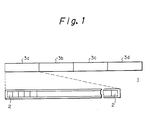
- a line thermal printer as shown in Fig. 1, for example, is available as this type of thermal printer.
- the print head 1 of this line thermal printer is struc-tured of 4 print blocks, 3a to 3d, whose heating element 2 of 320 dots per dot line has been divided at every 80 dots.
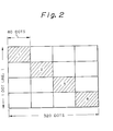
- thermosensitive paper position shade (1) corresponding to the print block 3a as shown in Fig. 2, and then the paper is fed out very slightly.
- the heating elements 2 in the print blocks 3b, 3c and 3c are sequentially electrified in a similar way, the printing is made on the thermosensitive paper positions (shaded areas (2), (3) and (4)) corresponding to the print blocks 3b, 3c and 3d, and thus the printing of 1 dot line is ended.
- this type of conventional line thermal printer has been structured such that the printer is electrified for the stipulated time with a high voltage of around 12 V, so if the printing has been made at every line with a low voltage, for example, from 4.8 V to 5.0 V, there is the problematic point that a favorable print quality or print density can not be obtained and the printing can not be made at a high speed as a result because the print energy is small.
- a low voltage for example, from 4.8 V to 5.0 V
- a favorable print quality or print density can not be obtained and the printing can not be made at a high speed as a result because the print energy is small.
- compact type portable equipment for example, a handy terminal and the like, needs to be driven by a low voltage, or by a single power source of around 4.8V, sufficient print energy can not be produced with this type of low voltage.
- an object of this invention is to present a thermal printer to print at high speed with the drive of low voltage of around 4.8 to 5 V while preventing the printing troubles attributable to the fall in voltage coming from the internal impedance and to the loss in head due to the common conductor inside the head, and moreover,
- thermosensitive papers it is another object to present a line thermal printer capable of obtaining the favorable print quality against a variety of thermosensitive papers while preventing the drop in print speed even in the case of low voltage, for example, of around 4.8 to 5.0 V.
- a line thermal printer relating to the present invention adopts the basic technical structure as follows so as to achieve the aforementioned objects.
- the 1st pattern relating to the line thermal printer of this invention it is a line thermal printer to print by electrically heating the print head having a plurality of heating elements to color a thermosensitive paper in contact with the said heating elements, which is equipped with a print head consisting of plural pieces of print block groups where the said plurality of heating elements have been subdivided at every stipulated quantity and with a heating means for electrically heating the said heating elements based on the stipulated data at every print block aforementioned, the said heating means constructed to simultaneously heat at least 2 print blocks which have been selected from the said print block groups, and as the 2nd pattern, it is a line thermal printer to print by electrically heating the print head having a plurality of heating elements to color a thermosensitive paper in contact with the said heating elements, which is not only equipped with a heating means for electrically heating the said heating elements based on the stipulated data against the applicable print head, but also
- the said thermal printer has a plurality of different printing modes, and may be structured such that the said heating means can change the number of said print blocks to be heated simultaneously and the pattern of heating elements to be heated on the basis of the said data in the said print blocks in accordance with the said printing mode, and it is effective to structure the thermal printer by installing a print percentage judgement means for judging the number of heating elements to be heated against the number of all the heating elements in the said print blocks based on the said data so that the said heating means may further divide and heat the said print blocks if the number of heating elements to be heated of said heating means should have exceeded the stipulated number by the applicable print percentage judgement means.
- the heating elements in a plurality of print blocks are simultaneously heated by the heating means, and thereby the printing is made on the thermosensitive paper. Namely, the printing can be accelerated even with the drive at a low voltage, for example, of around 4.8 V to 5.0 V.
- the print heads are further subdivided and heated by the heating means, and hence such printing troubles as reduction in voltage resulting from internal impedance and an internal heat loss in the head caused by a common conductor provided inside the head can be prevented.
- the printing troubles attributable to the reduction in voltage resulting from internal impedance and to the internal heat loss in the head caused by the common conductors provided inside the head can be prevented, and moreover the printing can be made at a high speed with the drive at low voltage of around 4.8 V to 5.0 V.
- the electrification to the print head is controlled with the print period being fixed by the electrification controlling means, the electrification cycles to the print head are determined on the basis of a plurality of printing modes in accordance with the kinds of thermosensitive papers, and the print energy per unit area is varied.
- the fall in print speed is prevented even with the drive at a low voltage, for example, of around 4.8 V to 5.0 V, and a favorable print quality can be obtained using a variety of thermosensitive papers.
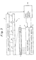
- Fig. 3 through Fig. 13 are diagrams showing a preferred embodiment of thermal printer relating to the 1st pattern of this invention.
- the print head 1 of thermal printer of this embodiment is structured of 5 print blocks 3a through 3e where the heating element 2 of 320 dots per dot line has been subdivided at every 64 dots.
- Numeral 4 is a heating means and Numeral 5 is a print percentage judgement means. Further, Numeral 6 is an electrification control means used in the 2nd pattern being described later.
- the heating means 4 is for flowing the current to the heating element 2 at print blocks 3a through 3e on the basis of the stipulated data, and the heating means 4 changes the number of print blocks 3a through 3e to be simultaneously heated and the pattern of heating element 2 to be heated in the print blocks 3a through 3e in accordance with a plurality of different printing modes which are described later.
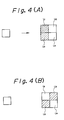
- the individual heating elements being used to the present invention are structured of a plurality of units U1 through Un (Fig. 4 shows an example of 4 heating elements) as shown by the example of Fig. 4, and each unit heating element is structured such that the heating is controlled individually and independently.
- the print percentage judgement means 5 is for dividing and heating the print blocks 3a through 3e to be heated by the heating means 4 if the number of unit heating elements to be heated among all of the unit heating elements 2 in each of the print blocks 3a through 3e, i.e., the print percentage, has become higher than the stipulated value, concretely for reducing the number of data to be printed in lump and for enlarging the print period.
- the heating element resistance value "R” must be decreased or the pulse width "t” must be enlarged in order to decrease the impressed voltage "V”. Therefore, to obtain the printing at a high speed with a low voltage considering the aforementioned in the present embodiment, the impressed voltage "V” is set to a value from 4.5 to 6.5 V, the heating element resistance value "R” to 45 ⁇ +/- 10%, the heating element area "S” to 6 head resolutions/mm, and the pulse width have been so set that the values may become W 0.165 mm x H 0.165 mm for 1-ply label paper and W 0.165 mm x H 0.330 mm for 2-ply paper.
- the present embodiment simultaneously heats the heating elements 2 in a plurality of print blocks 3a through 3e by the heating means 4.
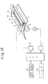
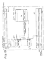
- the print unit of a line thermal printer relating to the present invention is structured of a sheet transfer means 8 consisting of the platen rollers, etc. being driven by a motor "M" for moving the paper and the like 7 which is a sheet to be printed in a given direction at the stipu-lated speed and at the stipulated pitch, and of the head 1 including the print block group 3 which has been constructed by further arranging in series the print blocks 3a, 3b, 3c, .
- a sheet transfer means controlling means 11 for controlling the said sheet transfer means 8 and a print block control means 12 for driving and controlling the print block of said print section are installed, and the said sheet transfer means controlling means 11 and the print block control means 12 are structured such that they are to be controlled by the central processing unit (CPU) 13 which is connected to the print data input instruction means 14 and the print data memory means 15 consisting, for example, of ROM where the stipulated print data are stored.
- CPU central processing unit
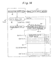
- control code CD is the information for designating the kinds of such mode, for example, as a high speed printing mode, a high quality printing mode and a double-density printing mode, and the flag and parameter set processing is executed in the said flag register 17 for transferal to the qualified data buffer 18-1 of data block 18.
- the said code buffer 19 has the buffers (20-1, 20-2), (21-1, 21-2) 7-8 (2n-1, 2n-2) for storing the qualified data and the code data against the respective data, and each of the data that have been transferred is to be stored into each of the buffers.
- the task units 22-1, 22-2, ... 22-n are storing individually a plurality of tasks (Task # 1 through Task # N) are arranged on the said task table 22.
- Each of these task units 22-1, 22-2, ... 22-n includes the functions responsive to each of the qualified data corresponding to such modes as the said high speed printing mode, high quality printing mode and double-density printing mode, and any of the tasks can be selected by discriminating the flag of qualified data owned by each data which has been transferred from the said code buffer 19.
- the task unit 22-2 incorporating the task #2 corresponding to the program for processing the said high speed printing mode, for example, is selected and the code data having the said data 1 is also transferred simultaneously to the applicable task unit 22-2.
- the code data owned by the said datal reads out the font data which has been stored into the applicable font address from the font table 24 of character generation (CG) in accordance with the font address owned by the said code data, returns it to the said task unit 22-2, processes at high speed printing mode the said font data which has been read out by the said task unit 22-2 in accordance with the program of qualified flag owned by the said task unit 22-2, and writes and stores its result into the image buffer 25.
- CG character generation
- the applicable image buffer 25 in the present invention includes, for example 2, image buffers 26 and 27, and the 1st image buffer 26 is for storing the print data of 1 line portion to be printed now whereas the 2nd image buffer 27 is for storing the print data of 1 line portion at a step before 1 line which is to be printed now.
- the applicable image buffer in this invention should not be limited to the buffer which combines 2 buffers, and needless to say, it may combine a plurality of image buffers of more than 3 pieces.
- the print control in this invention can adopt 32 dots, for example, in the double-density mode of letters and can adopt 16 dots in the usual mode.
- the print data for 1 line portion structuring 1 dot is to be stored into a single piece of image buffer, and moreover, in the present invention, the respective heating elements 2 of applicable print blocks are to be electrified for the printing in the stipu-lated timing on the basis of the print data which has been stored into the applicable image buffer, but the stipulated 1 line is divided into several times for its electrifica-tion, and 1 line is subdivided, for example, into 5 times for its electrification processing.
- the heating element 2 in this invention shall preferably be structured of 4 pieces of heating element units U1 through U4 as shown in Fig. 3 or Fig. 4.
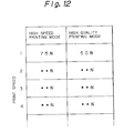
- the line thermal printer of this embodiment is provided with the following 4 kinds of modes
- the high speed printing mode adopts the so called 3 burn system where the heating elements 2 in the continuous 3 print blocks 3a through 3e are heated simultaneously by the heating means 4, and because of the 3 burns, the number of dots subjected to the simultaneous printing operation becomes greater.
- the printing can be made without any fall in the print speed as a whole.
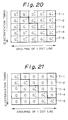
- the number of print dots in a horizontal direction is reduced by 50% in the high speed printing, and the relation of print data with actual print is such that, in the case of character printing mode, 2 picture elements in a vertical direction out of 2 x 2 matrix are printed against the data of 1 picture element as shown in Fig. 4(a), and in the case of the image printing mode, 2 picture elements in an oblique direction out of 2 x 2 matrix are printed against the data of 1 picture element as shown in Fig. 4(b).
- the electrification timing in this invention is indicated by T ( ⁇ , ⁇ ) as shown in Fig. 5, where the ⁇ of T ( ⁇ , ⁇ ) denotes the ⁇ th pulse while the ⁇ denotes the print block of ⁇ th group, while the asterisk * mark denotes the electrification of dot line at a step ahead.
- the present invention shows the example of electrifying the 1 line "l” 5 times when printing a single dot line " l", and the T-1 through T-5 in Fig. 5 are for dividing a single line "l" into 5 times to designate the number of blocks to be electrified during the occurrence T-1 of 1st pulse and to designate the number of blocks to be electrified during the occurrence T-2 of 2nd pulse, which is thereafter applicable in the same manner to T-3 through T-5.
- this invention adopts, as an embodiment, the adoption of 2 image buffers, and therefore, the 1st image buffer 26 which has stored the print data that is not to be printed on the line "l" and the 2nd image buffer 27 which has stored the print data that has been printed or is being printed into the line "l-1" at a step ahead of the said 1 line are laid out in Fig. 5.
- the print processing control of this invention has been structured such that, when one cycle of electrification control in 1 line "l" has been through, the sheet 7 to be printed is to be moved a slight distance by turning the motor M a slight angle on the basis of the control signal from the sheet transfer control means 11.
- the electrification timing in Fig. 5 is to be explained hereunder. First, if the 1st electrification pulse T-1 is generated, the current is carried to the block 3a of 1st image buffer 26 and to the blocks 3d and 3e in the 2nd image buffer 27 for individually heating the respective heating elements 2 that are included in the applicable blocks on the basis of the print data which have been stored into the said blocks.
- the current is carried to the blocks 3a and 3b of 1st image buffer 26 and to the block 3e in 2nd image buffer 27 for individually heating the respective heating elements 2 which are included in the said blocks on the basis of the print data that has been stored into the said blocks.
- the current is carried to the blocks 3a, 3b and 3c of 1st image buffer 26 for individually heating the respective heating elements 2 which are included in the said blocks on the basis of the print data that has been stored into the said blocks.
- the high speed printing mode in the present embodiment employs a 3-burn system for simultaneously electrifying 3 print blocks out of a plurality of print blocks (5 pieces in this embodiment) in the electrification processing of 1 print line, and thereby a high speed prin-ting can be realized.
- the high quality printing mode adopts the so called 2-burn system where the heating elements 2 in the continuous 2 print blocks 3a through 33 are simultaneously heated by the heating means 4, and because of the 2-burn, the print blocks which are adjacent among the print blocks 3a through 3e can be electrified at the same time.
- the relation of the print data with the actual printing is such that all the picture elements in 2 x 2 matrix are printed against the data of 1 picture element as shown in Fig. 6 in both the character printing mode and image printing mode.
- the electrification timing is indicated by T ( ⁇ , ⁇ ) as shown in Fig. 7, and the ⁇ of T ( ⁇ , ⁇ ) is the ⁇ th pulse while the ⁇ shows the print block of the ⁇ th group, and moreover, the asterisk * mark denotes the electrification of dot line at a step ahead.
- Fig. 7 The detailed explanation of Fig. 7 is to be omitted because it is identical to that of Fig. 5 excepting that the print block for electrification during the occurrence of 1 electrification pulse is two adjacent print blocks.
- the conventional system employs the method of sequentially driving them in the unit of 1 block.
- the coloring energy against the paper from the heating element must be supplied in one electrification.
- the present invention system reduces the width of standard electrification time to half in contrast with the said system and electrifies a plurality of adjacent blocks at a time. In this system, the printing can end in half the time of the conventional system.
- the coloring energy also tends to become larger as the print period becomes longer because the print period becomes shorter if the printing is made at a higher speed in accordance with this system, such a synergistic effect makes it appear that an efficient drive is possible by utilizing the heat accumulation effect.
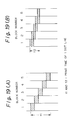
- Figs. 17(A) and (B) show the examples of the conventional printing method, which are identical to the structure of this invention such that 1 dot line is composed of 320 dots and is structured of 5 blocks including 64 dots each in 1 block, but in the conventional system in Fig. 17(A), only 1 block is electrified in a single electrification pulse, and hence there is the problem that a slight interval or gap is generated against the print data which has been printed during the generation of a previous electrification pulse (the pulse at a step 6 pulses ahead) and more over there is the problem that the volume of load required during the electrification at one time is great even if the next electrification pulse has come in the same block for electrification processing.
- Fig. 17(B) indicates an example of electrifying and processing 3 continuous blocks simultaneously with one electrification pulse but individually electrifying the respective residual print blocks in other electrification pulses, but even in this type of embodiment, there appears the problem that there is a slight interval between the print data which has been printed during the generation of previous electrification pulses and the data printed by the current electrification.
- the reduction printing mode is the mode for printing more printed digits in a line compared with the high speed printing mode, and the relation between the print data and the actual printing is for printing 3 picture elements against the data of 2 printing elements as shown in Fig. 8, while the relation of the print data "a” and “b” in Fig. 8 with the data " ⁇ ", " ⁇ and " ⁇ ” being printed in reduction is to be converted on the basis of such a principle as shown in Table 1.
- the electrification timing is set in the same timing as the high quality printing mode.
- the double density printing mode is the mode which becomes the number of print data of 320 dots/line, and the relation of the print data and the actual printing is for printing 1 picture element against the data of 1 picture as shown in Fig. 9, or the highest density printing becomes possible and therefore is the mode capable of printing the bar code and so forth.
- the electrification timing is set to the same mode as the high quality printing mode in a way similar to the reduction printing mode.
- the optimum printing can be made in accordance with each application by the said 4 operation modes, and the stabilization of print quality can be attempted by decreasing the influence in voltage drop due to impedance inside the battery by the print percentage judgement means 5.
- Fig. 16 shows the principle for enhancing the quality, namely the density of printing by using a plurality of burn systems according to the present invention.
- the N-th print block is to be electrified respectively in the electrification pulses F1 through F3 using the 3-burn system (See Fig. 16(B)).
- the conventional system electrifies a single print block "N" only once in 1 line portion, the print density distribution of print data alone can be obtained as shown in the shaded area of Fig. 16(C), and hence because a blank area exists against the adjacent print data, there is the drawback that the density looks thinner, while in this invention, because the same print block "N" is electrified 3 times continuously and moreover the printed sheet moves bit by bit during each electrification period, the print density as shown in Fig. (D) can be obtained where the density looks thicker.
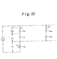
- Ro to R63 are the heating element resistors
- ro to r63 are lead resistors
- Rc is a common conductor resistance
- io to i63 are the heating element resistors and the current flowing to the lead resistors (hereinafter to be called the heating lead current)
- V Ro to V R63 are the voltages being impressed to the heating element resistors (hereinafter to be called the heating element voltages)
- Vro to Vr63 are the voltages being applied to the lead resistors (hereinafter to be referred to as the lead voltages)
- Vc is the voltage to be impressed to the common conductor resistor (hereinafter to be called the common voltage)
- ⁇ i is the current being flown to the common conductor resistor Rc (hereinafter to be named the common current) which becomes the total of heating lead currents io through i63.
- the A (i) is the variable by the influ-ence of such non-linear portion, internal transistor Tr section and the like, and the A (i) .
- ⁇ i inter relates to the number of electrified dots out of 64 dots of the heating element 2 of a single block among the print blocks 3a through 3e. Therefore, the Vc also becomes non-linear.
- the common conductor resistor Rc is non-linear, and the value of common conductor resistor Rc is changed by the number of electrification heating elements in one of print blocks 3a through 3e.
- the influence on the energy " ⁇ " becomes much greater because the value of heating element resistor Ro is small. This is because, if the value of the heating element resistor Ro is sufficiently large, the value of lead resistor "ro" is very much small, so the percetage against the entire resistor becomes small and its influence is less, but if the value of the heating element resistor Ro is small, a small value of the lead resistor "ro" becomes greater in the percentage against the entire resistor and its influence becomes greater.
- This automatic print percentage judgement is made on the high speed printing mode and the high quality printing mode by the print percentage judgement means 5.
- the number of dots in object is 96 dots (3-burn) in the case of the high speed printing and the said number is 128 dots (2-burn) in the case of the high quality printing mode
- the print percentage in this number of dots should exceed a certain percentage (for example 75% in the case of hight speed printing mode)
- the number of divisions of heating element 2 in the print blocks 3a through 3e is increased and the cycles of electrification are decreased. the fractionization to be done at this time results in dropping the print speed, which promotes the diffusion of energy (heat) from the print head.
- the heating elements in a plurality of print blocks are heated simultaneously for printing the letters on the thermosensitive paper in this embodiment. That is to say, the printing can be made at a higher speed, for example, even with the drive at low voltage of around 5V.
- the printing troubles attributable to the voltage drop due to the internal impedance and to the loss inside the drop by the common conductor inside the head can be prevented, and moreover the printing can be made at a high speed even with the drive of low voltage of around 5V.
- the said embodiment has been explained in the case of the print head with its total number being 320 dots having a heating element which has been subdivided into 5 print blocks at every 64 dots, but without being limited by this, the total number of heating elements and the number of subdivisions of a heating element into the print blocks owned by the print head are, needless to say, optional in accordance with the given equipment and purpose.
- the basic structure of this embodiment is almost identical to the structure in Fig. 3 on the line thermal printer relating to the 1st pattern.
- this embodiment utilizes the electrification control means 6 which is shown in Fig. 3.
- the electrification control means 6 in this embodiment is for controlling the electrification to the print head 1 by the heating means 4 and for deciding the cycle of electrifications to the print head 1 on the basis of a plurality of printing modes in accordance with the kinds of thermosensitive paper with the printing cycle being fixed, namely, with the feed of thermosensitive paper being stopped.
- the print head 1 may be structured of a plurality of print blocks 3a through 33 by collecting the heating elements 2 at the stipulated quantity for their blocking, and it may also be structured for selecting a plurality of print blocks out of the respective blocks for their electrification at the same time as shown in Fig. 3.
- the present embodiment has been set such that the impressed voltage is 4.8V, the heating element resistance value is 45 ⁇ +/- 10%, the heating element area S is W 0.165 mm x H 0.165 mm for 1-ply label paper and W 0.165mm x H 0.165mm or W 0.165 mm x H 0.330 mm for 2-ply paper with the head resolution being 6/mm. This is substantially the same conditions as those of the 1st pattern.
- this embodiment to heat the heating elements 2 simultaneously in a plurality of print blocks 3a through 3e by use of the heating means 4.
- the line thermal printer of this embodiment is equipped with 2 kinds of mode, which are
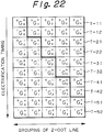
- G b/a stands for a group and the "b" for an electrification timing
- the area enclosed by a thick line frame denotes the electrification timing of a previous dot line.
- the group of (G 0/0 , G 4/1 , G 3/2 , G 2/3 , G 1/4 ) means that the 1st electrification of Group O, the 5th electrification of Group 1, the 4th electrification of Group 2, the 3rd electrification of Group 3 and the 2nd electrification of Group 4 of the current line are to be made at the same time.
- the 2-dot line should be used as a single heating line, the resolution in feed direction of thermosensitive paper falls compared with that in the 1-ply printing mode, namely there appears a gap between the previous dot line and the subsequent dot line, but because the print energy ⁇ becomes larger, the printed dot becomes larger than in the 1-ply printing mode, and is sufficiently practicle, the printing speed is preferred in this embodiment. In this case, a high quality print can be obtained by lowering the speed if the said quality is required.
- the 2-ply printing mode requires a higher print energy ⁇ compared with the in 1-ply printing mode, and it becomes the electrification pattern as shown in Fig. 22.
- thermosensitive paper for example, if 2 sheets of thermosensitive paper should be printed in overlap, the print energy is accordingly required compared with the printing of 1 sheet, and for the need of increasing the energy given to the respective heating elements 2, the embodiment in question is for solving the said type of problem by increasing the cycles of electrification.
- the additional electrification is done at the electrification pulse generation point of time T-n2 against each electrification pulse generation point of time T-n1.
- the electrification time in this type of additional electrification is not to be especially limited, but is appropriately determined by the kind, the number of sheets of thermosensitive paper, the print speed, etc.
- the ratio of applicable additional electrification time can be made to be 0.5.
- the present embodiment also uses the said print percentage judgement means 6 when conducting the usual electrification processing or when conducting the additional electrification, and if the print percentage of each heating element 2 in a single piece of print block has exceeded the stipulated value, for example 50%, the electrification time against each block in 1 line can further be subdivided.
- the electrification dots of 1 print line are to be electrified in division at every 1 dot in the doubledensity mode.
- the printing/coloring energy is proportional to the square of impressed voltage as described above.
- the line thermal printer relating to the present invention adopts the system for dividing the print block in order to avert the said type of problematic point, and the method counts the number of electrification dots inside the block in object of electrification as shown in the above, and divides the print block in accordance with the number of said dots that have been counted to decide the division of 1/2 or the division of 1/4.
- the print block in object is shifted to the next print block for carrying out a similar actuation.
- the threshold value of the number of dots for deciding the division electrification varies with the current capacity of the power source (battery) to be used.
- the print percentage is low, the data inside a single print block can be printed at a time without any division.
- the print percentage is slightly high, it may be acceptable to use the method for dividing the dots inside a print block in terms of software within the said print block and for printing the data with the time being deviated sequentially.
- the total dots inside a print block shall be divided into 1/4 in terms of software from one end, for printing the data sequentially.
- the present embodiment can control the current load against the battery and can obtain a stable print quality by changing the division percentage of print data for printing the data on the basis of print percentage.
- the optimum printing is done in accordance with each application by the said 2 actuation modes, and the stabilization of print quality can be attempted through decreasing the influence of voltage drop due to the impedance inside the battery by the print percentage judgement means 5.
- the electrification to the print head can be controlled with the print period fixed by use of the electrification control means, the cycle of electrification to the print head can be determined on the basis of a plurality of printing modes according to the kinds of thermosensible papers, thus being able to change the print energy per unit area.
- thermosensitive paper Therefore, the fall in printing speed can be prevented even in the drive with a low voltage, for example, of around 4.8 V, and a favorable print quality can be obtained against various types of thermosensitive paper.
- the data can be printed out in dense/thin gradation by controlling the cycles of electrification as found in the present embodiment.
- the said embodiment quotes an example of the print head of 320 dots in total number which has a heating element divided into 5 print blocks at every 64 dots, but without being limited only to this case, it is apparent that the total number of heating elements owned by the print head and the number of divisions of heating element into print blocks are optional in accordance with the given equipment and purpose.
- cycles of electrification can be determined freely without being limited to the said embodiment.
- the line thermal printer relating to this invention is for receiving the print data inclusive of the stipulated character code, etc. which has been input from an appropriate input means with the computer 13 which is a central processing means, and for printing the font data corresponding to the applicable character stored inside the said computer 13 onto the printing sheet, but the printing of high resolution has become possible following the enhancement in recent manufacturing techniques of said thermal line head.
- the standard letter size has been programmed to be printed by extending one dot 2 times in vertical x 2 times in horizontal directions as explained in the above.
- the printing is made without any reduction processing after the said extension conversion has been executed in the high quality printing mode (HQ), and in this case the print percentage tends to become higher than the print percentage prior to the extension conversion.
- HQ high quality printing mode
- the high speed printing mode executes the reduction processing (thinning out the print dots) in vertical and horizontal direction after the said extension conversion for reducing the actual print percentage.
- the print speed can become higher because the print percentage in each divided block in the print block is frequently falling under the threshold value of the print percentage judgement compared with the print percentage in a high quality printing mode (HQ).
- the print density becomes thinner as a whole because the number of print dots decreases.
- Step (1) the data of 1 line portion inside the stipulated print data to be printed is first input into the reception means of a computer which is a central processing means from an appropriate input means 14, and the said print data is taken into a reception buffer 15. (Step (2)).
- Step (3) the respective plural input data of print data which have been input by a data analysis means 16 are analyzed, and the control code having the said print data judges (Step (4)) such information as print mode and the like via the qualified data processing means structured of flag register 17 and so forth and stores the said qualified data into the qualified data buffers (20-1 through 20-N) corresponding respectively to the said input data of code buffer 19.
- Step (3) the print data owned by the said print data are separated and processed adequately by the print data control means (Step (5)), and the code data which are the result thereof are stored into the respective corresponding code data buffers (21-1 through 21-N) of applicable input data in the code buffer 19 via the data block 18. (Step (6)).
- the coder buffer of print data of 1 line portion to be printed is completed by the said Step (6).
- the qualified data is first read out on each of these data in this type of code buffer 19 to make a judgement and determine which type of print mode code is owned (Step (7)).
- the stipulated task unit (for example, Task Unit #1) 22-1 is selected from the task table 22.
- the qualified data and code data of stipulated data which are stored into the said coder buffer 19 are transferred to the said selected task unit #1 (Step (8)), read out from the stipulated print data from the applicable CG font table 24 in accordance with the code address owned by the said code data using the print data read means 81 and the CG font data retrieval means 82 which are incorporated into the said task unit #1, determines the printing mode and finally converts into the stipulated form the print data using the print data conversion means 83, which have been retrieved by use of the printing mode program based on the said qualified data retrieval.
- Step (9) the print data which have been converted in the said task unit are transferred into an image buffer 25 and the print data which have been converted on each of these print data are to be stored into the stipulated buffer positions.
- Step (10) the number of heating elements 2 being electrified on the basis of print data inside the said image buffer 25 is operated and the print percentage is calculated for every print block.
- Step (11) If the said print percentage is larger than the stipu-lated threshold value, the step proceeds to Step (11), and the said print data are to be further subdivided inside the print block.
- Step (12) the said step proceeds to Step (12) without passing through the said Step (11).
- the cycles of electrification time are determined in accordance with the printing mode being decided by the kind, number, etc. of thermosensitive paper.
- the print data which have been processed at Step (12) are transferred to the print head 1 via the print head data transfer means contained in the print block control means 12.
- the said print head is structured of the latch circuits 201 through 20n which have been connected respectively to a plurality of heating elements 2 and the flip flops 101 through 10n connected to the said latch circuits but the said heating elements 2 are also driven by the heating means included in the said print block control means 12 via the respective drive circuits 301 through 30n.
- the latch control signals inside the said print data are supplied to the said latch circuits, and the serial data transmission signals are supplied to the said flip flop circuits.
- thermosensitive paper The print speed, print voltage, print temperature, print percentage, printing mode and kind and number of thermosensitive paper is judged from the said print data at Step (14), the drive conditions of electrification time control means is operated at Step (15) on the basis of the said result, and the heating means included in the said print block control means 12 is driven on the basis of the output of the said Step (15) at Step (16) for individually driving the stipulated heating elements 2.
- the stipulated data is output from the print paper transfer means 11 on the basis of the said print data, for driving the motor to transfer the sheets to be printed and for turning by the stipulated angle the platen roller 8 which is the said printed sheet transferring means to move the print sheet the stipulated distance.
- the heating elements in a plurality of print blocks are heated at the same time for printing the data on the thermosensitive paper.
- the printing can be made at a high speed even with the drive at low voltage, for example, of around 5V.
- the print block is further subdivided into several blocks for heating by the heating means, thereby capable of preventing printing problems such as voltage drop due to internal impedance and the loss inside the head coming from the common conductor inside the head.
- the present invention can control the electrification to the print head with the print period being fixed by the electrification control means, determine the cycles of electrification to the print head on the basis of a plurality of printing modes in accordance with the kind of thermosensitive paper and change the printing energy per unit area.
- the drop in print speed can be prevented even with the drive at a low voltage, for example, of around 4.8V, and a favorable print quality can be obtained against a variety of thermosensitive paper.
Landscapes
- Engineering & Computer Science (AREA)
- General Engineering & Computer Science (AREA)
- Physics & Mathematics (AREA)
- General Physics & Mathematics (AREA)
- Theoretical Computer Science (AREA)
- Electronic Switches (AREA)
Applications Claiming Priority (4)
| Application Number | Priority Date | Filing Date | Title |
|---|---|---|---|
| JP26272790 | 1990-09-28 | ||
| JP262728/90 | 1990-09-28 | ||
| JP262727/90 | 1990-09-28 | ||
| JP26272890 | 1990-09-28 |
Publications (3)
| Publication Number | Publication Date |
|---|---|
| EP0478369A2 true EP0478369A2 (fr) | 1992-04-01 |
| EP0478369A3 EP0478369A3 (en) | 1992-10-28 |
| EP0478369B1 EP0478369B1 (fr) | 1997-06-18 |
Family
ID=26545674
Family Applications (1)
| Application Number | Title | Priority Date | Filing Date |
|---|---|---|---|
| EP91308861A Expired - Lifetime EP0478369B1 (fr) | 1990-09-28 | 1991-09-27 | Imprimante thermique travaillant ligne par ligne |
Country Status (3)
| Country | Link |
|---|---|
| US (1) | US5319390A (fr) |
| EP (1) | EP0478369B1 (fr) |
| DE (1) | DE69126590T2 (fr) |
Cited By (8)
| Publication number | Priority date | Publication date | Assignee | Title |
|---|---|---|---|---|
| FR2693680A1 (fr) * | 1992-06-23 | 1994-01-21 | Kyocera Corp | Tête thermique et procédé pour la piloter. |
| EP0698491A3 (fr) * | 1994-08-24 | 1996-06-26 | Canon Kk | Procédé et appareil d'enregistrement d'images |
| GB2304951A (en) * | 1995-08-25 | 1997-03-26 | Esselte Dymo Nv | Tape printing apparatus and print head |
| EP0809196A1 (fr) * | 1996-05-24 | 1997-11-26 | Brother Kogyo Kabushiki Kaisha | Appareil d'impression capable d'imprimer des caractères embellis avec une partie vide |
| US5826994A (en) * | 1995-08-25 | 1998-10-27 | Esselte Nv | Tape printing apparatus |
| EP1127697A3 (fr) * | 2000-02-21 | 2001-11-21 | Alps Electric Co., Ltd. | Méthode de contrôle de l'alimentation en courant dans une tête thermique en ligne |
| US8803932B2 (en) | 2010-09-30 | 2014-08-12 | Brother Kogyo Kabushiki Kaisha | Printer |
| EP3369580A3 (fr) * | 2017-03-03 | 2018-11-07 | Fujitsu Component Limited | Imprimante |
Families Citing this family (1)
| Publication number | Priority date | Publication date | Assignee | Title |
|---|---|---|---|---|
| US20030156129A1 (en) * | 1991-12-25 | 2003-08-21 | Tsutomu Takahashi | Information processing method and apparatus |
Family Cites Families (18)
| Publication number | Priority date | Publication date | Assignee | Title |
|---|---|---|---|---|
| JPS5334412A (en) * | 1976-09-13 | 1978-03-31 | Toshiba Corp | Memory unit |
| US4140022B1 (en) * | 1977-12-20 | 1995-05-16 | Hewlett Packard Co | Acoustic imaging apparatus |
| JPS54155683A (en) * | 1978-05-30 | 1979-12-07 | Matsushita Electric Industrial Co Ltd | Electronic scanning system ultrasoniccwave tomooinspection device |
| JPS5779761A (en) * | 1980-11-05 | 1982-05-19 | Sony Corp | Drive method for thermo-sensing picture display device |
| JPS59123683A (ja) * | 1982-12-28 | 1984-07-17 | Brother Ind Ltd | サ−マルプリンタ |
| JPS6044371A (ja) * | 1983-08-20 | 1985-03-09 | Ricoh Co Ltd | サ−マルヘツドの駆動方法 |
| JPS60168669A (ja) * | 1984-02-14 | 1985-09-02 | Fuji Xerox Co Ltd | サ−マルヘツド駆動装置 |
| JPH0761117B2 (ja) * | 1984-08-31 | 1995-06-28 | 富士ゼロックス株式会社 | 感熱記録方法および装置 |
| US4699009A (en) * | 1985-11-05 | 1987-10-13 | Acuson | Dynamically focused linear phased array acoustic imaging system |
| DE3603042A1 (de) * | 1985-12-02 | 1987-08-06 | Siemens Ag | Ultraschallgeraet mit dynamischer veraenderung der empfangsfokuslage |
| JPS62138289A (ja) * | 1985-12-13 | 1987-06-22 | Victor Co Of Japan Ltd | プリント方法 |
| US4875056A (en) * | 1986-01-17 | 1989-10-17 | Canon Kabushiki Kaisha | Thermal recording apparatus with variably controlled energization of the heating elements thereof |
| JPS62299350A (ja) * | 1986-06-18 | 1987-12-26 | Fujitsu Ltd | サ−マルヘツド駆動制御方式 |
| JPS6327271A (ja) * | 1986-07-18 | 1988-02-04 | Shinko Electric Co Ltd | 熱転写式プリンタ |
| JPH0790642B2 (ja) * | 1987-02-25 | 1995-10-04 | 株式会社リコー | サ−マルプリンタ |
| JPH022023A (ja) * | 1988-06-10 | 1990-01-08 | Minolta Camera Co Ltd | サーマルプリンタ |
| JPH02258355A (ja) * | 1989-03-31 | 1990-10-19 | Toshiba Corp | 電子機器 |
| JPH03104660A (ja) * | 1989-09-19 | 1991-05-01 | Fujitsu Ltd | サーマルプリンタ |
-
1991
- 1991-09-27 DE DE69126590T patent/DE69126590T2/de not_active Expired - Lifetime
- 1991-09-27 US US07/766,135 patent/US5319390A/en not_active Expired - Lifetime
- 1991-09-27 EP EP91308861A patent/EP0478369B1/fr not_active Expired - Lifetime
Cited By (11)
| Publication number | Priority date | Publication date | Assignee | Title |
|---|---|---|---|---|
| FR2693680A1 (fr) * | 1992-06-23 | 1994-01-21 | Kyocera Corp | Tête thermique et procédé pour la piloter. |
| EP0698491A3 (fr) * | 1994-08-24 | 1996-06-26 | Canon Kk | Procédé et appareil d'enregistrement d'images |
| US6155663A (en) * | 1994-08-24 | 2000-12-05 | Canon Kabushiki Kaisha | Image recording method and apparatus |
| GB2304951A (en) * | 1995-08-25 | 1997-03-26 | Esselte Dymo Nv | Tape printing apparatus and print head |
| US5826994A (en) * | 1995-08-25 | 1998-10-27 | Esselte Nv | Tape printing apparatus |
| EP0809196A1 (fr) * | 1996-05-24 | 1997-11-26 | Brother Kogyo Kabushiki Kaisha | Appareil d'impression capable d'imprimer des caractères embellis avec une partie vide |
| US5855440A (en) * | 1996-05-24 | 1999-01-05 | Brother Kogyo Kabushiki Kaisha | Printing apparatus capable of printing character having embellishment with blank portion |
| EP1127697A3 (fr) * | 2000-02-21 | 2001-11-21 | Alps Electric Co., Ltd. | Méthode de contrôle de l'alimentation en courant dans une tête thermique en ligne |
| US6417877B2 (en) | 2000-02-21 | 2002-07-09 | Alps Electric Co., Ltd. | Current supply control method for line thermal head |
| US8803932B2 (en) | 2010-09-30 | 2014-08-12 | Brother Kogyo Kabushiki Kaisha | Printer |
| EP3369580A3 (fr) * | 2017-03-03 | 2018-11-07 | Fujitsu Component Limited | Imprimante |
Also Published As
| Publication number | Publication date |
|---|---|
| EP0478369A3 (en) | 1992-10-28 |
| EP0478369B1 (fr) | 1997-06-18 |
| US5319390A (en) | 1994-06-07 |
| DE69126590D1 (de) | 1997-07-24 |
| DE69126590T2 (de) | 1997-10-02 |
Similar Documents
| Publication | Publication Date | Title |
|---|---|---|
| AU637079B2 (en) | Thermal print head control for printing serial bar codes | |
| JP6489431B2 (ja) | サーマルプリンタ、制御方法及びプログラム | |
| EP0396982B1 (fr) | Dispositif d'enregistrement et procédé d'enregistrement | |
| US5319390A (en) | Thermal printer apparatus | |
| AU691822B2 (en) | Thermal printer control system | |
| EP0551095A1 (fr) | Imprimante sérielle d'images tramées et méthode de mise en oeuvre | |
| US4656489A (en) | Thermal printer/plotter | |
| EP0150038B1 (fr) | Dispositif d'impression par points | |
| EP0253200A2 (fr) | Dispositif de décalage de la tête d'impression pour égaliser l'usure | |
| US4988221A (en) | Specific data input order for continuous strips of tags including line spacing amount | |
| JPH01218851A (ja) | ドットマトリクス式プリンタ | |
| US4488827A (en) | Continuous vertical line print control system | |
| EP0114989B1 (fr) | Imprimante thermiqueet procédé d'impression thermique | |
| US5099258A (en) | Dot print density regulating circuit | |
| JP3074575B2 (ja) | サーマルプリンタ | |
| EP0193343A1 (fr) | Imprimante thermique | |
| EP0262506B1 (fr) | Impression thermique en deux étapes | |
| EP0429071A2 (fr) | Tête thermique et appareil pour le transfert thermique | |
| JPH06143648A (ja) | サーマルプリンタ装置 | |
| JPH07323597A (ja) | 印刷装置 | |
| JPH0616764Y2 (ja) | ドットマトリクスプリンタ | |
| JPH09169131A (ja) | マルチラインサーマルプリンタの転送制御方式 | |
| JP2645170B2 (ja) | ラインプリンタの印字方法 | |
| JP2001315372A (ja) | 印刷装置および印刷方法 | |
| KR930008065B1 (ko) | 프린터의 10진수 인자방법 |
Legal Events
| Date | Code | Title | Description |
|---|---|---|---|
| PUAI | Public reference made under article 153(3) epc to a published international application that has entered the european phase |
Free format text: ORIGINAL CODE: 0009012 |
|
| AK | Designated contracting states |
Kind code of ref document: A2 Designated state(s): DE FR GB |
|
| PUAL | Search report despatched |
Free format text: ORIGINAL CODE: 0009013 |
|
| AK | Designated contracting states |
Kind code of ref document: A3 Designated state(s): DE FR GB |
|
| 17P | Request for examination filed |
Effective date: 19930421 |
|
| 17Q | First examination report despatched |
Effective date: 19941206 |
|
| GRAG | Despatch of communication of intention to grant |
Free format text: ORIGINAL CODE: EPIDOS AGRA |
|
| GRAH | Despatch of communication of intention to grant a patent |
Free format text: ORIGINAL CODE: EPIDOS IGRA |
|
| GRAH | Despatch of communication of intention to grant a patent |
Free format text: ORIGINAL CODE: EPIDOS IGRA |
|
| GRAA | (expected) grant |
Free format text: ORIGINAL CODE: 0009210 |
|
| AK | Designated contracting states |
Kind code of ref document: B1 Designated state(s): DE FR GB |
|
| REF | Corresponds to: |
Ref document number: 69126590 Country of ref document: DE Date of ref document: 19970724 |
|
| ET | Fr: translation filed | ||
| PLBE | No opposition filed within time limit |
Free format text: ORIGINAL CODE: 0009261 |
|
| STAA | Information on the status of an ep patent application or granted ep patent |
Free format text: STATUS: NO OPPOSITION FILED WITHIN TIME LIMIT |
|
| 26N | No opposition filed | ||
| REG | Reference to a national code |
Ref country code: GB Ref legal event code: IF02 |
|
| REG | Reference to a national code |
Ref country code: GB Ref legal event code: 732E |
|
| REG | Reference to a national code |
Ref country code: FR Ref legal event code: TP |
|
| PGFP | Annual fee paid to national office [announced via postgrant information from national office to epo] |
Ref country code: FR Payment date: 20100921 Year of fee payment: 20 |
|
| PGFP | Annual fee paid to national office [announced via postgrant information from national office to epo] |
Ref country code: GB Payment date: 20100922 Year of fee payment: 20 |
|
| PGFP | Annual fee paid to national office [announced via postgrant information from national office to epo] |
Ref country code: DE Payment date: 20100922 Year of fee payment: 20 |
|
| REG | Reference to a national code |
Ref country code: DE Ref legal event code: R071 Ref document number: 69126590 Country of ref document: DE |
|
| REG | Reference to a national code |
Ref country code: DE Ref legal event code: R071 Ref document number: 69126590 Country of ref document: DE |
|
| REG | Reference to a national code |
Ref country code: GB Ref legal event code: PE20 Expiry date: 20110926 |
|
| PG25 | Lapsed in a contracting state [announced via postgrant information from national office to epo] |
Ref country code: GB Free format text: LAPSE BECAUSE OF EXPIRATION OF PROTECTION Effective date: 20110926 |
|
| PG25 | Lapsed in a contracting state [announced via postgrant information from national office to epo] |
Ref country code: DE Free format text: LAPSE BECAUSE OF EXPIRATION OF PROTECTION Effective date: 20110928 |