EP0478425B1 - Vorrichtung zur Erzeugung von mehreren Lichtstrahlen - Google Patents
Vorrichtung zur Erzeugung von mehreren Lichtstrahlen Download PDFInfo
- Publication number
- EP0478425B1 EP0478425B1 EP91402506A EP91402506A EP0478425B1 EP 0478425 B1 EP0478425 B1 EP 0478425B1 EP 91402506 A EP91402506 A EP 91402506A EP 91402506 A EP91402506 A EP 91402506A EP 0478425 B1 EP0478425 B1 EP 0478425B1
- Authority
- EP
- European Patent Office
- Prior art keywords
- generating device
- selective mirrors
- light
- selective
- window
- Prior art date
- Legal status (The legal status is an assumption and is not a legal conclusion. Google has not performed a legal analysis and makes no representation as to the accuracy of the status listed.)
- Expired - Lifetime
Links
- 238000001228 spectrum Methods 0.000 claims description 4
- 230000003595 spectral effect Effects 0.000 description 4
- 239000003086 colorant Substances 0.000 description 3
- 239000011521 glass Substances 0.000 description 2
- 239000011159 matrix material Substances 0.000 description 2
- 230000003287 optical effect Effects 0.000 description 2
- PLXMOAALOJOTIY-FPTXNFDTSA-N Aesculin Natural products OC[C@@H]1[C@@H](O)[C@H](O)[C@@H](O)[C@H](O)[C@H]1Oc2cc3C=CC(=O)Oc3cc2O PLXMOAALOJOTIY-FPTXNFDTSA-N 0.000 description 1
- 230000001154 acute effect Effects 0.000 description 1
- 238000007796 conventional method Methods 0.000 description 1
- 239000004973 liquid crystal related substance Substances 0.000 description 1
Images

Classifications
-
- G—PHYSICS
- G02—OPTICS
- G02B—OPTICAL ELEMENTS, SYSTEMS OR APPARATUS
- G02B27/00—Optical systems or apparatus not provided for by any of the groups G02B1/00 - G02B26/00, G02B30/00
- G02B27/10—Beam splitting or combining systems
- G02B27/14—Beam splitting or combining systems operating by reflection only
- G02B27/143—Beam splitting or combining systems operating by reflection only using macroscopically faceted or segmented reflective surfaces
-
- G—PHYSICS
- G02—OPTICS
- G02B—OPTICAL ELEMENTS, SYSTEMS OR APPARATUS
- G02B27/00—Optical systems or apparatus not provided for by any of the groups G02B1/00 - G02B26/00, G02B30/00
- G02B27/10—Beam splitting or combining systems
- G02B27/1006—Beam splitting or combining systems for splitting or combining different wavelengths
Definitions
- the invention relates to a device producing simultaneously several beams of light corresponding to different spectral domains.
- the invention applies particularly (but not exclusively) to the lighting of spatial light modulation screens in color image projectors.
- the image to be projected is formed on the surface of the spatial light modulator screen, the latter generally consisting of a liquid crystal matrix cell.
- the light provided by a light source is spatially modulated by the matrix, and the projected image results from this modulation.
- the low light output of image projectors is linked to various causes, one of which is the loss of light due to the differences between the shape of the screen. spatial modulator to be illuminated and the shape of the section of the light beam coming from the light source.
- the image is provided with a 16/9 format (ratio of length to width).
- An image projector system meeting this definition uses a spatial modulator screen having this 16/9 format.
- the fraction of light energy used to illuminate the rectangle that constitutes the spatial modulator screen corresponds only to the SR / SF ratio of the SR surface of this rectangle to the SF surface of the beam section, that is 0.54 in the best case, that is to say when SR is as large as possible, in format 16 / 9, while being contained in SF.
- the present invention provides a new arrangement of the light source and means which separate the white light beam or primary beam, into several secondary beams each having a different spectral range and a rectangular section.
- the invention is advantageously applied when at least two secondary beams are necessary, particularly with a 16/9 format, whatever the shape of the section of the primary beam, and its use in particular in color video projectors makes it possible to very interestingly improve the light efficiency of the latter.
- a device for generating light beams comprising a light source producing a light beam called the primary beam, the spectrum of which substantially covers that of visible light, a light separator, of the type comprising at least two selective mirrors in wavelength, illuminated by the primary beam and producing in return at least two secondary beams corresponding to different wavelengths, the first and the second of the secondary beams being obtained using respectively of a first and of a second of said wavelength selective mirrors, is characterized in that the first and second selective mirrors are arranged so as to intercept different parts of the section of the primary beam, and in that the light separator further comprises a rear face constituting at least partially a total mirror, the rear face being on the one hand located opposite the light source with respect to the first and second selective mirrors, and being on the other hand in a plane perpendicular to an axis of propagation of the primary beam.
- Figure 1 shows by way of nonlimiting example a device 1 for generating light beams according to the invention.
- the generator device 1 comprises a light source 2 producing a light beam called the primary beam FP.
- the primary beam FP is intended to generate several secondary beams and its spectrum must cover the spectral domains of these secondary beams.
- the spectrum of the primary beam FP corresponds substantially to that of visible light, so as to allow the production of three secondary beams F1, F2, F3 monochrome, the one for blue, another for red and the third for green.
- the primary beam FP is a beam with substantially parallel rays, as obtained with light sources of white light currently commercially available, of the type comprising a parabolic reflector by example.
- a conventional source S of white light placed between a spherical reflector 4 and a collimating lens LC and on the optical axis 5 of the latter, at the center of curvature of the spherical reflector and focal point of the LC lens.
- the source S produces a light 3 collimated by the lens LC so as to form the primary beam FP; the optical axis of the collimating lens constituting the axis of propagation 5 of the primary beam FP.
- the primary beam FP propagates in the direction of a light separating device SL of the type comprising several wavelength selective mirrors, each selective mirror being reflective for a given wavelength.
- a light separating device SL of the type comprising several wavelength selective mirrors, each selective mirror being reflective for a given wavelength.
- Such selective mirrors exist in dichroic cubes (commonly available commercially), which in particular allow on the one hand to reflect two beams of different colors (blue and red for example) in opposite directions, and on the other hand to transmit a third beam of a third color, green for example.
- the light separator SL comprises first and second wavelength selective mirrors M1, M2, interposed on the path of the primary beam FP so that each selective mirror intercepts a part SF1, SF2 different from the FP primary beam section.
- the first mirror M1 for example reflects the wavelengths which correspond to the blue with which it produces a first secondary beam F1; and the second selective mirror M2 reflects for example the wavelengths which correspond to red, with which it produces a second secondary beam F2.
- the light separator SL further comprises a rear face 15 at least partially reflecting all the wavelengths, arranged opposite the light source 2 with respect to the first and second selective mirrors M1, M2.
- the rear face 15 comprises a window 6 intended to transmit a third secondary beam F3.
- the first and second selective mirrors M1, M2 as well as the rear face 15 are carried by a block 16 transparent to light (in glass for example), forming a prism with triangular section seen in the figure 1 according to its section; the rear face 15 being on the hypotenuse face of the prism, the 2 selective mirrors M1, M2 being on the two other faces.
- a first and a second transparent part 7, 8 are applied respectively to the first and the second selective mirrors M1, M2 in order to avoid large angles of refraction at the level of the selective mirrors M1, M2.
- the shape of these parts 7, 8 is such that their entry face respectively 12, 13 and their exit face 16, 17 are normal to the incident and emerging rays respectively.
- the first and second selective mirrors M1, M2, seen from the light source 2 each have an apparent surface SA rectangular.
- the two selective mirrors M1, M2 are inclined on the axis of propagation 5, with which they preferably (but not necessarily) form angles of inclination a1, a2 equal; the apparent surface SA being equal to the real surface SR multiplied by the sine of the angle of inclination a1, a2.
- first and second selective mirrors respectively reflect a first and a second secondary beam F1, F2 corresponding to blue and red, and the section of each of these two secondary beams is equal to the apparent surface of the selective mirror having generated it. .
- the invention finds one of its most interesting applications when each secondary beam F1, F2 is given a rectangular section in 16/9 format; this is because such formats placed one beside the other constitute an almost square surface.
- the first and second selective mirrors M1, M2 are arranged side by side, their length is in a plane perpendicular to that of the figure and their width 11, 12 is greater than their apparent width 11 ′, 12 ′ views from the light assembly 2. If their width 11, 12 is such that, as a function of the angles of inclination a1, a2, their apparent width 11 ′, 12 ′ gives them an apparent surface in 16/9 format, the surface total of the intercepted section of the primary beam FP by the two selective mirrors M1, M2 is close to a square.
- the ratio of the quantity of energy withdrawn to the quantity of energy available in the primary beam FP is improved.
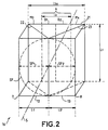
- Figure 2 is a perspective view of the block or prism 16, which illustrates the registration of selective mirrors in the section of the primary beam FP.
- the first and second selective mirrors M1, M2 and the rear face 15 are not materialized in FIG. 2, but they are represented respectively by a first and a second face 22, 23 and a hypothenous face 21 of the prism 16 which carries them: the first selective mirror M1 being on the face 22; the second mirror M2 being on the face 23, and the rear face 15 being on the hypotenuse face 21.
- These mirrors or faces all have the same length L1 given by a height of the prism 16.
- the first and second transparent parts 7, 8 are applied respectively against the faces 22 and 23 of the prism 16 and have the same length L1 as the latter; the input faces 12, 13 of these parts are normal to the axis of propagation 5 of the primary beam FP.
- the primary beam FP has a circular cross section which is shown in FIG. 2 by a circle SF in dotted lines. It is observed that the two entry faces 12, 13 (each in 16/9 format) arranged side by side add their width 11 ′, 12 ′ to form an almost square surface inscribed in the section of the primary beam FP.
- the first and second entry faces 12, 13 have the same surface and the same format as the selective mirrors M1, M2 and these entry faces 12, 13 intercept respectively the first and the second part SF1, SF2 of the section of the primary beam FP.
- the rear face 15 comprises the window 6 already mentioned as well as a third and a fourth mirror M3, M4 arranged on either side of this window 6.
- the window 6 has a length L1 equal and parallel to the length of the faces 12, 13 of the parts 7, 8, that is to say equal to the length of the first and second selective mirrors M1, M2; and its width 13 is equal to the apparent widths 11 ′, 12 ′ of the latter while the rear face 15 has a width 13a twice that of the window 6.
- the window 6 is centered on the propagation axis 5, so that it can be considered to be constituted by a first and a second strip B1, B2, located on either side of the propagation axis 5 and forming respectively a first and a second window half each having the length L1: the first half B1 intercepts with the third mirror M3, the first part SF1 of the section of the primary beam FP; and the second half B2 intercepts with the fourth mirror M4 the second part SF2 of this primary beam section.
- the rear face 15 is perpendicular to the axis of propagation 5, so as to reflect towards the light source 2, the components of the primary beam FP not used to form the secondary beams F1, F2, F3.
- angles of inclination a1, a2 of the first and second mirrors M1, M2 are 45 °, so that the first and the second secondary beams F1, F2 propagate with opposite directions, on a second axis 10 which forms an angle of 90 ° with the axis of propagation 5 of the primary beam FP.
- the first and the second selective mirrors M1, M2 are arranged symmetrically with respect to the axis of propagation 5 and their length is centered with respect to the latter.
- These two selective mirrors are joined by their length; their length being perpendicular to the plane of the figure, their junction 11 is also perpendicular to the plane of the figure, and in the nonlimiting example described, this junction 11 is oriented towards the light source 2 and it is located in the same plane as the axis of propagation 5.
- Window 6 is transparent only for the spectral domain desired for the third secondary beam F3, namely in the example for the wavelength corresponding to green, and it reflects the other components.
- the window 6 being centered on the axis of propagation 5 of the primary beam FP, this axis also constitutes the axis of the third secondary beam F3.
- the operation is as follows: the first selective mirror M1 is interested in the first part SF1 of the primary beam: on the one hand, it reflects the component relating to blue, to constitute the first secondary beam F1 and, on the other hand, it is transparent to the other wavelengths of this part of the primary beam, and it therefore lets red and green pass in the direction of the rear face 15. Vis-à- screw of this first part SF1 of the primary beam which has passed through the first selective mirror M1 (acting for blue), the rear face 15 has the third mirror M3 and a first half or band B1 of the window 6 only transparent to green; the third mirror M3 is a total mirror, that is to say that it reflects all the wavelengths.
- the third mirror M3 reflects towards the source 2 all the components; but the blue component having previously been deflected by the first selective mirror M1, only green and red components are reflected along the propagation axis 5 towards the source 2, by the third mirror M3, components which are symbolized in the figure 1 respectively by an arrow marked r1 and an arrow marked v1.
- the first selective mirror M1 With regard to the light which propagates towards the first half B1 of the window, following the action of the first selective mirror M1, it no longer comprises the components relating to blue; the green being transmitted by this first window half B1, only a red component (symbolized by an arrow marked rf) is reflected in the direction of the light source 2, parallel to the axis of propagation 5.
- the second selective mirror M2 acts for the red.
- the second selective mirror M2 is placed on the path of the second part SF2 of the section of the primary beam FP, and on the one hand it reflects the component relating to the red in order to constitute the second secondary beam F2.
- the second selective mirror M2 is transparent for the other wavelengths; it therefore lets through the green and blue components contained in this second part SF2 of the primary beam section.
- This second part SF2 is itself divided into two fractions, one of which propagates towards the fourth mirror M4, and the other of which propagates towards the second half B2 of window 6.
- the fourth mirror M4 reflects all the wavelengths towards the light source 2, parallel to the axis 5: it therefore reflects towards the source 2 the green and the blue which are the only components transmitted by the second mirror selective M2; which components are shown in FIG. 1 respectively by an arrow v2 and an arrow b2.
- the second half B2 of window is transparent only for green, in order to contribute to obtaining the third secondary beam F3; it therefore reflects towards the light source 2 all the other components, namely in this example blue as illustrated in FIG. 1 by an arrow marked b2 ′.
- This arrangement of the first and second selective mirrors M1, M2 and of the rear face 15 makes it possible to obtain the three secondary beams F1, F2, F3 of different wavelengths and with rectangular sections, in particular in 16/9 format, from of the primary beam section FP. It also makes it possible to return to the light source 2, parallel to the axis of propagation 5, the light which has not been used to constitute the secondary beams F1, F2, F3. Thanks to the reflector 4, this light energy is added to that which has just been produced to constitute the primary beam FP, and it is distributed throughout the entire section of the latter. This recycled light thus tends to increase the share of useful light to constitute the secondary beams F1, F2, F3.
- the first and second selective mirrors M1, M2 and the rear face 15 are formed from elements in themselves conventional.
- the selective mirrors M1, M2 can be produced for example by a stack of thin dielectric layers according to the conventional technique of interference filters.
- These selective mirrors M1, M2 can be produced directly on the faces of the prism 16, but they can also be produced on glass plates and then placed between the prism 16 and the transparent parts 7, 8.
- the window 6 being made up of two parts or bands B1, B2 both transparent to green, but the first of which reflects blue and the second reflects red, these bands can be formed by selective mirrors. The important thing is that they reflect any incident light other than green and they can be replaced by a green band pass filter.
- each secondary beam can be swapped, it suffices to make each selective mirror so that it reflects the desired wavelength range.
- the foregoing description of the rear face 15 applies to the production of three secondary beams F1, F2, F3, of rectangular sections. But the invention retains its interest even when only two secondary beams are necessary: in this case, it suffices to replace the window 6 (transparent to the wavelengths of the third secondary beam F3) by a total mirror reflecting all the lengths of wave, in the same way as the third and fourth mirrors M3, M4.
Landscapes
- Physics & Mathematics (AREA)
- General Physics & Mathematics (AREA)
- Optics & Photonics (AREA)
- Optical Elements Other Than Lenses (AREA)
- Projection Apparatus (AREA)
- Video Image Reproduction Devices For Color Tv Systems (AREA)
Claims (13)
- Erzeugungsvorrichtung für Lichtbündel, mit einer Lichtquelle (2), die ein Primärbündel (FP) genanntes Lichtbündel erzeugt, dessen Spektrum im wesentlichen das des sichtbaren Lichts abdeckt, sowie einer Lichttrennvorrichtung (SL), die wenigstens zwei wellenlängenselektive Spiegel (M1, M2) aufweist, von dem Primärbündel beleuchtet wird und im Gegenzug wenigstens zwei Sekundärbündel (F1, F2, F3) erzeugt, die verschiedenen Wellenlängen zugeordnet sind, wobei das erste und das zweite Sekundärbündel (F1, F2) mit Hilfe des ersten bzw. des zweiten wellenlängenselektiven Spiegels (M1, M2) erhalten werden, dadurch gekennzeichnet, daß der erste und der zweite selektive Spiegel (M1, M2) so angeordnet sind, daß sie unterschiedliche Teile (SF1, SF2) des Querschnitts des Primärbündels (FP) auffangen, und daß die Lichttrennvorrichtung (SL) außerdem eine hintere Seite (15) aufweist, die wenigstens teilweise einen Totalreflexionsspiegel (M3, M4) bildet, wobei die hintere Seite (15) einerseits bezüglich des ersten und des zweiten selektiven Spiegels zu der Lichtquelle entgegengesetzt angeordnet ist und andererseits sich in einer zu einer Ausbreitungsachse (5) des Primärbündels senkrechten Ebene befindet.
- Erzeugungsvorrichtung nach Anspruch 1, dadurch gekennzeichnet, daß die hintere Seite (15) ein Fenster (6) enthält, das für Wellenlängen durchlässig ist, die von den Wellenlängen des ersten und des zweiten Sekundärbündels (F1, F2) verschieden ist, so daß ein drittes Sekundärbündel (F3) erzeugt wird.
- Erzeugungsvorrichtung nach einem der vorhergehenden Ansprüche, dadurch gekennzeichnet, daß der erste und der zweite selektive Spiegel (M1, M2) bezüglich der Ausbreitungsachse (5) um Neigungswinkel (a1, a2) geneigt sind und daß die beiden selektiven Spiegel (M1, M2) von der Lichtquelle (2) aus gesehen scheinbare Flächen mit rechteckiger Form besitzen.
- Erzeugungsvorrichtung nach Anspruch 3, dadurch gekennzeichnet, daß die scheinbaren Flächen des ersten und des zweiten selektiven Spiegels (M1, M2) ein Format 16/9 besitzen.
- Erzeugungsvorrichtung nach Anspruch 3, dadurch gekennzeichnet, daß der erste und der zweite selektive Spiegel (M1, M2) auf der Ausbreitungsachse (5) zusammengefügt sind.
- Erzeugungsvorrichtung nach Anspruch 5, dadurch gekennzeichnet, daß die Stelle, an der der erste und der zweite selektiven Spiegels (M1, M2) zusammengefügt sind, zur Lichtquelle (2) gerichtet ist.
- Erzeugungsvorrichtung nach Anspruch 2, dadurch gekennzeichnet, daß das Fenster (6) eine Fläche besitzt, die zu den scheinbaren Flächen des ersten und des zweiten selektiven Spiegels (M1, M2) gleich ist, und ein gleiches Format hat.
- Erzeugungsvorrichtung nach Anspruch 7, dadurch gekennzeichnet, daß das Fenster (6) zur der Ausbreitungsachse (5) im wesentlichen zentrisch ist.
- Erzeugungsvorrichtung nach Anspruch 6, dadurch gekennzeichnet, daß ein erster Abschnitt (B1) des Fensters (6) wenigstens für die das zweite Sekundärbündel (F2) bildenden Wellenlängen reflektierend ist und daß ein zweiter Abschnitt (B2) dieses Fensters wenigstens für die das erste Sekundärbündel (F1) bildenden Wellenlängen reflektierend ist.
- Erzeugungsvorrichtung nach Anspruch 9, dadurch gekennzeichnet, daß der erste und der zweite Abschnitt (B1, B2) des Fensters (6) jeweils einen selektiven Spiegel bilden.
- Erzeugungsvorrichtung nach einem der vorhergehenden Ansprüche, dadurch gekennzeichnet, daß sie einen transparenten Block (16) aufweist, der ein Prisma mit dreieckigem Querschnitt bildet, und daß der erste und der zweite selektive Spiegel (M1, M2) sowie die hintere Seite (15) jeweils auf einer der Seiten des Prismas angeordnet sind.
- Erzeugungsvorrichtung nach Anspruch 11, dadurch gekennzeichnet, daß der erste und der zweite selektive Spiegel (M1, M2) jeweils zwischen dem Prisma (16) und einem transparenten Stück (7, 8) mit einer Eintrittsseite (12, 13) und einer Austrittsseite angeordnet sind, durch die jeweils ein Teil des Primärbündels (FP) und ein Sekundärbündel (F1, F2) fallen, wobei das transparente Stück ein solches ist, daß die Eintrittsseite und die Austrittsseite senkrecht zur Achse des Primärbündels (FP) bzw. zur Achse des Sekundärbündels (F1, F2) sind.
- Erzeugungsvorrichtung nach einem der vorhergehenden Ansprüche, dadurch gekennzeichnet, daß die selektiven Spiegel (M1, M2) durch eine Schichtung von dünnen dielektrischen Schichten gebildet sind.
Applications Claiming Priority (2)
| Application Number | Priority Date | Filing Date | Title |
|---|---|---|---|
| FR9011991 | 1990-09-28 | ||
| FR9011991A FR2667404B1 (fr) | 1990-09-28 | 1990-09-28 | Dispositif generateur de plusieurs faisceaux de lumiere. |
Publications (2)
| Publication Number | Publication Date |
|---|---|
| EP0478425A1 EP0478425A1 (de) | 1992-04-01 |
| EP0478425B1 true EP0478425B1 (de) | 1994-11-30 |
Family
ID=9400756
Family Applications (1)
| Application Number | Title | Priority Date | Filing Date |
|---|---|---|---|
| EP91402506A Expired - Lifetime EP0478425B1 (de) | 1990-09-28 | 1991-09-20 | Vorrichtung zur Erzeugung von mehreren Lichtstrahlen |
Country Status (5)
| Country | Link |
|---|---|
| US (1) | US5151825A (de) |
| EP (1) | EP0478425B1 (de) |
| JP (1) | JPH04289815A (de) |
| DE (1) | DE69105440T2 (de) |
| FR (1) | FR2667404B1 (de) |
Families Citing this family (7)
| Publication number | Priority date | Publication date | Assignee | Title |
|---|---|---|---|---|
| FR2707447B1 (fr) * | 1993-07-09 | 1995-09-01 | Thomson Csf | Dispositif de visualisation couleurs. |
| US6238051B1 (en) * | 1999-01-28 | 2001-05-29 | Duke University | Producing colored light beams from white light |
| US6542304B2 (en) | 1999-05-17 | 2003-04-01 | Toolz, Ltd. | Laser beam device with apertured reflective element |
| FR2860078B1 (fr) * | 2003-09-24 | 2006-02-03 | Sagem | Dispositif de pointage optique multi-spectral |
| TWI591625B (zh) | 2009-05-27 | 2017-07-11 | 杜比國際公司 | 從訊號的低頻成份產生該訊號之高頻成份的系統與方法,及其機上盒、電腦程式產品、軟體程式及儲存媒體 |
| US9360676B2 (en) * | 2011-04-08 | 2016-06-07 | 3M Innovative Properties Company | Light duct tee splitter |
| US9353930B2 (en) | 2011-04-08 | 2016-05-31 | 3M Innovative Properties Company | Light duct tee extractor |
Family Cites Families (4)
| Publication number | Priority date | Publication date | Assignee | Title |
|---|---|---|---|---|
| JPS6049314A (ja) * | 1983-08-30 | 1985-03-18 | Ricoh Co Ltd | カラ−画像読取り光学系の光路分割及び色分解装置 |
| US4850685A (en) * | 1984-10-22 | 1989-07-25 | Seiko Epson Corporation | Projection-type color display device |
| JPS6468190A (en) * | 1987-09-09 | 1989-03-14 | Victor Company Of Japan | Three-color separation optical system |
| US4943154A (en) * | 1988-02-25 | 1990-07-24 | Matsushita Electric Industrial Co., Ltd. | Projection display apparatus |
-
1990
- 1990-09-28 FR FR9011991A patent/FR2667404B1/fr not_active Expired - Lifetime
-
1991
- 1991-09-19 US US07/762,372 patent/US5151825A/en not_active Expired - Fee Related
- 1991-09-20 DE DE69105440T patent/DE69105440T2/de not_active Expired - Fee Related
- 1991-09-20 EP EP91402506A patent/EP0478425B1/de not_active Expired - Lifetime
- 1991-09-27 JP JP3275048A patent/JPH04289815A/ja not_active Withdrawn
Also Published As
| Publication number | Publication date |
|---|---|
| FR2667404A1 (fr) | 1992-04-03 |
| FR2667404B1 (fr) | 1992-10-30 |
| EP0478425A1 (de) | 1992-04-01 |
| JPH04289815A (ja) | 1992-10-14 |
| DE69105440D1 (de) | 1995-01-12 |
| DE69105440T2 (de) | 1995-04-06 |
| US5151825A (en) | 1992-09-29 |
Similar Documents
| Publication | Publication Date | Title |
|---|---|---|
| EP0512099B1 (de) | Bilddarstellungsgerät | |
| EP0475796B1 (de) | Bildprojektionssystem mit Verwendung von zwei orthogonalen Lichtpolarizationskomponenten | |
| EP0605699B1 (de) | Farbbildprojektor | |
| EP0633702B1 (de) | Farbanzeigegerät | |
| EP0527084B1 (de) | Bildprojektor mit optimierter Lichtausbeute | |
| EP0383646B1 (de) | Hochauflösende Farbsichtanzeigevorrichtung | |
| EP0880724A1 (de) | Anzeigevorrichtung und flacher fernsehbildschirm, der diese vorrichtung benutzt | |
| EP0485268B1 (de) | Matrix-Bildprojektor mit zwei polarisierten Strahlen | |
| EP0572292B1 (de) | Farbstrahlteiler und Abbildungsprojektor der diesen benutzt | |
| EP0451034A1 (de) | Vorrichtung für Bildprojektion | |
| WO1996002112A1 (fr) | Dispositif de visualisation en couleurs | |
| EP0736795B1 (de) | Kompakte Vorrichtung für Retroprojektion | |
| FR2903199A1 (fr) | Systeme optique pour projecteur et projecteur correspondant | |
| FR2669440A1 (fr) | Dispositif de visualisation en couleur par projection mettant en óoeuvre des valves optiques. | |
| EP0478425B1 (de) | Vorrichtung zur Erzeugung von mehreren Lichtstrahlen | |
| EP0757274A1 (de) | Optische Polarisationsvorrichtung und Flüssigkristall-Projektionssystem damit | |
| EP0937273B1 (de) | Kompakte vorrichtung für beleuchtung | |
| EP0791185B1 (de) | Beleuchtungssystem eines elektrooptischen farbigen bildschirms | |
| EP0740169A1 (de) | Beleuchtungsvorrichtung | |
| FR2658925A1 (fr) | Dispositif d'eclairage en lumiere polarisee et materiel de visualisation comportant au moins un tel dispositif. | |
| EP3452862A1 (de) | Vorrichtung zur erzeugung eines mehrfarbigen bildes und head-up-anzeige mit solch einer vorrichtung | |
| WO1991018315A1 (fr) | Source lumineuse de projecteur d'images | |
| FR2757669A1 (fr) | Systeme de visualisation et application a un systeme de traitement d'images |
Legal Events
| Date | Code | Title | Description |
|---|---|---|---|
| PUAI | Public reference made under article 153(3) epc to a published international application that has entered the european phase |
Free format text: ORIGINAL CODE: 0009012 |
|
| AK | Designated contracting states |
Kind code of ref document: A1 Designated state(s): DE GB NL |
|
| 17P | Request for examination filed |
Effective date: 19920504 |
|
| RAP1 | Party data changed (applicant data changed or rights of an application transferred) |
Owner name: THOMSON-CSF |
|
| 17Q | First examination report despatched |
Effective date: 19940311 |
|
| GRAA | (expected) grant |
Free format text: ORIGINAL CODE: 0009210 |
|
| AK | Designated contracting states |
Kind code of ref document: B1 Designated state(s): DE GB NL |
|
| REF | Corresponds to: |
Ref document number: 69105440 Country of ref document: DE Date of ref document: 19950112 |
|
| GBT | Gb: translation of ep patent filed (gb section 77(6)(a)/1977) |
Effective date: 19950207 |
|
| PLBE | No opposition filed within time limit |
Free format text: ORIGINAL CODE: 0009261 |
|
| STAA | Information on the status of an ep patent application or granted ep patent |
Free format text: STATUS: NO OPPOSITION FILED WITHIN TIME LIMIT |
|
| 26N | No opposition filed | ||
| PGFP | Annual fee paid to national office [announced via postgrant information from national office to epo] |
Ref country code: DE Payment date: 20000814 Year of fee payment: 10 |
|
| PGFP | Annual fee paid to national office [announced via postgrant information from national office to epo] |
Ref country code: NL Payment date: 20000818 Year of fee payment: 10 Ref country code: GB Payment date: 20000818 Year of fee payment: 10 |
|
| PG25 | Lapsed in a contracting state [announced via postgrant information from national office to epo] |
Ref country code: GB Free format text: LAPSE BECAUSE OF NON-PAYMENT OF DUE FEES Effective date: 20010920 |
|
| REG | Reference to a national code |
Ref country code: GB Ref legal event code: IF02 |
|
| PG25 | Lapsed in a contracting state [announced via postgrant information from national office to epo] |
Ref country code: NL Free format text: LAPSE BECAUSE OF NON-PAYMENT OF DUE FEES Effective date: 20020401 |
|
| PG25 | Lapsed in a contracting state [announced via postgrant information from national office to epo] |
Ref country code: DE Free format text: LAPSE BECAUSE OF NON-PAYMENT OF DUE FEES Effective date: 20020501 |
|
| GBPC | Gb: european patent ceased through non-payment of renewal fee |
Effective date: 20010920 |
|
| NLV4 | Nl: lapsed or anulled due to non-payment of the annual fee |
Effective date: 20020401 |
|
| NLV4 | Nl: lapsed or anulled due to non-payment of the annual fee |
Effective date: 20020401 |