EP0475796B1 - Bildprojektionssystem mit Verwendung von zwei orthogonalen Lichtpolarizationskomponenten - Google Patents
Bildprojektionssystem mit Verwendung von zwei orthogonalen Lichtpolarizationskomponenten Download PDFInfo
- Publication number
- EP0475796B1 EP0475796B1 EP91402173A EP91402173A EP0475796B1 EP 0475796 B1 EP0475796 B1 EP 0475796B1 EP 91402173 A EP91402173 A EP 91402173A EP 91402173 A EP91402173 A EP 91402173A EP 0475796 B1 EP0475796 B1 EP 0475796B1
- Authority
- EP
- European Patent Office
- Prior art keywords
- polarization
- light
- projector according
- modulation
- spb
- Prior art date
- Legal status (The legal status is an assumption and is not a legal conclusion. Google has not performed a legal analysis and makes no representation as to the accuracy of the status listed.)
- Expired - Lifetime
Links
- 230000010287 polarization Effects 0.000 title claims description 90
- 230000003287 optical effect Effects 0.000 claims description 60
- 238000000429 assembly Methods 0.000 claims description 16
- 230000000712 assembly Effects 0.000 claims description 16
- 230000000295 complement effect Effects 0.000 claims description 13
- 239000003086 colorant Substances 0.000 claims description 8
- 239000010409 thin film Substances 0.000 claims description 7
- 230000001902 propagating effect Effects 0.000 claims description 5
- 238000005520 cutting process Methods 0.000 claims description 4
- 239000010408 film Substances 0.000 claims description 2
- 238000005286 illumination Methods 0.000 claims description 2
- 239000004973 liquid crystal related substance Substances 0.000 description 14
- 210000004027 cell Anatomy 0.000 description 12
- 210000002858 crystal cell Anatomy 0.000 description 10
- 239000011521 glass Substances 0.000 description 7
- 238000000034 method Methods 0.000 description 6
- 230000012447 hatching Effects 0.000 description 4
- 238000000926 separation method Methods 0.000 description 4
- 238000005516 engineering process Methods 0.000 description 3
- 210000000887 face Anatomy 0.000 description 3
- JEIPFZHSYJVQDO-UHFFFAOYSA-N iron(III) oxide Inorganic materials O=[Fe]O[Fe]=O JEIPFZHSYJVQDO-UHFFFAOYSA-N 0.000 description 3
- 239000011159 matrix material Substances 0.000 description 3
- 230000003098 cholesteric effect Effects 0.000 description 2
- 239000003989 dielectric material Substances 0.000 description 2
- 238000009776 industrial production Methods 0.000 description 2
- 238000004519 manufacturing process Methods 0.000 description 2
- 238000010521 absorption reaction Methods 0.000 description 1
- 230000004913 activation Effects 0.000 description 1
- 238000004458 analytical method Methods 0.000 description 1
- 238000010586 diagram Methods 0.000 description 1
- 238000009826 distribution Methods 0.000 description 1
- 230000000694 effects Effects 0.000 description 1
- 230000005684 electric field Effects 0.000 description 1
- 230000008030 elimination Effects 0.000 description 1
- 238000003379 elimination reaction Methods 0.000 description 1
- 239000000463 material Substances 0.000 description 1
- 230000004048 modification Effects 0.000 description 1
- 238000012986 modification Methods 0.000 description 1
- 239000002991 molded plastic Substances 0.000 description 1
- 239000013307 optical fiber Substances 0.000 description 1
- 239000004033 plastic Substances 0.000 description 1
- 230000001681 protective effect Effects 0.000 description 1
- 210000001747 pupil Anatomy 0.000 description 1
- 230000003595 spectral effect Effects 0.000 description 1
- 238000000427 thin-film deposition Methods 0.000 description 1
- 239000012780 transparent material Substances 0.000 description 1
- 238000011282 treatment Methods 0.000 description 1
- 238000010200 validation analysis Methods 0.000 description 1
- 238000012800 visualization Methods 0.000 description 1
Images




Classifications
-
- G—PHYSICS
- G02—OPTICS
- G02B—OPTICAL ELEMENTS, SYSTEMS OR APPARATUS
- G02B27/00—Optical systems or apparatus not provided for by any of the groups G02B1/00 - G02B26/00, G02B30/00
- G02B27/10—Beam splitting or combining systems
- G02B27/14—Beam splitting or combining systems operating by reflection only
- G02B27/149—Beam splitting or combining systems operating by reflection only using crossed beamsplitting surfaces, e.g. cross-dichroic cubes or X-cubes
-
- G—PHYSICS
- G02—OPTICS
- G02B—OPTICAL ELEMENTS, SYSTEMS OR APPARATUS
- G02B27/00—Optical systems or apparatus not provided for by any of the groups G02B1/00 - G02B26/00, G02B30/00
- G02B27/10—Beam splitting or combining systems
- G02B27/1006—Beam splitting or combining systems for splitting or combining different wavelengths
- G02B27/102—Beam splitting or combining systems for splitting or combining different wavelengths for generating a colour image from monochromatic image signal sources
- G02B27/1046—Beam splitting or combining systems for splitting or combining different wavelengths for generating a colour image from monochromatic image signal sources for use with transmissive spatial light modulators
-
- G—PHYSICS
- G02—OPTICS
- G02B—OPTICAL ELEMENTS, SYSTEMS OR APPARATUS
- G02B27/00—Optical systems or apparatus not provided for by any of the groups G02B1/00 - G02B26/00, G02B30/00
- G02B27/28—Optical systems or apparatus not provided for by any of the groups G02B1/00 - G02B26/00, G02B30/00 for polarising
- G02B27/283—Optical systems or apparatus not provided for by any of the groups G02B1/00 - G02B26/00, G02B30/00 for polarising used for beam splitting or combining
-
- H—ELECTRICITY
- H04—ELECTRIC COMMUNICATION TECHNIQUE
- H04N—PICTORIAL COMMUNICATION, e.g. TELEVISION
- H04N9/00—Details of colour television systems
- H04N9/12—Picture reproducers
- H04N9/31—Projection devices for colour picture display, e.g. using electronic spatial light modulators [ESLM]
- H04N9/3102—Projection devices for colour picture display, e.g. using electronic spatial light modulators [ESLM] using two-dimensional electronic spatial light modulators
- H04N9/3105—Projection devices for colour picture display, e.g. using electronic spatial light modulators [ESLM] using two-dimensional electronic spatial light modulators for displaying all colours simultaneously, e.g. by using two or more electronic spatial light modulators
-
- H—ELECTRICITY
- H04—ELECTRIC COMMUNICATION TECHNIQUE
- H04N—PICTORIAL COMMUNICATION, e.g. TELEVISION
- H04N9/00—Details of colour television systems
- H04N9/12—Picture reproducers
- H04N9/31—Projection devices for colour picture display, e.g. using electronic spatial light modulators [ESLM]
- H04N9/3141—Constructional details thereof
- H04N9/315—Modulator illumination systems
Definitions
- the invention relates to a projection device making it possible to form an image on a distant screen with a high light output, by virtue of the use of the two orthogonal components of light polarization.
- the image projected on a screen results from a spatial modulation of light.
- the light produced by a source is guided to a set of light modulations grouping together the means necessary to achieve the spatial modulation of the light.
- a spatial light modulator a liquid crystal screen (abbreviated "LCD screen”, from the English “Liquid Crystal Display”) comprising a matrix array of elementary liquid crystal cells controlled from of a video signal, each cell representing an elementary image point.
- the LCD screen is then also called “optical valve” or even “electronic slide”.
- Liquid crystal cells are generally of the "nematic helical” type, the helix being at 90 °. These liquid crystal cells are the best known, and are generally used in a technology of thin film transistors enabling them to be addressed by a video signal; that is to say each cell is controlled by means of a switching element or "TFT" (from the English Thin film transistor).
- TFT switching element
- Each elementary cell of the LCD screen has, in the quiescent state, a rotary power (of 90 °) for two orthogonal directions of polarization of the light passing through it.
- a rotary power of 90 °
- Rotation angles between 0 and 90 ° can be obtained by continuously varying the signal applied to the "TFT", that is to say to the elementary liquid crystal cell.
- the operation of a conventional image projector using a spatial modulator such as an LCD screen requires selecting a polarization direction for the illumination of the LCD screen, so that the complementary polarization is not used. To keep only one direction of polarization, the light passes through a polarizer before illuminating the LCD screen.
- the light After passing through the LCD screen, the light can again comprise the two complementary types of polarization according to a spatial distribution which is a function of the cells and the degree of their activation.
- the visualization of the state of each cell of the LCD screen is obtained by passing the light emerging from the LCD screen, in a polarization analysis means, a polarizer for example.
- the invention relates to light projectors and more particularly to light modulation assemblies.
- the invention proposes to increase the luminous efficiency by using the two complementary polarization components, by a means which provides a gain of at least a factor 2 in light energy, even going practically up to a factor 3. It proposes in addition an arrangement of the light modulation assemblies which makes it possible in particular to constitute a color projector of great compactness.
- the invention provides a color image projector as defined in claim 1.
- FIG. 1a schematically represents, by way of nonlimiting example, an image projector 1.
- the image projector 1 comprises a light source S producing a light 3 having no particular state of polarization.
- the light 3 is intended to be spatially modulated by a spatial light modulator 12 belonging to a light modulator assembly EM, with a view to forming an image to be projected on a protective screen 2, using a projection objective LP.
- the projection objective LP may optionally include a set of lenses and it makes it possible to optically combine the spatial light modulator 12 and the projection screen 2.
- the light 3 is captured by a collimating lens LC which delivers a beam of light 4 having parallel rays propagating along a first optical axis 5.
- the light beam 4 propagates in the direction of the modulation assembly EM.
- the modulation assembly EM includes a polarization splitting surface SP.
- the light beam 4 is incident on the surface SP polarization splitter, and the latter produces first and second polarized beams FP1, FP2 which form an angle of 90 ° between them.
- the first polarized beam FP1 is a transmitted beam which, having passed through the separating surface SP, propagates along the first optical axis 5 towards a first mirror M1.
- the light which constitutes this first polarized beam FP1 has a first direction of polarization P1 parallel to the plane of incidence (the plane of incidence being the plane defined by the incident ray and the normal to the separating surface SP).
- the second polarized beam FP2 is a beam reflected by the separating surface SP along a second optical axis 8 forming an angle of 90 ° with the first axis 5, and propagating in the direction of a second mirror M2.
- the polarization direction P2 of the second polarized beam FP1 is orthogonal to that of the first polarized beam FP1, that is to say that it is perpendicular to the plane of incidence.
- the two polarized beams FP1, FP2 are superimposed in space with opposite directions of propagation, in order to be spatially modulated simultaneously by the same spatial light modulator 12.
- the planes of the mirrors M1, M2 are oriented so as to reflect, respectively the first and the second primary beams FP1, FP2 on the same third optical axis 13.
- first and second polarized beams FP1, FP2, incident respectively on the first and the second mirrors M1, M2 constitute first and second reflected polarized beams FP1 ′, FP2 ′ having both for axis, the third optical axis 13.
- the first reflected polarized beam FP1 ′ propagates towards the second mirror M2 and the second reflected polarized beam FP2 ′ propagates in opposite direction towards the first mirror M1.
- the spatial light modulator 12 is itself located on the third optical axis 13.
- the spatial light modulator 12 is constituted for example by an LCD screen in itself conventional, comprising a plurality of elementary liquid crystal cells (not shown) forming a matrix network; the LCD screen 12 is controlled for example in a traditional manner (not shown) by video signals.
- the LCD screen 12 is arranged on the third optical axis 13 so that each ray of one of the beams FP1 ', FP2' having one of the polarizations P1, P2, is modulated by the same elementary liquid crystal cell that 'a ray of the other beam having the other polarization and which originally belonged to the same elementary section of the light wave front produced by the light source 2.
- the mirrors M1 , M2 are arranged symmetrically with respect to the polarization separating surface S, and the LCD screen 12 is arranged in the same plane as this separating surface S.
- the orientation of the mirrors Ml, M2 having made it possible to superimpose the first and second polarized beams FP1 ′, FP2 ′, these both pass through the LCD screen 12 or spatial modulator 12 from which they emerge with opposite directions and constitute respectively a first and a second modulated beams FM1, FM2.
- the first and second modulated beams FM1, FM2 are symbolized by a succession of squares for the first modulated beam FM1, and by a succession of rectangles for the second modulated beam FM2.
- the following explanations on the operation of the projector are given with reference to FIG. 1b.
- Figure 1b shows the image projector with the same elements as in Figure 1, arranged in the same way and on the same axes.
- the first and second modulated beams FM1, FM2 propagate along the third optical axis 13, respectively towards the second mirror M2 and towards the first mirror M1; they are reflected by these mirrors M1, M2 in such a way that they are both incident on the polarization splitting surface SP, at the same point which had separated the first and second polarized beams FP1, FP2 (shown in FIG. 1a) .
- the modulated beams FM1, FM2 are passed through the LCD screen 12 through cells at "rest", that is to say not activated.
- the direction of polarization has undergone a rotation of 90 ° during the crossing of the cell: consequently, the first modulated beam FM1 is of the type having the second direction of polarization P2, and the second modulated beam FM2 is of the type having the first direction of polarization P1.
- the first modulated beam FM1 is reflected by the separating surface SP and it constitutes a beam FM1a which is not useful for the image and which propagates along the first optical axis 5 in the direction of the light source.
- the second modulated beam FM2 having the first direction of polarization P1, crosses the separating surface SP and constitutes a beam FM2a which also propagates in the direction of the light source S and which is superimposed on the modulated beam FM1a.
- these two beams emerge (from the separating surface SP) superimposed and directed towards the light source S.
- the modulated beams FM1, FM2 are passed through the LCD screen 12 by crossing one or more activated cells.
- the liquid crystal has lost its rotary power on the rays which pass through this elementary image point, and each direction of polarization is preserved, that is to say that in this case the first and second modulated beams FM1 , FM2 have respectively the first and the second polarization direction P1, P2. Consequently on the one hand, the first modulated beam FM1 crosses without being deflected the separating surface SP; it constitutes a first useful beam FU1 which propagates towards the projection objective LP, along the second axis 8 on which are centered, the second mirror M2, the polarization separating surface SP, the projection objective LP and l projection screen 2.
- the second modulated beam FM2 is reflected by the separating surface SP; it constitutes a second useful beam FU2 which also propagates along the second optical axis 8 in the direction of the projection objective LP.
- the two useful beams FU1 and FU2 emerge (from the separating surface SP) superimposed and directed towards the use represented by the projection objective LP, that is to say directed at 90 ° relative to in the previous case.
- a positive image is therefore projected on the screen formed by the two useful beams FU1, FU2, that is to say using the two complementary polarization components; while the non-useful beams MF1a, MF2a form a negative image and are returned to the light source S1.
- the energy of the two beams MF1a and MF2a is added to that of the light source S and it is used again for the lighting of the space modulator 12.
- the polarization separating surface SP is produced by a stack of films in thin layers of dielectric materials so as to alternate different indices of refraction, in a conventional manner.
- the separation surface SP was formed using a polarization separator cube comprising a stack of thin layers as mentioned above, this separator cube being of a type commonly available on the market. , such as for example that having 38 mm of side and which is marketed by the firm MELLES GRIOT with the reference 03 PBS 049; the spatial light modulator being an active matrix LCD screen (with TFT), formed by 250,000 liquid crystal cells in dimensions of 600 mm x 600 mm.
- the optical paths define a triangular shape: a first side is formed between the polarization separating surface SP and the first mirror M1; a second side is formed between this separating surface SP and the second mirror M2; the third side is formed between the two mirrors M1, M2 between which the LCD screen 12 is disposed.
- the LCD screen 12 being arranged in the same plane as the separating surface SP, the optical paths between the latter and the LCD screen 12 have the same length passing through the first mirror M1 or else through the second mirror M2.
- add the distance between the projection objective LP and the separating surface SP to obtain the optical path distance between the projection objective LP and the LCD screen 12 or spatial modulator screen.
- FIG. 2 represents an arrangement using an afocal optical system, with a view in particular to reducing the bulk and the cost of the devices used to form the polarization splitting surface SP, particularly when the latter is with broad spectral passband and when it is desired to use a large area LCD screen.
- the LCD screen 12 has dimensions that are much larger than those of the separation surface SP which is formed in a polarization splitter cube CSP.
- the image projector 1 further comprises: an additional divergent lens L4 located near the separating surface SP; an additional converging lens L5 located near the LCD screen 12 between the latter and the first mirror M1; a second additional converging lens L6 located near the LCD screen 12 between the latter and the second mirror M2; a second diverging lens L7 located near the polarization separating surface SP between the latter and the second mirror M2. It is thus possible, as illustrated in FIG. 2, to make the beams divergent before they reach the LCD screen 12 or light valve, then converge then to return to the separating surface SP.
- the additional lenses L4, L5, L6, L7 can be so-called Fresnel lenses or even holographic lenses bonded to the CSP cube and to the LCD screen 12.
- the diverging lenses L4 and L7 can be omitted.
- L5 and L6 lenses then act as field lenses.
- the whole L5-L6 forms an image of the LC condenser superimposed with LC itself and, symmetrically, an LC image superimposed on the exit pupil of the system, generally the location of the LP projection lens.
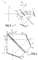
- FIG. 3 schematically illustrates by way of nonlimiting example, an application to the case of circular polarizations.
- the polarization separating surface SPa is formed by a cholesteric type liquid crystal cell; it is constituted in itself conventional, for example using two glass slides between which is contained the liquid crystal.
- the light propagates along the first optical axis 5 towards the polarization separating surface SPa which, in the nonlimiting example described, on the one hand transmits a polarized beam FC1 (symbolized by an arrow in dotted lines) comprising the left circular polarization PG; and, on the other hand, reflects a polarized beam FC2 having the right circular polarization PD.
- FC1 polarized beam
- FC2 polarized beam
- These two beams having the two complementary polarizations are then reflected by the first and second mirrors M1, M2 and both illuminate the spatial light modulator 12a.
- the latter is an LCD screen, the cells of which can be calculated (in itself traditional, in particular as regards the thickness and the refractive indices) so that, at rest, they reverse the direction of each circular polarization, for a length wave corresponding to that for which the separating surface SPa acts.
- the cells of the LCD screen 12a are activated, the birefringence disappears and the direction of rotation is preserved.
- FIG. 4 schematically shows by way of nonlimiting example, a compact structure and compatible with industrial production requirements, structure in which the elements cited in the preceding examples are contained with the exception of course of the light source and the projection screen.
- the projection device 1 comprises two symmetrical blocks 20, 21, of a transparent material (for example glass or molded plastic), arranged opposite and between which are interposed, on the one hand, the thin layers dielectrics which form the polarization separating surface SP, and on the other hand, the LCD screen 12.
- a transparent material for example glass or molded plastic
- Each glass block 20, 21 has a lens on one of these faces 23: the first block 20 carries the collimating lens LC and the second block 21 carries the projection lens LP.
- the assembly formed by the two blocks 20, 21 comprises, on the one hand opposite to the collimating lens LC, a first inclined face 24 (formed on the second block 21) metallized so as to constitute the first mirror M1; and on the other hand, opposite the projection lens LP, a second inclined face 25 (formed on the first block 20) metallized so as to constitute the second mirror M2.
- This arrangement makes it possible to constitute the first and the second optical axes 5,8.
- the light modulation assembly of the invention making it possible to superimpose the two complementary polarization beams as described with reference to FIGS. 1 to 5, is directly compatible for monochrome images, but it is also compatible with various known methods used for project color images.
- One of these methods may consist in providing the spatial light modulator 12 with a red, green or blue colored filter for each elementary image point: a group of three consecutive elementary points or pixels has the three colors.
- the coding of the video signal ensures the relative dosage of these three colors in each group of three pixels.
- a white light source and a CSP cube of the broadband type can be used for the separation of the complementary polarizations.
- the disadvantage of this technique is that it divides the resolution of the image by three, compared to monochrome operation.
- Another known method for forming a color image consists in using three optical valves, that is to say three LCD screens instead of one, and of superimposing the projected images.
- Each of the three LCD screens is illuminated by only one of the primary colors, blue, red and green. It is advantageous to have only one projection optic on the projection screen, in particular in order to be able to easily vary the magnification of the image.
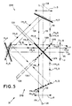
- FIG. 5 schematically shows a color projector 30 comprising at least two light modulation assemblies, EMB, EMR, which are nested so as to comprise two common axes.
- Each modulation set is associated with a light source SB, SR, the two sources producing a light of different color, for example blue for the first source SB associated with the first modulation set EMB, and red for the second source SR associated with the second EMR modulation package.
- Each modulation assembly is similar to that shown in FIGS. 1a, 1b and its elements have the same references followed by the letter B or R depending on whether they belong to the assembly assigned to blue light or to red light.
- the blue light produced by the blue source SB passes through a collimating lens LCB which makes it a beam FB, propagating on the first optical axis 5B in the direction of a polarization splitting surface SPB.
- the latter generates a first and a second polarized beams (blue in color) FP1B and FP2B which propagate respectively on the first optical axis 5B and on the second optical axis intended to form a projection axis 8 (these two axes forming an angle of 90 °), in the direction of the first and second mirrors M1B, M2B respectively.
- These two beams are reflected by the mirrors M1B, M2B and then propagate on the same third optical axis 13B (forming an angle of 45 ° with axes 5 and 8) with opposite directions, so as to illuminate the LCD screen 12B with two orthogonal and complementary polarizations of blue color; the LCD screen 12B being arranged on the third optical axis 13B. Having crossed the LCD screen 12B, these beams are modulated by the latter and constitute modulated beams FM1B, FM2B. These modulated beams are reflected by the mirrors M2B, M1B towards the separating surface SPB, from which they emerge as already represented in FIG.
- first and second optical axes 5,8 are common to the two modulation assemblies EMB and EMR, and that consequently the two light sources SB and SR are on a same first optical axis 5BR, opposite each other with respect to the projection axis 8. Consequently, the optical diagram concerning the beams formed from the red light produced by the source SR is symmetrical of that which has been described for blue light, with respect to the projection axis 8.
- the projection lens LP optically combines both the LCD screen 12B (blue light) with the projection screen 2 and the latter with the LCD screen 12R (red light) .
- the separating surfaces SPB and SPR are each made to act selectively, that is to say, to act only for light having the color to which they correspond.
- the separating surfaces SPB and SPR can be formed for this purpose by a stack of thin dielectric layers (not shown) deposited on a glass surface, in a manner in itself conventional when it is desired to constitute filters or prisms or mirrors selective acting on a given wavelength range.
- the mirrors M1B, M2B intended to reflect the blue light must allow the beams of red color to pass practically without loss, and likewise for the mirrors M1R, M2R which must reflect the beams of red light and let the blue light beams through. Consequently, the mirrors M1B, M2B and M1R, M2R to be reflective only for the color to which they correspond, can also be produced by a stack of thin dielectric layers deposited on a glass surface.
- the color projector of the invention may include at least one more light modulator assembly, assigned to the third primary color, green for example.
- This third set for green is not shown in FIG. 5, but it has in common with the two blue and red sets EMB, EMR its second optical axis, that is to say the projection axis 8.
- the three sets are deduced from each other by rotation around this projection axis, by an angle of 90 ° for example (or any angle such that the three LCD screens do not touch).
- the third set for the color green could be arranged in such a way that, its projection axis being coincident with the projection axis 8, its first optical axis (axis carrying the light source, the collimating lens, the separating surface and the first mirror) would be perpendicular to the plane of Figure 1.
- the modulation assemblies EMB, EMR are assembled in such a way that the projection objective LP is common to all these sets, whatever their number, and that the optical path distances between l projection lens LP and the various LCD screens 12B, 12R are equal.
- color projector 30 Another advantage of the color projector 30 is that, compared to the monochrome projector comprising a single LCD screen 12 described in FIG. 1, the minimum distance D provided by the triangular structure, between the projection lens and each LCD screen is kept. It is noted that it is also possible in a structure with several LCD screens to introduce field lenses as described in FIG. 2.
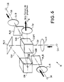
- Figure 6 is a perspective view which allows to better locate the elements of a color projector 30 of the type shown in Figure 5, and comprising three modulation sets each assigned to a different color, for example blue, red respectively and green B, R, V.
- the color projector 30 has a projection axis 8 common to the three colors, formed by the three second optical axes 8B, 8R, 8V. It comprises three polarization separating surfaces SPB, SPR, SPV (not shown in the figure) of the wavelength selective type, and according to a characteristic of the invention, these three separating surfaces are all contained in the same triple separator cube. polarization of CSPT. It also has three reflective surfaces of selective type in wavelength each forming a second mirror M2B, M2R, M2V, and according to a characteristic of the invention these three second mirrors are contained in the same mirror cube CM.
- a blue light source SB and a red light source SR are arranged on the same first optical axis 5BR, opposite each other relative to the projection axis 8.
- the triple polarization splitter cube CSPT and located at equal distance from the two sources SB, SR at the intersection of the projection axis 8 with the first optical axis 5BR.
- the mirror cube CM is arranged on the projection axis 8 opposite the projection lens LP with respect to the first optical axis 5BR.
- the mirror cube CM and the first mirror M1B for blue light are on the third optical axis 13B where only beams of blue light propagate in opposite directions, and on which must be located the spatial light modulator or LCD screen 12B (not represented).
- each color has its LCD screen 12 arranged on the third optical axis 13B, 13R, 13V of the corresponding modulation assembly. But for the sake of clarity in FIG. 5, the LCD screens 12 or optical valves are not shown. It should be specified that these LCD screens 12 are in a plane perpendicular to the third optical axis 13 which carries them and are in the same plane (not shown) as that which contains the corresponding separating surface SP (contained in the CSPT cube).
- the mirror cube CM and the first mirror M1R for the red light are on the third optical axis 13R.
- the green light source SV is located on its first optical axis 5V, which is perpendicular to both the first optical axis 5BR (blue and red colors) and to the projection axis 8, and which passes through the intersection of these two axes.
- An LCV collimator lens for green light is located on the optical axis SV, between the green source SV and the triple separator cube CSPT.
- a first mirror M1V for green light is located on the first optical axis 5V of green light; and this mirror determines with the mirror cube CM a third optical axis 13V for green light.
- the light sources SB, SR and SV are monochromatic. They are either primary sources, that is to say producing light themselves; or secondary sources and in this case the light can be white light produced by a single white primary source, associated with an element which allows the separation of the three primary colors: red, green, blue.
- Such a structure is in itself classic. Cubes (or prisms) of color separators known as dichroic cubes are commonly found in trade and it suffices to transmit (using optical fibers for example) each colored beam to the point where the sources SB are located, SR, SV (shown in Figures 5.6) of corresponding color.
- the polarization separating surfaces SPB, SPR, SPV and the surfaces which form the mirrors M1B, M2B, M1R, M2R, M1V, M2V must act selectively; on the other hand, the polarizing separating surfaces SPB, SPR, SPV on one side, and the second mirrors M2B, M2R, M2V on the other hand, must be nested, in planes which intersect.
- Figures 7a, 7b, 7c are perspective views which illustrate the nesting of these surfaces, taking for example a case where the polarization separating surfaces SPB, SPR, SPV, are contained in the same cube CSPT.
- Figure 7a shows the CSPT cube, the 12 edges of which are marked A1 to A12.
- One of the three polarization separating surfaces for example the separating surface SPV assigned to the green light, is formed in the plane containing the two opposite edges A2 and A7.
- FIG. 7b shows the CSPT cube and more particularly shows another polarization separating surface formed in the plane containing the two opposite edges A9 and A11; with reference to the example of FIG. 6, if the separating surface of FIG. 7a is the SPV surface, the surface shown in FIG. 7b is the separating surface SPB assigned to the blue light.
- FIG. 7c shows the cube CSPT and represents the separating surface SPR assigned to the red, separating surface which is formed in the plane containing the two opposite edges A10 and A12.
- Figures 7a to 7c show that the separating surfaces intersect and the example of these figures can also be applied to the case of selective reflective surfaces which must constitute the second mirrors M2B, M2R and M2V in the version shown in Figures 5 and 6 .
- such cubes can be constituted by an assembly of elementary parts, transparent to light, glass or plastic for example.
- FIGS. 8a, 8b, 8c show the same set of such elementary parts PE1 to PE8, the assembly of which leads to obtaining a cube such as the CSPT cube shown in FIGS. 7a to 7c, and which can contain three polarization separating surfaces.
- a cube such as the CSPT cube shown in FIGS. 7a to 7c
- FIGS. 8a to 8c can also apply to the production of a cube CM containing three selective mirrors.
- the elementary parts PE1 to PE8 have a pyramidal shape and have one or two of their treated faces, that is to say covered with stacks of thin layers. These elementary pieces form a cube when they are brought together.
- the elementary pieces PE1 to PE8 pyramidal correspond to pieces which would be obtained by cutting a cube, along the three planes each containing a separating surface SPV, SPB, SPR shown in FIGS. 7a, 7b, 7c.
- the eight elementary parts PE1 to PE8 are then obtained; it is observed that parts are identical two by two: the first and the eighth parts PE1, PE8; the second and seventh parts PE2, PE7; the fourth and fifth pieces PE4, PE5; the third and sixth parts PE3, PE6.
- pyramidal parts of shapes different from those of parts Pe1 to Pe8 shown in FIGS. 8a to 8c can also be obtained by cutting a cube along only two planes each containing either a separating surface SPR, SPB, or a second mirror M2R, M2B, following the example shown in Figure 5.
- FIGS. 8a and 8c illustrate by hatching the treatments or stacks of thin dielectric layers produced on one or two faces of some of the elementary parts, with a view to constituting mirrors or polarization separators, acting selectively.
- FIG. 8a illustrates by inclined hatching a first type of stacking of thin layers dielectric CM1 (acting for example for green light) produced on one side of the elementary parts PE2, PE4, PE6 and PE8.
- FIG. 8b shows by horizontal hatching a second stack of thin dielectric layers CM2 (acting for example for red light) produced on one face of the four parts PE3, PE4, P7 and PE8.
- FIG. 8c shows by vertical hatching a third type of stack CM3 of thin dielectric layers (acting by blue light) produced on one face of the four parts PE1, PE2, PE3 and PE4.
- the second mirrors (M2) nested between them can be obtained by the same technique as the cube with three polarization separating surfaces (assembly of elementary pyramids), using the same thin film deposition technology of materials dielectric, with the difference that the functions obtained (mirror) are selective in wavelength and insensitive to polarizations.
Landscapes
- Physics & Mathematics (AREA)
- General Physics & Mathematics (AREA)
- Optics & Photonics (AREA)
- Engineering & Computer Science (AREA)
- Multimedia (AREA)
- Signal Processing (AREA)
- Liquid Crystal (AREA)
- Projection Apparatus (AREA)
Claims (20)
- Bildprojektor mit wenigstens zwei Lichtmodulationseinheiten (EMR, EMB, EMV), entweder einer allen Lichtmodulationseinheiten gemeinsamen Lichtquelle oder Lichtquellen (SR, SB, SV), die jeweils einer der Lichtmodulationseinheiten zugeordnet sind, und einem Projektionsobjektiv (LP), wobei jede Lichtmodulationseinheit einen Raumlichtmodulator (12R; 12B; 12V), der selektiv auf die Polarisation des Lichtes einwirkt, das er empfängt, einen Polarisationsseparator (SPR; SPB; SPV), der das Licht von der gemeinsamen Lichtquelle oder der der betreffenden Modulationseinheit zugeordneten Lichtquelle in Abhängigkeit von seiner Polarisation in ein erstes polarisiertes Strahlenbündel und ein zweites polarisiertes Strahlenbündel unterschiedlicher Ausbreitungsrichtung und unterschiedlicher sowie komplementärer Polarisation trennt, und Mittel (M1R; M1B; M1V) enthält, um das erste polarisierte Strahlenbündel und das zweite polarisierte Strahlenbündel auf einer gleichen optischen Achse (13R; 13B; 13V) mit entgegengesetzten Ausbreitungsrichtungen zu überlagern, wobei der Raumlichtmodulator auf der optischen Achse angeordnet ist, um das erste polarisierte Strahlenbündel und das zweite polarisierte Strahlenbündel zu modulieren, die aus dem Raummodulator austreten und ein erstes bzw. ein zweites moduliertes Strahlenbündel komplementärer Polarisation bilden, und wobei die beiden modulierten Strahlenbündel wieder durch den gleichen Polarisationsseparator hindurchtreten, durch den sie auf einer gleichen Achse (8; 5B; 5R; 5V) und mit einer gleichen Richtung überlagert und je nach deren Modulation durch den Raumlichtmodulator auf das Projektionsobjektiv (LP) und/oder auf die Lichtquelle gerichtet werden, dadurch gekennzeichnet, daß die Polarisationsseparatoren (SPR, SPB, SPV) wellenlängenselektiv sind, um selektiv auf eine Farbe einzuwirken und verschachtelte sowie gekreuzte Flächen zu bilden.
- Bildprojektor nach Anspruch 1, dadurch gekennzeichnet, daß die Polarisationsseparatoren von dem Typ sind, der durch einen Stapel aus dünnen dielektrischen Schichten gebildet ist.
- Bildprojektor nach einem der vorhergehenden Ansprüche, dadurch gekennzeichnet, daß in jeder Modulationseinheit (EMR; EMB; EMV) der Polarisationsseparator (SPR; SPB; SPV) und der Raumlichtmodulator (12R; 12B; 12V) in einer gleichen Ebene angeordnet sind.
- Bildprojektor nach einem der vorhergehenden Ansprüche, dadurch gekennzeichnet, daß jede Modulationseinheit (EMR; EMB; EMV) einen ersten und einen zweiten Spiegel (M1R, M2R; M1B, M2B) enthält, die auf einer gleichen optischen Achse (13R; 13B) wie der Raumlichtmodulator beiderseits dieses letzteren angeordnet sind, wobei jeder Spiegel einerseits ein polarisiertes Strahlenbündel mit einer gegebenen Polarisationsrichtung (P1) zu dem Raummodulator und andererseits ein moduliertes Strahlenbündel mit einer zur ersten komplementären Polarisationsrichtung zu dem Polarisationsseparator (SPR, SPB, SPV) reflektiert.
- Bildprojektor nach Anspruch 4, dadurch gekennzeichnet, daß in jeder Modulationseinheit (EMR; EMB; EMV) der Polarisationsseparator (SPR; SPB; SPV) und die beiden Spiegel einen Lichtpfad definieren, der den Strahlenbündeln der beiden komplementären Polarisationen gemeinsam ist.
- Bildprojektor nach Anspruch 5, dadurch gekennzeichnet, daß der Lichtpfad eine dreieckige Form besitzt und daß die Strahlenbündel wieder durch den Polarisationsseparator (SPR, SPB, SPV) hindurchtreten, um auf einer ersten oder einer zweiten Achse (8B; 5B) und mit einer gleichen Richtung überlagert zu werden.
- Projektor nach einem der vorhergehenden Ansprüche, dadurch gekennzeichnet, daß in jeder Modulationseinheit (EMR; EMB; EMV) der polarisationsseparator (SPR; SPB; SPV) eine Fläche besitzt, die wesentlich kleiner als die des Raummodulators ist.
- Projektor nach einem der vorhergehenden Ansprüche, dadurch gekennzeichnet, daß der Polarisationsseparator (38) von dem Typ ist, der für die linearen Polarisationen wirkt.
- Projektor nach einem der vorhergehenden Ansprüche, dadurch gekennzeichnet, daß er wenigstens drei Modulationseinheiten (EMB, EMR, EMV) enthält, die jeweils dafür bestimmt sind, eine unterschiedliche Farbe (R, V, B) zu verarbeiten und die eine gemeinsame optische Achse (8) besitzen.
- Projektor nach Anspruch 9, dadurch gekennzeichnet, daß zwei der Modulationseinheiten (EMB, EMR, EMV) zwei gemeinsame optische Achsen (5, 8) enthalten.
- Projektor nach Anspruch 9, dadurch gekennzeichnet, daß die gemeinsame optische Achse (8) eine Projektionsachse ist, die das den drei Farben (R, V, B) gemeinsame Projektionsobjektiv (LP) enthält.
- Projektor nach Anspruch 10, dadurch gekennzeichnet, daß die drei Polarisationsseparatoren (SPR, SPB, SPV), die drei ersten Spiegel und die drei zweiten Spiegel wellenlängenselektiv sind.
- Projektor nach Anspruch 12, dadurch gekennzeichnet, daß die drei Polarisationsseparatoren (SPR, SPB, SPV) jeweils eine Trennfläche enthalten, wobei die Polarisationsseparatoren von dem Typ sind, der durch einen Stapel aus dünnen dielektrischen Schichten gebildet ist, und wobei die Trennflächen verschachtelt sind.
- Projektor nach Anspruch 13, dadurch gekennzeichnet, daß die drei Polarisationsseparatoren (SPR, SPB, SPV) in einem gleichen, transparenten Kubus (CSPT) gebildet sind, der selbst durch die Vereinigung von Elementarpyramiden (PE1-PE8) gebildet ist, die Stücken gleichen, die durch Zerschneiden des transparenten Kubus entlang unterschiedlicher, jeweils einer Trennfläche entsprechender Ebenen erhalten werden.
- Projektor nach Anspruch 14, dadurch gekennzeichnet, daß jede Polarisationstrennfläche durch Teilflächen gebildet ist, die jeweils auf einer Seite einer Elementarpyramide (PE1-PE8) gebildet sind, auf welcher Seite ein Stapel von dünnen, dielektrischen aktiven Schichten für einen gegebenen Wellenlängenbereich verwirklicht ist.
- Projektor nach Anspruch 12, dadurch gekennzeichnet, daß die drei zweiten Spiegel jeweils von dem Typ sind, der durch einen Stapel von dünnen dielektrischen Schichten gebildet ist, und verschachtelt sind.
- Projektor nach Anspruch 16, dadurch gekennzeichnet, daß die zweiten Spiegel in einem gleichen transparenten Kubus (CM) gebildet sind, der selbst durch die Vereinigung von Elementarpyramiden (PE1-PE8) gebildet ist, die Stücken gleichen, die durch Zerschneiden des transparenten Kubus (CM) entlang der unterschiedlichen, jeweils einem zweiten Spiegel entsprechenden Ebenen erhalten werden.
- Projektor nach Anspruch 17, dadurch gekennzeichnet, daß jeder Spiegel durch Teilflächen gebildet ist, die jeweils auf einer Seite einer Elementarpyramide (PE1-PE8) gebildet sind, auf welcher Seite ein Stapel von dünnen, dielektrischen aktiven Schichten für einen vorgegebenen Wellenlängenbereich verwirklicht ist.
- Projektor nach einem der vorhergehenden Ansprüche, dadurch gekennzeichnet, daß er wenigstens drei Modulationseinheiten (EMR, EMB, EMV) enthält, die jeweils für eine unterschiedliche Farbe bestimmt sind, wobei eine einzige Lichtquelle ein Weißlichtstrahlenbündel liefert, ein erster dichroitischer Kubus das Weißlicht in drei unterschiedliche Farben trennt und jedes Licht einer gegebenen Farbe zu dem Polarisationsseparator (SPR, SPB, SPV) der entsprechenden Modulationseinheit reflektiert wird, und daß ein zweiter dichroitischer Kubus die von jeder der Modulationseinheiten (EMR, EMB, EMV) zurückkommenden Lichtanteile überlagert, um ein polychromatisches Strahlenbündel zu bilden, das sich in Richtung des Projektionsobjektivs (LP) ausbreitet.
- Projektor nach Anspruch 19, dadurch gekennzeichnet, daß die Modulationseinheiten (EMR, EMB, EMV) jeweils durch zwei transparente Blöcke gebildet sind, die durch eine Ebene getrennt sind, die einen Polarisationsseparator (SP) und einen Raummodulator (12B, 12R, 12V) enthält, und daß die beiden dichroitischen Kuben übereinanderliegen und auf drei Seiten von den drei Modulationseinheiten (EM1, EM2, EM3) umgeben sind, wobei jede Modulationseinheit einen Beleuchtungsspiegel enthält, der gegenüber einer Seite des ersten dichroitischen Kubus angeordnet ist.
Applications Claiming Priority (2)
| Application Number | Priority Date | Filing Date | Title |
|---|---|---|---|
| FR9010251A FR2665773B1 (fr) | 1990-08-10 | 1990-08-10 | Dispositif de projection d'images utilisant deux composantes orthogonales de polarisation de la lumiere. |
| FR9010251 | 1990-08-10 |
Publications (2)
| Publication Number | Publication Date |
|---|---|
| EP0475796A1 EP0475796A1 (de) | 1992-03-18 |
| EP0475796B1 true EP0475796B1 (de) | 1995-06-21 |
Family
ID=9399609
Family Applications (1)
| Application Number | Title | Priority Date | Filing Date |
|---|---|---|---|
| EP91402173A Expired - Lifetime EP0475796B1 (de) | 1990-08-10 | 1991-08-02 | Bildprojektionssystem mit Verwendung von zwei orthogonalen Lichtpolarizationskomponenten |
Country Status (5)
| Country | Link |
|---|---|
| US (1) | US5181054A (de) |
| EP (1) | EP0475796B1 (de) |
| JP (1) | JP3149469B2 (de) |
| DE (1) | DE69110585T2 (de) |
| FR (1) | FR2665773B1 (de) |
Families Citing this family (43)
| Publication number | Priority date | Publication date | Assignee | Title |
|---|---|---|---|---|
| JP2942344B2 (ja) * | 1989-11-22 | 1999-08-30 | 旭光学工業株式会社 | プロジェクター |
| FR2669744B1 (fr) * | 1990-11-23 | 1994-03-25 | Thomson Csf | Dispositif d'eclairage et application a un dispositif de visualisation. |
| FR2680882B1 (fr) * | 1991-08-06 | 1993-10-29 | Thomson Csf | Projecteur d'images a efficacite lumineuse orptimisee. |
| WO1993024857A1 (en) * | 1992-06-01 | 1993-12-09 | Bell Communications Research, Inc. | Polarization-independent display system |
| FR2696246B1 (fr) * | 1992-09-28 | 1994-11-04 | Sextant Avionique | Procédé et dispositif de projection d'une image en couleur résultant d'une modulation par valves optiques. |
| US5398081A (en) * | 1993-06-07 | 1995-03-14 | Raychem Corporation | Apparatus for projecting colored images |
| FR2707447B1 (fr) * | 1993-07-09 | 1995-09-01 | Thomson Csf | Dispositif de visualisation couleurs. |
| FR2711878B1 (fr) * | 1993-10-29 | 1995-12-15 | Thomson Csf | Dispositif de visualisation couleurs et procédé de réalisation. |
| US5428469A (en) * | 1993-11-16 | 1995-06-27 | Minnesota Mining And Manufacturing Company | Liquid crystal display projection systems employing polarizing beam splitters and passing light through display cell from both directions |
| KR100330109B1 (ko) * | 1994-06-17 | 2002-11-22 | 똥송 쎄에스에프 | 광학필터링장치및액정프로젝터 |
| FR2722319B1 (fr) * | 1994-07-08 | 1996-08-14 | Thomson Csf | Dispositif de visualisation couleurs |
| US5748164A (en) * | 1994-12-22 | 1998-05-05 | Displaytech, Inc. | Active matrix liquid crystal image generator |
| WO1996020422A1 (en) | 1994-12-28 | 1996-07-04 | Seiko Epson Corporation | Polarized lighting apparatus and projection type display device |
| FR2732783B1 (fr) * | 1995-04-07 | 1997-05-16 | Thomson Csf | Dispositif compact de retroprojection |
| US5757547A (en) * | 1995-04-24 | 1998-05-26 | Polycom, Inc. | High efficiency homogeneous polarization converter |
| IL113796A0 (en) * | 1995-05-19 | 1995-08-31 | Unic View Ltd | Projector |
| WO1998007279A1 (en) * | 1996-08-12 | 1998-02-19 | National Research Council Of Canada | High efficiency projection displays having thin film polarizing beam-splitters |
| FR2738645B1 (fr) | 1995-09-12 | 1997-10-03 | Thomson Csf | Systeme d'illumination d'un ecran de visualisation couleurs electrooptique |
| EP0880725A4 (de) * | 1995-10-13 | 2000-01-05 | Unic View Ltd | Projektor |
| US5995284A (en) * | 1996-03-29 | 1999-11-30 | 3M Innovative Properties Company | Polarized illumination system for LCD projector |
| FR2751398B1 (fr) * | 1996-07-16 | 1998-08-28 | Thomson Csf | Dispositif d'eclairage et application a l'eclairage d'un ecran transmissif |
| US5982541A (en) * | 1996-08-12 | 1999-11-09 | Nationsl Research Council Of Canada | High efficiency projection displays having thin film polarizing beam-splitters |
| FR2755516B1 (fr) | 1996-11-05 | 1999-01-22 | Thomson Csf | Dispositif compact d'illumination |
| FR2755530B1 (fr) * | 1996-11-05 | 1999-01-22 | Thomson Csf | Dispositif de visualisation et ecran plat de television utilisant ce dispositif |
| US5943168A (en) * | 1997-09-11 | 1999-08-24 | Hughes-Jvc Technology Corporation | Sawtooth interleave polarization combiner |
| US6046858A (en) * | 1997-10-16 | 2000-04-04 | Aurora Systems, Inc. | Light separation and recombination system for an off-axis projector |
| JP3959878B2 (ja) * | 1998-04-08 | 2007-08-15 | セイコーエプソン株式会社 | 光選択プリズムの製造方法 |
| US20020176054A1 (en) * | 1999-12-30 | 2002-11-28 | Mihalakis George M. | Reflective liquid-crystal-on-silicon projection engine architecture |
| US6375330B1 (en) | 1999-12-30 | 2002-04-23 | Gain Micro-Optics, Inc. | Reflective liquid-crystal-on-silicon projection engine architecture |
| FR2819061B1 (fr) * | 2000-12-28 | 2003-04-11 | Thomson Csf | Dispositif de controle de polarisation dans une liaison optique |
| JP2005518562A (ja) * | 2002-02-19 | 2005-06-23 | ユナキス・バルツェルス・アクチェンゲゼルシャフト | 狭帯域光源を用いて画像を投影するためのシステム |
| DE10361943A1 (de) * | 2003-12-24 | 2005-07-21 | Carl Zeiss | Optischer SChalter |
| WO2005114987A1 (de) * | 2004-05-22 | 2005-12-01 | Diehl Bgt Defence Gmbh & Co. Kg | Vorrichtung zur erfassung einer objektszene |
| US7320521B2 (en) * | 2004-07-12 | 2008-01-22 | Next Wave Optics, Inc. | Optical engine architectures |
| DE102004050165B4 (de) * | 2004-10-14 | 2006-11-02 | Hensoldt Ag | Optisches Beobachtungsgerät mit einer Vorrichtung zum Schutz gegen einfallende Störstrahlung |
| US7530693B2 (en) * | 2005-05-31 | 2009-05-12 | Next Wave Optics Inc. | Single MEMS imager optical engine |
| GB0514656D0 (en) * | 2005-07-16 | 2005-08-24 | Cairn Res Ltd | Control of illumination in microscopy |
| DE102008054443A1 (de) | 2008-01-16 | 2009-07-23 | Robert Bosch Gmbh | Anzeigevorrichtung für ein Kfz sowie Verfahren für die Darstellung eines Bildes |
| DE102013113807A1 (de) * | 2013-12-11 | 2015-06-11 | Hella Kgaa Hueck & Co. | Beleuchtungseinrichtung für ein Kraftfahrzeug |
| DE102017109679A1 (de) | 2017-05-05 | 2018-11-08 | Jos. Schneider Optische Werke Gmbh | Vorrichtung und Verfahren zum Erzeugen einer Ausgangslichtemission und Scheinwerfer |
| CN110376669A (zh) * | 2018-04-13 | 2019-10-25 | 甘肃智呈网络科技有限公司 | 一种立方分光棱镜 |
| DE102018110117A1 (de) * | 2018-04-26 | 2019-10-31 | Carl Zeiss Microscopy Gmbh | Optikanordnung und Verfahren zur Lichtstrahlformung für ein Lichtmikroskop |
| CN114815236A (zh) * | 2021-01-27 | 2022-07-29 | 怡利电子工业股份有限公司 | 对称光路3d抬头显示器 |
Family Cites Families (10)
| Publication number | Priority date | Publication date | Assignee | Title |
|---|---|---|---|---|
| US2449287A (en) * | 1946-09-23 | 1948-09-14 | Merrill M Flood | Polarizing beam-splitting prism |
| EP0083090B1 (de) * | 1981-12-28 | 1987-09-09 | Hughes Aircraft Company | Hocheffizientes optisches System für dreifarbige Bildprojektion durch Lichtventile aus flüssigem Kristall mit farbselektiver Verpolarisation |
| US5075798A (en) * | 1984-10-22 | 1991-12-24 | Seiko Epson Corporation | Projection-type display device |
| GB2201808B (en) * | 1987-02-25 | 1990-12-05 | Rolls Royce Plc | Identification in manufacture |
| DE3720375A1 (de) * | 1987-06-19 | 1988-12-29 | Fraunhofer Ges Forschung | Projektionsvorrichtung |
| US5097323A (en) * | 1988-01-25 | 1992-03-17 | Casio Computer Co., Ltd. | Liquid crystal projector |
| NL8802104A (nl) * | 1988-08-26 | 1990-03-16 | Philips Nv | Beeldprojektie-inrichting. |
| NL8802513A (nl) * | 1988-10-13 | 1990-05-01 | Philips Nv | Projektiesysteem voor een kleurenprojektietelevisie, kleurenrekombinatiestelsel en kleurenselektiestelsel voor toepassing in een dergelijk projektiesysteem. |
| US5042921A (en) * | 1988-10-25 | 1991-08-27 | Casio Computer Co., Ltd. | Liquid crystal display apparatus |
| JPH02120421U (de) * | 1989-03-13 | 1990-09-28 |
-
1990
- 1990-08-10 FR FR9010251A patent/FR2665773B1/fr not_active Expired - Fee Related
-
1991
- 1991-08-02 DE DE69110585T patent/DE69110585T2/de not_active Expired - Fee Related
- 1991-08-02 US US07/739,488 patent/US5181054A/en not_active Expired - Fee Related
- 1991-08-02 EP EP91402173A patent/EP0475796B1/de not_active Expired - Lifetime
- 1991-08-09 JP JP22358391A patent/JP3149469B2/ja not_active Expired - Fee Related
Also Published As
| Publication number | Publication date |
|---|---|
| DE69110585D1 (de) | 1995-07-27 |
| JP3149469B2 (ja) | 2001-03-26 |
| FR2665773A1 (fr) | 1992-02-14 |
| EP0475796A1 (de) | 1992-03-18 |
| FR2665773B1 (fr) | 1993-08-20 |
| JPH05150207A (ja) | 1993-06-18 |
| DE69110585T2 (de) | 1995-12-21 |
| US5181054A (en) | 1993-01-19 |
Similar Documents
| Publication | Publication Date | Title |
|---|---|---|
| EP0475796B1 (de) | Bildprojektionssystem mit Verwendung von zwei orthogonalen Lichtpolarizationskomponenten | |
| EP0527084B1 (de) | Bildprojektor mit optimierter Lichtausbeute | |
| EP0451034B1 (de) | Vorrichtung für Bildprojektion | |
| EP0512099B1 (de) | Bilddarstellungsgerät | |
| EP0485268B1 (de) | Matrix-Bildprojektor mit zwei polarisierten Strahlen | |
| EP0633702B1 (de) | Farbanzeigegerät | |
| EP0547949B1 (de) | Optischer Polarisationsstrahlenteiler und seine Verwendung in einem Abbildungssystem | |
| EP0383646B1 (de) | Hochauflösende Farbsichtanzeigevorrichtung | |
| WO1998020390A1 (fr) | Dispositif de visualisation et ecran plat de television utilisant ce dispositif | |
| EP0572292B1 (de) | Farbstrahlteiler und Abbildungsprojektor der diesen benutzt | |
| EP0740477B1 (de) | Vorrichtung zur Polarisationstrennung und Anwendung für ein Beleuchtungssystem eines Flüssigkristallschirms | |
| EP0736795B1 (de) | Kompakte Vorrichtung für Retroprojektion | |
| EP0740476B1 (de) | Vorrichtung zur Polarisationstrennung und Anwendung in einem Beleuchtungssystem einer Flüssigkristallanzeigevorrichtung | |
| EP0757274A1 (de) | Optische Polarisationsvorrichtung und Flüssigkristall-Projektionssystem damit | |
| EP0478425B1 (de) | Vorrichtung zur Erzeugung von mehreren Lichtstrahlen | |
| FR2693004A1 (fr) | Dispositif de collimation de faible encombrement, en particulier pour visuel de casque. | |
| FR2647902A1 (fr) | Dispositif interferometrique, notamment pour spectro-imageur par transformee de fourier multiplex a defilement, et spectro-imageur le comportant | |
| EP0729279A2 (de) | Monolichtventil-Farbprojektionsysteme | |
| FR2658925A1 (fr) | Dispositif d'eclairage en lumiere polarisee et materiel de visualisation comportant au moins un tel dispositif. | |
| EP3017333A1 (de) | Head-up-anzeige | |
| BE513643A (de) | ||
| WO2016162632A1 (fr) | Système d'affichage d'une image flottante |
Legal Events
| Date | Code | Title | Description |
|---|---|---|---|
| PUAI | Public reference made under article 153(3) epc to a published international application that has entered the european phase |
Free format text: ORIGINAL CODE: 0009012 |
|
| AK | Designated contracting states |
Kind code of ref document: A1 Designated state(s): DE GB NL |
|
| 17P | Request for examination filed |
Effective date: 19920402 |
|
| 17Q | First examination report despatched |
Effective date: 19931206 |
|
| RAP1 | Party data changed (applicant data changed or rights of an application transferred) |
Owner name: THOMSON-CSF |
|
| GRAA | (expected) grant |
Free format text: ORIGINAL CODE: 0009210 |
|
| AK | Designated contracting states |
Kind code of ref document: B1 Designated state(s): DE GB NL |
|
| REF | Corresponds to: |
Ref document number: 69110585 Country of ref document: DE Date of ref document: 19950727 |
|
| GBT | Gb: translation of ep patent filed (gb section 77(6)(a)/1977) |
Effective date: 19950821 |
|
| PLBE | No opposition filed within time limit |
Free format text: ORIGINAL CODE: 0009261 |
|
| STAA | Information on the status of an ep patent application or granted ep patent |
Free format text: STATUS: NO OPPOSITION FILED WITHIN TIME LIMIT |
|
| 26N | No opposition filed | ||
| REG | Reference to a national code |
Ref country code: GB Ref legal event code: IF02 |
|
| PGFP | Annual fee paid to national office [announced via postgrant information from national office to epo] |
Ref country code: GB Payment date: 20030616 Year of fee payment: 13 |
|
| PGFP | Annual fee paid to national office [announced via postgrant information from national office to epo] |
Ref country code: DE Payment date: 20030724 Year of fee payment: 13 |
|
| PGFP | Annual fee paid to national office [announced via postgrant information from national office to epo] |
Ref country code: NL Payment date: 20030828 Year of fee payment: 13 |
|
| PG25 | Lapsed in a contracting state [announced via postgrant information from national office to epo] |
Ref country code: GB Free format text: LAPSE BECAUSE OF NON-PAYMENT OF DUE FEES Effective date: 20040802 |
|
| PG25 | Lapsed in a contracting state [announced via postgrant information from national office to epo] |
Ref country code: NL Free format text: LAPSE BECAUSE OF NON-PAYMENT OF DUE FEES Effective date: 20050301 Ref country code: DE Free format text: LAPSE BECAUSE OF NON-PAYMENT OF DUE FEES Effective date: 20050301 |
|
| GBPC | Gb: european patent ceased through non-payment of renewal fee |
Effective date: 20040802 |
|
| NLV4 | Nl: lapsed or anulled due to non-payment of the annual fee |
Effective date: 20050301 |