EP0478486A2 - Kommunikationsverfahren und -anordnung in einer Schichtarchitektur - Google Patents
Kommunikationsverfahren und -anordnung in einer Schichtarchitektur Download PDFInfo
- Publication number
- EP0478486A2 EP0478486A2 EP91480131A EP91480131A EP0478486A2 EP 0478486 A2 EP0478486 A2 EP 0478486A2 EP 91480131 A EP91480131 A EP 91480131A EP 91480131 A EP91480131 A EP 91480131A EP 0478486 A2 EP0478486 A2 EP 0478486A2
- Authority
- EP
- European Patent Office
- Prior art keywords
- layer
- entity
- block
- entities
- access point
- Prior art date
- Legal status (The legal status is an assumption and is not a legal conclusion. Google has not performed a legal analysis and makes no representation as to the accuracy of the status listed.)
- Withdrawn
Links
- 238000004891 communication Methods 0.000 title claims abstract description 45
- 238000000034 method Methods 0.000 title claims abstract description 36
- 230000006870 function Effects 0.000 claims abstract description 47
- 230000008569 process Effects 0.000 claims description 19
- 230000004044 response Effects 0.000 claims description 9
- 230000004913 activation Effects 0.000 claims description 8
- 230000003213 activating effect Effects 0.000 claims 3
- 238000007726 management method Methods 0.000 description 8
- 238000001994 activation Methods 0.000 description 6
- 238000012545 processing Methods 0.000 description 6
- 230000000694 effects Effects 0.000 description 3
- 230000005540 biological transmission Effects 0.000 description 2
- 230000011664 signaling Effects 0.000 description 2
- 238000013459 approach Methods 0.000 description 1
- 238000012937 correction Methods 0.000 description 1
- 238000001514 detection method Methods 0.000 description 1
- 238000009432 framing Methods 0.000 description 1
- 230000010365 information processing Effects 0.000 description 1
- 230000000977 initiatory effect Effects 0.000 description 1
- 238000013507 mapping Methods 0.000 description 1
- 238000011084 recovery Methods 0.000 description 1
- 238000012546 transfer Methods 0.000 description 1
- 230000009466 transformation Effects 0.000 description 1
Images


Classifications
-
- H—ELECTRICITY
- H04—ELECTRIC COMMUNICATION TECHNIQUE
- H04L—TRANSMISSION OF DIGITAL INFORMATION, e.g. TELEGRAPHIC COMMUNICATION
- H04L9/00—Cryptographic mechanisms or cryptographic arrangements for secret or secure communications; Network security protocols
- H04L9/40—Network security protocols
Definitions
- the invention relates to the field of data communications in general and, in particular, to enhancements communications in layered protocol architectures, such as the Open System Interconnection (OSI) standard, for communication between data processing or end points and between layers within a node.
- OSI Open System Interconnection
- the Open Systems Interconnection (OSI) standard is one such layered architecture.
- a description of the OSI model is set forth in ISO International Standard 7498, Information Processing Systems - Open Systems Interconnection - Basic Reference Model, First Edition - 1984-10-15.
- OSI Service Access Point
- OSI refers to the things in a layer receiving service or giving service as entities.
- An entity may be a single process, a group of logically related processes, etc. We will adopt this term here as it is used in OSI.
- a provider entity in layer n may be attached to one or more SAPs which are attached to the same or different n+1 layer user entities.
- the provider in a given layer may route incoming blocks of information from lower layers to an appropriate entity in the next higher layer for which the information blocks are intended.
- PIBs protocol information blocks
- the term "protocol" indicates that such a block is received over a communications medium.
- PIBs may be further classified as protocol control blocks (PCBs) and protocol data blocks (PDBs).
- PCBs protocol control blocks
- PDBs contain the transport data that is to be delivered to a data using entity.
- PCBs contain control information, such as information used for the setup and teardown of a connection.
- the routing of PIBs between layers is accomplished by means of a SAP identification (SAP.ID) included in each PIB header.
- SAP.ID SAP identification
- a PIB is sent to the identified SAP.ID and thus to the next layer entity which is also attached to the SAP. Therefore, an entity in layer n is able to route PIBs to layer n+1 entities based on the SAP.ID contained in each PIB.
- the server entity is unable to distinguish and route PIBs based on their type (e.g., PCBs or PDBs).
- a final user entity must have the functionality to process both PCBs (connection establishment, XID exchanges, error blocks, etc,) and PDBs.
- XID stands for Exchange Identification.
- XID exchanges are defined as part of the System Network Architecture (SNA) standards, as well as by the OSI and other protocol standards. The purpose of an XID exchange, among other things, is initially to identify the end points and the parameters to be used in subsequent communication over a connection. The requirement that a final user entity have the capability to deal with all types of PIB exchanges that might occur on a given data connection is inefficient and inflexible for many environments.
- the invention solves this problem in a way that still conforms to the OSI standard, as an example, and in so doing offers a more powerful and flexible layered communications environment.
- our service access points are different from those defined by OSI, for example, we will refer to them merely as access points (APs).
- APs access points
- this logical grouping allows for the routing of PIBs or other messages derived from PIBs from a lower layer to the adjacent upper layer based both on logical group and PIB type.
- the entities in the upper layer that are within one logical group may include separate entities for control and management functions and separate entities for data transport purposes.
- a single smart PCB entity, for example, in an upper layer could service XID type PCBs for different data user entities.
- One data user entity might process OSI data, while another might process SNA data, and so on.
- provider entities in layer n may be attached to PIB APs for the routing of PIBs to entities in the adjacent upper layer n+1.
- the layer n+1 entities may be logically grouped for the purpose of routing PIBs from layer n to individual entities in layer n+1 within a group based on the type of information contained in the PIBs.
- a plurality of PIB APs are activated between an entity in layer n and a plurality of entities in layer n+1.
- a group classification is assigned to each AP at the time of activation. Each unique group classification forms a logical grouping of layer n+1 entities.
- the type of PIB that is processed by the layer n+1 entity associated with each AP is identified at the time of activation.
- the logical group for which the PIB is intended and the type of information contained in the PIB is determined from the PIB.
- the PIB is then routed to the particular AP associated with a layer n+1 entity that belongs to the identified logical group and which processes the identified PIB type.
- the PIB types are divided into protocol control blocks ( PCBs) and protocol data blocks (PDBs).
- PCBs may be used for controlling the setup and teardown of communication sessions between this system and remote systems and for other types of control functions. Therefore, PCBs are routed to a layer n+1 entity that performs control functions and PDBs are routed to a layer n+1 entity that provides data transport functions.
- activation of an AP is accomplished by sending a group activate message to each layer n+1 entity that is to be a member of a logical group. In response to the receipt of each group activate message, an activate AP message is generated which includes an identification of the AP and an indication of the function performed by the layer n+1 entity generating the message.
- the activate AP message is sent to the appropriate entity in layer n.
- the layer n entity is linked to the AP and a confirm message is sent to the layer n+1 entity that generated the activate AP message, thereby linking the layer n and the layer n+1 entities via the AP.
- An indication of the logical group to which a layer n+1 entity is to belong is included in each activate AP message.
- An AP control block is created in memory in response to each activate AP message by the layer n entity.
- the AP identification (AP.ID), group and layer n+1 entity type sending the activate AP message is stored in the AP control block.
- all AP control blocks in memory that belong to the group are linked together in some appropriate manner. In the preferred embodiment, this is done by storing cross referencing pointers in each of the AP control blocks in a group to the other AP control blocks in the group.
- all PIBs incoming to layer n contain a SAP
- this access point identification is selected always to be a predefined one of the layer n+1 entities in a group. In the preferred embodiment, this predefined access point is the one associated with the data user entity, i.e. the entity provided to process raw transport data, in layer n+1.
- the OSI model is shown in FIG. 1.
- the communication between one application such as a software module or device, 100, and another module or device 102 over a communication medium such as the cable 104 is described on the basis of seven layers, each of which performs certain functions within the communication protocol.
- the lowest layer is the physical layer 106.
- the physical layer 106 involves the actual connections and the signalling to the communication medium 104.
- the next layer up is the data link layer 108.
- This is the layer in which the physical delivery of raw data between nodes on the network is accomplished.
- the physical signaling protocol including link information, synchronization information, error correction information, PIB sizes, framing, etc. are conducted at this layer. In most networks, fundamental communication errors are detected and corrected here by retransmission or other means. Communication between a pair of nodes on the network depends on compatible implementation of data link layers.
- the link layer establishes, maintains and releases data links and is used for error detection and physical flow control.
- the third layer is the network layer 110.
- This layer controls the routing of information through the network, including addressing, network initialization, and the switching, segmenting and formatting of the information. Sometimes acknowledgement of raw delivery data is accomplished at the network layer, and sometimes it is accomplished at the data link layer.
- the next layer is the transport layer 112.
- This layer controls transparent data transfer, end-to-end control, multiplexing, mapping and the like.
- Data delivery may imply reliable delivery, as opposed to a best effort to deliver the data which must be accounted for in the layers below the transport layer.
- Other classes of reliability may be selected as options as well. For example, at the transport layer, for reliability class 0, it is assumed that the data has been communicated in a reliable manner, and such things as the retransmission of missing data, reordering of the data delivered out of order, recovery from transmission errors, etc. has been corrected at or below the transport layer.
- the fifth layer is the session layer 114.
- the session layer 114 utilizes the information from the transport layer to group pieces of data as associated with a given activity referred to as a session. Sessions occur between two entities at various locations on the network. At a given time, single nodes on the network may be involved in multiple sessions going to a plurality of other nodes, and many sessions may be multiplexed over the same network. However, the session layer services provide for the end-to-end delivery of data associated with a given logical activity without interference by data from other activities.
- Layer six is the presentation layer 116.
- the presentation layer 116 relates to the interface between the session layer 114 and the application layer 118 at layer seven.
- the application layer 118 is where the actual data is applied to or received from the software module or device (100 or 102) at each end of the communication.
- the presentation layer 116 presents the data in an acceptable form suitable for use in the application layer 118 without having to compromise the network related integrity of the session layer 114.
- the presentation layer 116 therefore relates to data interpretation, format and code transformation, while the application layer relates to user application entities and management functions.
- Fig. 2 conceptually illustrates one relationship between entities in layers n-1, n and n+1 in accordance with the OSI standard. In general, there are management functions associated with each layer. In Fig. 2, it is assumed that such management functions are the responsibility of layer managers 200, 202 and 204.
- Fig. 2 it is assumed that such management functions are the responsibility of layer managers 200, 202 and 204.
- PIBs incoming to entity A in layer n-1 are to be routed to provider entity B in layer n, which in turn routes the PIBs to appropriate final user entities C, D or E in layer n+1.
- entity A is linked to entity B by a service access point (SAP) 206.
- SAP service access point
- the access points such as 208 are called SAPs in accordance with the OSI terminology.
- these same routing conduits access points, or APs to indicate that they are different from OSI SAPs.
- Entity A might be linked to SAPs other than B, but that is irrelevant for this discussion.
- Entity B is linked to entities C, D and E by SAPs 208, 210 and 212, respectively.
- SAPs 208, 210 and 212 On receipt of a PIB by entity A, the entity strips and examines header information relevant to its layer from the PIB and routes the remaining part of the PIB to entity B in layer n.
- the SAP 206 linking A to B is identified by the header information that entity B strips and examines.
- Entity B further strips header information and routes the remaining part of the PIB to the appropriate n+1 entity (C, D or E) identified by the header information that it strips and examines.
- Entities C through E could be, for example, network layer processes for handling different types of protocols such as SNA, X.25 and CLNP (Connectionless Network Protocol) PIBs, respectively.
- entities C through E reside in the network layer 110
- entities C through E would have to be capable of processing any type of PIB at the network layer (protocol control PCBs, raw transport data PDBs or otherwise) that might possibly be routed to it based on SAP identification above.
- entity C processes SNA protocol PCBs, it must handle XID types of exchanges in this protocol, as well as user data, error logging, etc. The same is true for the other entities D and E.
- the invention enhances layered models, such as the OSI model above, in ways that still conform to the standard, but which allow entities such as C, D and E to be related as members of a logical group which are individually selectable by the provider entity B based on incoming PIB type and group.
- This individual selectivity allows a more granular entity to entity association than is provided by other standards, such as the OSI SAP. It is applicable to communication between entities in any adjacent layers of the layered architecture. However, the specific embodiment disclosed here is for communication between entities in the physical layer (n-1), the data-link layer (n) and the network layer (n+1).
- the Layer Control Entity 200 initiates the creation of a group of related user entities in its layer when desired.
- the layer manager 200 is aware of the layer n+1 entities C, D and E which we will assume are to be included in the group.
- the individual members C, D and E of the group are intended to perform different but related functions and are individually recognizable by the entity B at layer n, based on the type of an incoming PIB directed to the group. For example, we can assume for discussion that entity C is to process SNA XID exchanges, entity D is to process user data PDBs in the SNA protocol and entity E performs error handling functions.
- the layer manager 200 controls the assignment of GROUP identifiers so that different logical groups can exist within a layer at the same time, if desired.
- the n+1 layer manager is also aware of what n+1 layer functions are required by an entity in layer n.
- layer manager 200 is aware that entity B requires an XID manager, an error handling entity and at least one user data entity in the n+1 layer. This knowledge can be obtained either by n layer configuration information that is available to the n+1 layer manager or via a prior exchange between the n and n+1 layer managers.
- Figs. 3 and 4 show the method steps that are executed to link entities in adjacent layers via APs and, in doing, to perform the logical grouping of entities in a layer in accordance with the invention.
- Fig. 3 deals with the initial creation of a group in a layer n+1 in response to a request from the layer n+1 layer manager 200.
- Fig. 4 deals with the resulting AP linkages and typing in layer n.
- Fig. 5 shows the steps executed to route PIBs upward based on the identity of an AP (AP.ID) and PIB type.
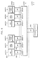
- Fig. 6 For purposes of illustration, it is assumed that the illustrative group structure shown in Fig. 6 is to be created. This group structure consists of two groups, 1 and 2, of user entities in layer n+1. Entities C through E are in group 1 and entities F through H are in group 2. It is further assumed that entity C is an SNA XID manager, entity D is a data user entity and entity E is an error processing manager. These functions are illustrative only. Other types of functions could be selected as well. It should be understood that access points can also provide system services that are required by a provider entity. One example of such a service might be the provision of error messages to an entity based on incoming blocks containing invalid data. Such system services can also be grouped by APs in accordance with the invention. Since the steps for creating separate groups are the same, only the creation of group 1 will be described.
- the n+1 layer manager Prior to the activation of an AP by a layer n+1 entity, the n+1 layer manager provides the layer n+1 entity with a group number. This can be accomplished either by including the group number in initial system configuration information for the n+1 entity or via separate messages that are transmitted between the n+1 layer manager and the n+1 entity.
- the layer manager 200 of the layer containing the grouped entities generates an activate group message. This message is sent to each of the service user entities (C, D and E in this example) of the intended group via an intra-layer communication function.
- This intra-layer communication function differs according to the particular type of system in which the layered architecture is implemented.
- the activate group message contains a unique, but otherwise arbitrary, GROUP identifier.
- each service user entity (C, D and E) generates an activate AP (ACT.AP) message.
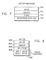
- An illustrative format of the ACT.AP message is shown in Fig. 7.
- This message contains an AP identifier (AP.ID) in field 700, the GROUP identifier passed by the layer manager 200 in field 704 and a TYPE identifier in field 706 that identifies the particular function provided by the layer n+1 service user entity generating the ACT.AP message.
- AP.IDs are predefined on the basis of data user types and layer manager functions.
- the ACT.AP message may also contain other information as well in field 708, but which is irrelevant to an understanding of the invention.
- Each ACT.AP message is sent to the appropriate layer n entity via interprocess communication provided by the operating system in question.
- interprocess communication might be the type provided by the well known OS/2 operating system, also marketed by IBM.
- Fig. 3 illustrates the above activate AP process.
- the steps in Fig. 3 are executed by each of the user entities in layer n+1 receiving the activate group message from the n+1 layer manager 200.
- each of the user entities C, D and E execute the steps shown in Fig. 3.
- Step 302 generates an ACT.AP message, which includes the GROUP identifier and the TYPE identification which identifies the type of function performed by the user entity in question. If it is assumed that user entity C is generating its ACT.AP message, the TYPE identification included in the ACT.AP message is XID management. Similarly, user entities D and E include their types (data user and error manager, respectively) in the ACT.AP messages that they generate.
- Step 304 sends the ACT.AP message in question to the layer n entity (entity B in this example) that is responsible for the routing of PIBs for this group.
- Fig. 4 shows the steps performed by an entity (for example, entity B) on receipt of each ACT.AP message.
- Step 400 creates an AP control block 800 (Fig. 8).
- the control block contains a field 802 for the AP.ID and additional fields 804 and 806 for the GROUP and TYPE identifications, respectively.
- the contents of fields 802, 804 and 806 are initialized by step 402.
- Field 808 contains a listing of the required functions in layer n+1 that a particular AP requires to complete its operations. These required functions can be provided as part of the configuration information that is provided as part of system definitions available on system startup or they may be provided in any other manner desired. For example, a AP connected to a layer n+1 data user (entity D) may require at least that an XID manager and an error logging manager be provided as user entities in layer n+1.
- An AP connected to an XID manager generally will not require any other user entity in layer n+1.
- an error logging manager entity E
- the specific functions in layer n+1 required by an AP in layer n are a matter of predefinition for the system or application at hand and are entered in field 808 when the control block is created.
- AP.IDs of the APs that are connected to the n+1 layer entities identified in field 808 are entered in field 810 in association with the field 808 entries as the appropriate APS are activated in the group.
- Step 404 searches the required functions field 808 to determine if a AP entry has been made for each required n+1 layer function in field 808.
- step 406 searches all present AP control blocks to see if an n+1 layer function exists for this group for each missing function listed in field 808. For each AP control block found for this group that is associated with a required function, step 408 updates field 810 with the AP.ID contained in the found AP control block for the required function. Once all existing AP control blocks have been searched, step 410 repeats the determination of whether or not all required n+1 layer functions for this AP have AP.ID entries in field 810. If all are satisfied, step 412 sends a confirm message to the layer n+1 user entity that generated the ACT.AP message that is now being processed.
- This confirm message also contains the AP.ID of the AP connecting the layer n and layer n+1 user entity.
- the layer n+1 entity and the layer n entity are effectively linked together via the same AP.
- the activation for this AP enters a pending state waiting to be satisfied by subsequent access point activations. All access points that have all of their required functions satisfied are confirmed at this time. The above steps will be repeated again when the next ACT.AP message is received by the layer n entity (B).
- step 418 determines if a AP to a layer n-1 entity (entity A in this example) already exists. Such a AP link could have been provided at an earlier time in conjunction with the creation of another group of entities in layer n+1. If the AP link to layer n-1 exists, the creation of the group 1 layer n+1 entities is complete and the program exits at step 420. If the link does not exist, step 422 generates a ACT.AP message to create the link and step 424 sends the message to the layer n-1 manager via interprocess communication.
- a AP to a layer n-1 entity entity A in this example
- TYPE in this message will be null for this illustrative example, since AP type is not relevant for entity A in this illustrative example. However, it will be clear that TYPE could be included to establish some other type of grouping between the layers.
- the AP.ID for the data user entity D is used for addressing in all PIBs that are received for this logical group. While this is arbitrary, the use of data user entities such as D for addressing purposes in the PIB headers is more efficient than the use of other n+1 layer entities of the group, since the bulk of all PIBs to the group will ordinarily be to the data user entity.
- layer n+1, layer n, etc. may refer to any layer of the architecture. However, as mentioned earlier, this illustrative embodiment is concerned only with the first three layers (physical, data link and network).
- step 500 strips the header information pertinent to this layer from the PIB header.
- step 502 determines the AP.ID of the data user entity D from in the stripped information.
- Step 502 also determines the TYPE of the PIB by examining the header information.
- Step 504 determines if the PIB type is relevant at the layer processing the PIB. It does this in the preferred embodiment by examining the TYPE field 806 of the AP control block associated with the layer and AP.ID (the TYPE field in layers where type is not relevant will be set to an "ignore" state). If TYPE is "ignore", then the PIB type for this layer is not relevant. Thus, in the preferred embodiment, for a PIB arriving at entity A, PIB type is not relevant and step 514 merely routes the PIB to the AP identified in the PIB header (AP 608). This routes the PIB to entity B in the data link layer.
- RCV_DATA_BLK A separate instance of RCV_DATA_BLK is also running at layer n and n+1.
- step 504 determines that the PIB type is relevant (the TYPE field 506 is not set to "ignore" in layer n).
- Step 506 determines the type of the PIB by examining the PIB header and compares it with the contents of the TYPE field 806.
- the TYPE field 806 in the AP control block in layer n is associated with the data user entity D in layer n+1.
- step 508 If the PIB is a data PIB, i.e., a PDB, the match is successful (step 508) and step 514 routes the PDB to the data user entity via the associated AP 604. If the PIB is not a PDB, steps 506 and 508 do not find a match. In this case, step. 510 searches the required function field 810 until it locates a match on TYPE. Step 512 then routes the PIB to the layer n+1 entity linked to the AP.ID that is associated with the found TYPE match.
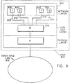
- Fig. 9 shows one physical embodiment in which the above invention might be used.
- This particular example involves a desktop computer 900, such as a PS/2, which is interfaced to a local area network (LAN) 902 by means of an interface card 904 inserted into the computer.
- the LAN might be a token ring network, for example.
- the card 904 implements a layered communication architecture in accordance with the teaching of the invention.
- An entity A in the physical layer sends and receives information to and from the LAN 902. Entity A is linked to entity B in the data link control layer by a AP 906.
- AP 906 Two logical groups of entities have been created in the network layer to which entity B is linked by APs 908 through 914.
- management entities 918 and 920 in the network layer have been created for the two groups 1 and 2. These two management entities are respectively associated with the user data entities 922 and 924 in the respective groups 1 and 2.
- the management entities establish and teardown connections to other nodes on the LAN 902. They may perform other control functions as well.
- the data user entities receive the data information destined for a higher layer or for user applications (not shown). Usually, but not always, the data user entities link to the next upper transport layer to pass data PDBs on to the data user applications.
Landscapes
- Engineering & Computer Science (AREA)
- Computer Security & Cryptography (AREA)
- Computer Networks & Wireless Communication (AREA)
- Signal Processing (AREA)
- Communication Control (AREA)
- Small-Scale Networks (AREA)
Applications Claiming Priority (2)
| Application Number | Priority Date | Filing Date | Title |
|---|---|---|---|
| US07/588,214 US5245608A (en) | 1990-09-26 | 1990-09-26 | Logical grouping of layer entities in a layered communication architecture |
| US588214 | 1990-09-26 |
Publications (2)
| Publication Number | Publication Date |
|---|---|
| EP0478486A2 true EP0478486A2 (de) | 1992-04-01 |
| EP0478486A3 EP0478486A3 (en) | 1995-01-04 |
Family
ID=24352953
Family Applications (1)
| Application Number | Title | Priority Date | Filing Date |
|---|---|---|---|
| EP91480131A Withdrawn EP0478486A3 (en) | 1990-09-26 | 1991-08-29 | Method and system for providing communication in a layered communication architecture |
Country Status (3)
| Country | Link |
|---|---|
| US (1) | US5245608A (de) |
| EP (1) | EP0478486A3 (de) |
| JP (1) | JPH0720162B2 (de) |
Cited By (4)
| Publication number | Priority date | Publication date | Assignee | Title |
|---|---|---|---|---|
| EP0572865A3 (de) * | 1992-05-26 | 1994-03-16 | Alcatel Nv | |
| WO1995034982A3 (en) * | 1994-06-13 | 1996-02-08 | Ericsson Telefon Ab L M | Method and system for providing communication services between two layered networks |
| EP0565472A3 (en) * | 1992-04-10 | 1996-08-28 | Ibm | Method and apparatus for sharing a telecommunications channel among multiple users |
| WO1997036410A1 (en) * | 1996-03-25 | 1997-10-02 | Nokia Telecommunications Oy | Method for data flow control between layers of a layered communication protocol |
Families Citing this family (29)
| Publication number | Priority date | Publication date | Assignee | Title |
|---|---|---|---|---|
| US5519875A (en) * | 1991-08-08 | 1996-05-21 | Hitachi, Ltd. | Distributed processing system for modules, each having modularized objects |
| FR2687878A1 (fr) * | 1992-02-21 | 1993-08-27 | Bull Sa | Systeme de relais de transport osi entre reseau en mode connecte et un reseau en mode non connecte. |
| EP0584027A2 (de) * | 1992-08-19 | 1994-02-23 | International Business Machines Corporation | Transparente Übertragung zwischen gleiche Schichten in einer schichtorientierten Kommunikationsarchitektur |
| US5978577A (en) * | 1995-03-17 | 1999-11-02 | Csg Systems, Inc. | Method and apparatus for transaction processing in a distributed database system |
| DE69628073D1 (de) | 1995-03-22 | 2003-06-18 | Sun Microsystems Inc | Vorrichtung und Verfahren zur Verwaltung von Objektsammlungen |
| US8606851B2 (en) | 1995-06-06 | 2013-12-10 | Wayport, Inc. | Method and apparatus for geographic-based communications service |
| US5835061A (en) * | 1995-06-06 | 1998-11-10 | Wayport, Inc. | Method and apparatus for geographic-based communications service |
| US5784567A (en) * | 1995-12-13 | 1998-07-21 | Silicon Graphics, Inc. | System and method for coordinating communication between layers of a layered communication system |
| JP3027389U (ja) * | 1996-01-30 | 1996-08-09 | 有限会社市川商店 | 絹製洗浄用具 |
| US5822523A (en) | 1996-02-01 | 1998-10-13 | Mpath Interactive, Inc. | Server-group messaging system for interactive applications |
| DE19713956C2 (de) * | 1997-04-04 | 1999-02-18 | Ericsson Telefon Ab L M | Verfahren, Kommunikationsnetz und Dienst-Zugangs-Interface für Kommunikationen in einer Umgebung für Verbindungen von offenen Systemen |
| AU773884B2 (en) | 1999-11-03 | 2004-06-10 | Cisco Technology, Inc. | Distributed network communication system which enables multiple network providers to use a common distributed network infrastructure |
| US7187676B2 (en) * | 2002-06-04 | 2007-03-06 | Sun Microsystems, Inc. | Apparatus and method for steering a communication to an open stream |
| US8027280B2 (en) * | 2004-10-27 | 2011-09-27 | Honeywell International Inc. | Layered architecture for data management in a wireless sensor network |
| US7664080B2 (en) * | 2004-10-27 | 2010-02-16 | Honeywell International Inc. | Discreet event operators for event management in a wireless sensor network |
| US7630336B2 (en) * | 2004-10-27 | 2009-12-08 | Honeywell International Inc. | Event-based formalism for data management in a wireless sensor network |
| US7590098B2 (en) * | 2004-10-27 | 2009-09-15 | Honeywell International Inc. | Publish/subscribe model in a wireless sensor network |
| US7561544B2 (en) * | 2004-10-27 | 2009-07-14 | Honeywell International Inc. | Machine architecture for event management in a wireless sensor network |
| US7715308B2 (en) * | 2004-12-09 | 2010-05-11 | Honeywell International Inc. | Fault tolerance in a wireless network |
| US8761751B2 (en) | 2008-03-14 | 2014-06-24 | William J. Johnson | System and method for targeting data processing system(s) with data |
| US8923806B2 (en) | 2008-03-14 | 2014-12-30 | William J. Johnson | System and method for presenting application data by data processing system(s) in a vicinity |
| US8634796B2 (en) | 2008-03-14 | 2014-01-21 | William J. Johnson | System and method for location based exchanges of data facilitating distributed location applications |
| US8600341B2 (en) | 2008-03-14 | 2013-12-03 | William J. Johnson | System and method for location based exchanges of data facilitating distributed locational applications |
| US8639267B2 (en) | 2008-03-14 | 2014-01-28 | William J. Johnson | System and method for location based exchanges of data facilitating distributed locational applications |
| US8566839B2 (en) | 2008-03-14 | 2013-10-22 | William J. Johnson | System and method for automated content presentation objects |
| US9626446B2 (en) | 2012-03-07 | 2017-04-18 | Snap Trends, Inc. | Methods and systems of advertising based on aggregated information of social networks within geographical locations via a network |
| US9411857B1 (en) | 2013-06-28 | 2016-08-09 | Google Inc. | Grouping related entities |
| US9477991B2 (en) | 2013-08-27 | 2016-10-25 | Snap Trends, Inc. | Methods and systems of aggregating information of geographic context regions of social networks based on geographical locations via a network |
| US9894489B2 (en) | 2013-09-30 | 2018-02-13 | William J. Johnson | System and method for situational proximity observation alerting privileged recipients |
Family Cites Families (4)
| Publication number | Priority date | Publication date | Assignee | Title |
|---|---|---|---|---|
| JPS63209246A (ja) * | 1987-02-25 | 1988-08-30 | Hitachi Ltd | 受信バツフア割当て方式 |
| JP2826122B2 (ja) * | 1988-09-22 | 1998-11-18 | 株式会社リコー | データ端末装置およびその伝送制御方法 |
| US4991133A (en) * | 1988-10-07 | 1991-02-05 | International Business Machines Corp. | Specialized communications processor for layered protocols |
| US5124984A (en) * | 1990-08-07 | 1992-06-23 | Concord Communications, Inc. | Access controller for local area network |
-
1990
- 1990-09-26 US US07/588,214 patent/US5245608A/en not_active Expired - Lifetime
-
1991
- 1991-08-12 JP JP3226603A patent/JPH0720162B2/ja not_active Expired - Lifetime
- 1991-08-29 EP EP91480131A patent/EP0478486A3/en not_active Withdrawn
Cited By (5)
| Publication number | Priority date | Publication date | Assignee | Title |
|---|---|---|---|---|
| EP0565472A3 (en) * | 1992-04-10 | 1996-08-28 | Ibm | Method and apparatus for sharing a telecommunications channel among multiple users |
| EP0572865A3 (de) * | 1992-05-26 | 1994-03-16 | Alcatel Nv | |
| WO1995034982A3 (en) * | 1994-06-13 | 1996-02-08 | Ericsson Telefon Ab L M | Method and system for providing communication services between two layered networks |
| WO1997036410A1 (en) * | 1996-03-25 | 1997-10-02 | Nokia Telecommunications Oy | Method for data flow control between layers of a layered communication protocol |
| US6614807B1 (en) | 1996-03-25 | 2003-09-02 | Nokia Corporation | Method for data flow control between layers of a layered communication protocol |
Also Published As
| Publication number | Publication date |
|---|---|
| US5245608A (en) | 1993-09-14 |
| JPH04258065A (ja) | 1992-09-14 |
| EP0478486A3 (en) | 1995-01-04 |
| JPH0720162B2 (ja) | 1995-03-06 |
Similar Documents
| Publication | Publication Date | Title |
|---|---|---|
| US5245608A (en) | Logical grouping of layer entities in a layered communication architecture | |
| EP0169455B1 (de) | Nicht eindeutige Namen für Rundschreibnachrichten | |
| US5377262A (en) | Telecommunication switching system having adaptive routing switching nodes | |
| EP0584027A2 (de) | Transparente Übertragung zwischen gleiche Schichten in einer schichtorientierten Kommunikationsarchitektur | |
| US4941089A (en) | Input/output network for computer system | |
| EP0493912B1 (de) | Transparente Fernsteuerung eines Vermittlungsnetzes über eine Standardschnittstellenverbindung | |
| Wecker | DNA: the digital network architecture | |
| JPH08507909A (ja) | ワークステーションを複数個のコンピュータプラットホームにインタフェースする方法および装置 | |
| US6421317B1 (en) | Method and apparatus for an automatic load balancing and back-up of a multi-users network | |
| JP2526695B2 (ja) | オンライン情報処理装置 | |
| CN1333613A (zh) | 能够发送标记帧的虚拟局域网系统 | |
| US4551834A (en) | Method and system for communicating over an open communication network | |
| WO1997050215A1 (en) | System and method for transferring packets in a 'connectionless' network | |
| WO2006068434A1 (en) | Communication network system of bus network structure and message routing method using the system | |
| US6865178B1 (en) | Method and system for establishing SNA connection through data link switching access services over networking broadband services | |
| US20160365987A1 (en) | Personal computer network | |
| US6334155B1 (en) | Method and apparatus for connecting similar stacks without using physical devices | |
| JPH0210947A (ja) | 伝送制御方法 | |
| US6076116A (en) | Local area network comprising distributed switching software | |
| JP3445896B2 (ja) | B−isdn端末間のマルチコネクション制御方式 | |
| WO2006065102A1 (en) | Communication network system of bus network structure and method for transmitting and receiving data using the system | |
| AU1943600A (en) | Method of communication between distant objects | |
| JPH06268682A (ja) | プロトコル変換システム | |
| KR20000024801A (ko) | 에이알시 네트워크의 데이터 다중 처리 방법 | |
| EP0314909B1 (de) | Vorstellung des Bildes eines einzigen Knotens für einen Netzwerkknoten mit mehreren Prozessoren |
Legal Events
| Date | Code | Title | Description |
|---|---|---|---|
| PUAI | Public reference made under article 153(3) epc to a published international application that has entered the european phase |
Free format text: ORIGINAL CODE: 0009012 |
|
| AK | Designated contracting states |
Kind code of ref document: A2 Designated state(s): DE FR GB |
|
| 17P | Request for examination filed |
Effective date: 19920817 |
|
| PUAL | Search report despatched |
Free format text: ORIGINAL CODE: 0009013 |
|
| AK | Designated contracting states |
Kind code of ref document: A3 Designated state(s): DE FR GB |
|
| STAA | Information on the status of an ep patent application or granted ep patent |
Free format text: STATUS: THE APPLICATION HAS BEEN WITHDRAWN |
|
| 18W | Application withdrawn |
Withdrawal date: 19960704 |