EP0478760B1 - Drehmoment-schraubenschlüssel - Google Patents
Drehmoment-schraubenschlüssel Download PDFInfo
- Publication number
- EP0478760B1 EP0478760B1 EP91908708A EP91908708A EP0478760B1 EP 0478760 B1 EP0478760 B1 EP 0478760B1 EP 91908708 A EP91908708 A EP 91908708A EP 91908708 A EP91908708 A EP 91908708A EP 0478760 B1 EP0478760 B1 EP 0478760B1
- Authority
- EP
- European Patent Office
- Prior art keywords
- piston
- pistons
- torque wrench
- engaging
- drive means
- Prior art date
- Legal status (The legal status is an assumption and is not a legal conclusion. Google has not performed a legal analysis and makes no representation as to the accuracy of the status listed.)
- Expired - Lifetime
Links
Images


Classifications
-
- B—PERFORMING OPERATIONS; TRANSPORTING
- B25—HAND TOOLS; PORTABLE POWER-DRIVEN TOOLS; MANIPULATORS
- B25B—TOOLS OR BENCH DEVICES NOT OTHERWISE PROVIDED FOR, FOR FASTENING, CONNECTING, DISENGAGING, OR HOLDING
- B25B21/00—Portable power-driven screw or nut setting or loosening tools; Attachments for drilling apparatus serving the same purpose
- B25B21/004—Portable power-driven screw or nut setting or loosening tools; Attachments for drilling apparatus serving the same purpose of the ratchet type
- B25B21/005—Portable power-driven screw or nut setting or loosening tools; Attachments for drilling apparatus serving the same purpose of the ratchet type driven by a radially acting hydraulic or pneumatic piston
Definitions
- the present invention relates to a torque wrench. More particularly, it relates to such a torque wrench which has an engaging unit which engages a threaded connector and is turned so as to turn the threaded connector for tightening or loosening, and a fluid-operated drive unit including a cylinder and a piston movable in the cylinder and acting upon the engaging unit to turn the latter.
- Torque wrenches of the above-mentioned general type are widely known in the art.
- the torque output of fluid-operated torque wrenches is based on the torque capacity of the engaging unit which can include for example a square drive, or in other words a square projection to which standard impact sockets can be attached.
- a 2.5 cm (1 inch) square drive cannot take more than 4200 N m (3,100 ft./lbs.) since a torque higher than this would break off the square drive.
- a 3.8 cm (1.5 inch) square drive cannot take more than 16250 N m (12,000 ft./lbs.). Therefore the tools are designed so that the maximum torque output at maximum pressure does not exceed the maximum torque capacity of a square drive. It is therefore desirable to provide such a torque wrench in which the maximum torque output can be adjusted to the maximum torque capacity of a respective square drive, in a simple, convenient and fool-proof manner, since an error in selecting the maximum torque output can lead to destruction of the square drive.
- a torque wrench for tightening or loosening a threaded connector is disclosed for example in my US-A 4 825 730. It has turnable engaging means arranged to be turned and to engage a threaded connector so as to tighten and loosen the latter in response to turning of the engaging means, power drive means for turning the engaging means to perform a stroke, means for connecting the power drive means with the engaging means, and exchangeable auxiliary elements connectable with said power drive means.
- the torque wrench of this reference does not allow application of a smaller pressure or a greater pressure correspondingly.
- Another device is disclosed in the German document DE-A-1964076 but this does not disclose specially designed means for simple and efficient variation of a pressure applied by the device.
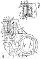
- FIG. 1 A torque wrench for tightening or loosening threaded connectors in accordance with the present invention is shown in FIG. 1.
- the torque wrench includes an engaging unit 1 which is turnable and is formed to engage a threaded connector 2 so that when the engaging unit 1 engages a threaded connector and is turned, it turns the threaded connector for tightening or loosening the same.
- the torque wrench includes further a fluid-operated power drive 2 which acts upon and turns the engaging unit 1 for tightening or loosening a threaded connector.
- the engaging unit 1 includes a ratchet wheel 3 which has a plurality of outer teeth and is provided with an engaging formation which is formed for example as a hexagonal projection 4 for attaching respective sockets to the projection.
- the sockets can be fitted on the threaded connectors, such as for example, nuts, bolt heads, etc.
- the engaging formation 4 can also be formed as a hexagonal opening which is directly fittable on the above mentioned threaded connectors.
- the engaging unit 1 further has a drive lever 5 which in its lower end is provided with a circular opening for rotatably receiving the ratchet wheel 3, and on its upper end is provided with a substantially circular head 6.
- a pawl 7 is displaceable in a recess of the lever 5 and provided with a plurality of teeth which engage with the teeth of the ratchet wheel 3.
- the pawl 7 is for example spring biased toward the ratchet 3.
- Two links or auxiliary elements 8 surround the lever 5 and are provided with a central opening 9 which also rotatably receives the ratchet 3.
- the links 8 have mounting openings 10 and 11 through which pins 12 and 13 extend for removably mounting the links 8 to a housing of the torque wrench.
- FIG. 2 shows one of the links 8 or auxiliary elements which is designed for the ratchet 3 suitable for a greater torque capacity, while one of the links or auxiliary elements 8' shown in FIG. 3 is designed for a ratchet having a lower torque capacity, as will be explained in detail hereinbelow.
- the difference between the links 8' of FIG. 3 and the links 8 of FIG. 2 is that the links 8' are provided with a projection 14.
- the fluid-operated power drive unit 2 includes a cylinder 15 which can be formed as a part of the housing of the torque wrench, and two pistons 16 and 17.
- the pistons 16 and 17 are cup-shaped, and the inner piston 17 is arranged in the interior of the outer piston 16.
- the inner piston 17 is connected with an intermediate piece 18 which in turn is pivotably connected with a bracket 19.
- the bracket 19 has a recess in which the head 6 of the lever 5 is received in a slidable and turnable manner.
- the bracket 19 can be spring biased toward the lever 5.
- a supply opening 20 is provided for supplying a working fluid into the cylinder 15 to the pistons 16 and 17 from a not shown source.
- the supply line 20 has an outlet 20' which opens behind the right end face of the piston 16 and an outlet 20'' which opens behind the right end of the piston 17.
- Additional piston means is further provided in an inner chamber 21 of the inner piston 17.
- the additional piston means is immovable relative to the cylinder 15 and includes an additional piston 22 provided with a piston rod 23.
- a throughgoing opening 24 extends through the piston rod 23 and has one end which opens through a passage 24' into the inner chamber 21 and the other end which is connected with a supply line 25 extending from a not shown source of a working fluid.
- the torque wrench in accordance with the present invention operates in the following manner.
- the links 8 are mounted in the torque wrench and a working fluid is supplied through the line 20 and outlet 20', 20'' into the cylinder 15, it applies pressure to both pistons 16 and 17 which have a relatively great combined piston area.
- Both pistons 16 and 17 are displaced to the left as shown in FIG. 1a, since the links 8 do not have a limiting projection, and in turn displace the intermediate piece 18 and the bracket 19 to the left so as to turn the lever 5 in a counterclockwise direction.
- the pawl 7 connected with the lever 5 turns the ratchet wheel 3 in the counterclockwise direction so as to tighten or loosen a threaded connector engaged by the engaging formation 4.
- FIG. 4 shows another embodiment of the torque wrench of the present invention.
- the return means for returning the pistons to their initial position does not have additional piston means 22, 23, 24 as in the embodiment of FIG. 1.
- the return means includes a spring drive 27 which cooperates with a projection 25 of a bracket 19'.
- the spring 27 is compressed.
- the spring 27 applies a return pressure against the projection 28 of the bracket 19', displaces the bracket 19' to the right, and turns the lever 5 in the clockwise direction.
Landscapes
- Engineering & Computer Science (AREA)
- Mechanical Engineering (AREA)
- Details Of Spanners, Wrenches, And Screw Drivers And Accessories (AREA)
- Hand Tools For Fitting Together And Separating, Or Other Hand Tools (AREA)
- Actuator (AREA)
- Fluid-Pressure Circuits (AREA)
Claims (10)
- Drehmoment-Schraubenschlüssel zum Festziehen oder Lösen von Gewindeverbindungsstücken, der ein drehbares Eingriffsmittel (1), das so angeordnet ist, daß es gedreht werden und in ein Gewindeverbindungsstück eingreifen kann, um das letztgenannte aufgrund der Drehung des genannten Eingriffsmittels festzuziehen oder zu lösen; ein Kraftantriebsmittel (2) zum Drehen des genannten Eingriffsmittels (1), um einen Arbeitshub durchführen zu können; Mittel zur Verbindung des genannten Kraftantriebsmittels mit dem genannten Eingriffsmittel; sowie zumindest zwei auswechselbare Hilfselemente (8, 8') umfaßt, die in lösbarer Weise mit dem genannten Kraftantriebsmittel (2) verbunden werden können, dadurch gekennzeichnet, daß- das genannte Kraftantriebsmittel (2) medienbetätigte Zylinder/Kolben-Mittel (15, 16, 17) umfaßt, die einen Zylinder (15) und zwei Kolben (16, 17) aufweisen, wobei die genannten Kolben (16, 17) so bewegbar sind, daß während des genannten Arbeitshubes, wenn ein Kolben (17) mit einer kleineren Kolbenfläche bewegt wird, dieser Kolben einen geringeren Druck auf das genannte Eingriffsmittel (1) ausübt, um so ein niedrigeres Drehmoment bereitzustellen, während die beiden genannten Kolben (16, 17), wenn sie gemeinsam mit einer größeren Gesamtkolbenfläche bewegt werden, einen größeren Druck auf das genannte Eingriffsmittel (1) ausüben, um so ein höheres Drehmoment bereitzustellen, und- ein erstes (8') der genannten Hilfselemente so ausgebildet ist, daß es die Bewegung des anderen (16) der genannten Kolben des genannten medienbetätigten Antriebsmittels (2) blockiert, um lediglich eine Bewegung des genannten einen Kolbens (17) zuzulassen, während ein zweites Hilfselement (8) so ausgebildet ist, daß es eine Bewegung des genannten anderen (16) der genannten Kolben zuläßt.
- Drehmoment-Schraubenschlüssel nach Anspruch 1, wobei zumindest einer (16) der genannten Kolben des genannten medienbetätigten Antriebsmittels (2) hohl ausgeführt ist und einen Innenraum besitzt und der andere (17) der genannten Kolben des genannten medienbetätigten Antriebsmittels (2) im genannten Innenraum des genannten einen Kolbens (16) angeordnet ist.
- Drehmoment-Schraubenschlüssel nach Anspruch 1 oder Anspruch 2, wobei einer (16) der genannten Kolben mit dem genannten Eingriffsmittel (1) verbunden ist; und weiterhin Verbindungsmittel (18, 19) vorgesehen sind, um den genannten einen Kolben (16) mit dem genannten Eingriffsmittel (1) zu verbinden.
- Drehmoment-Schraubenschlüssel nach einem der vorstehenden Ansprüche, wobei das genannte Kraftantriebsmittel (2) so angeordnet ist, daß es das genannte Eingriffsmittel (1) in eine erste Richtung drehen kann; und weiterhin Rückführungsmittel (22, 23, 24; 27) angeordnet sind, um das genannte Eingriffsmittel (1) in eine entgegengesetzte Richtung zu drehen.
- Drehmoment-Schraubenschlüssel nach Anspruch 4, wobei das genannte Rückführungsmittel (27), mit dem das genannte Eingriffsmittel in eine entgegengesetzte Richtung gedreht werden kann, ein Federmittel (27) umfaßt, das auf das genannte Eingriffsmittel (1) einwirkt.
- Drehmoment-Schraubenschlüssel nach Anspruch 4, wobei einer (17) der genannten Kolben eine Innenkammer (21) besitzt und die genannten Rückführungsmittel (22, 23, 24) ein Element umfassen, das eine durchgehende Öffnung (24) aufweist, die sich in die genannte Innenkammer (21) öffnet, so daß die genannten Kolben (16, 17), wenn ein Arbeitsmedium durch die genannte Öffnung (24) in die genannte Innenkammer (21) gelangt, so bewegt werden, daß sie das genannte Eingriffsmittel (1) in eine entgegengesetzte Richtung bewegen.
- Drehmoment-Schraubenschlüssel nach Anspruch 6, wobei das genannte Rückführungsmittel (22, 23, 24) einen zusätzlichen Kolben (22) umfaßt, der so angeordnet ist, daß er an den genannten einen Kolben (17) stößt, und eine Kolbenstange (23) mit dem genannten zusätzlichen Kolben (22) verbunden ist, wobei die genannte durchgehende Öffnung (24) in der genannten Kolbenstange (23) des genannten Kolbenmittels vorgesehen ist.
- Drehmoment-Schraubenschlüssel nach einem der vorstehenden Ansprüche, wobei das genannte erste Hilfselement (8') in lösbarer Weise mit dem genannten Kraftantriebsmittel (2) verbunden werden kann.
- Drehmoment-Schraubenschlüssel nach einem der vorstehenden Ansprüche, wobei das genannte erste Hilfselement (8') einen Vorsprung (14) aufweist, der in Richtung auf den genannten anderen Kolben (16) des genannten medienbetätigten Antriebsmittels (2) verläuft und eine Bewegung des genannten anderen Kolbens (16) verhindert.
- Drehmoment-Schraubenschlüssel nach Anspruch 9, wobei das genannte zweite Hilfselement (8) in lösbarer Weise mit dem genannten Kraftantriebsmittel (2) verbunden werden kann und so ausgebildet ist, daß es eine gemeinsame Bewegung der beiden genannten Kolben (16, 17) des genannten medienbetätigten Antriebsmittels (2) zuläßt.
Applications Claiming Priority (3)
| Application Number | Priority Date | Filing Date | Title |
|---|---|---|---|
| US505976 | 1990-04-06 | ||
| US07/505,976 US5005447A (en) | 1989-10-05 | 1990-04-06 | Torque wrench |
| PCT/US1991/002469 WO1991015338A1 (en) | 1990-04-06 | 1991-04-08 | Torque wrench |
Publications (3)
| Publication Number | Publication Date |
|---|---|
| EP0478760A1 EP0478760A1 (de) | 1992-04-08 |
| EP0478760A4 EP0478760A4 (en) | 1992-10-14 |
| EP0478760B1 true EP0478760B1 (de) | 1994-12-07 |
Family
ID=24012659
Family Applications (1)
| Application Number | Title | Priority Date | Filing Date |
|---|---|---|---|
| EP91908708A Expired - Lifetime EP0478760B1 (de) | 1990-04-06 | 1991-04-08 | Drehmoment-schraubenschlüssel |
Country Status (7)
| Country | Link |
|---|---|
| US (1) | US5005447A (de) |
| EP (1) | EP0478760B1 (de) |
| JP (1) | JPH0714593B2 (de) |
| AT (1) | ATE115026T1 (de) |
| DE (1) | DE69105688T2 (de) |
| ES (1) | ES2067931T3 (de) |
| WO (1) | WO1991015338A1 (de) |
Families Citing this family (13)
| Publication number | Priority date | Publication date | Assignee | Title |
|---|---|---|---|---|
| FR2657039B1 (fr) * | 1990-01-13 | 1996-01-05 | Wagner Paul Heinz | Visseuse motorisee entrainee par la pression. |
| DE4042070C2 (de) * | 1990-01-13 | 1995-06-08 | Wagner Paul Heinz | Druckmittelbetriebener Kraftschrauber |
| US5329833A (en) * | 1992-07-31 | 1994-07-19 | Sergan Anthony J | Bimodal hydraulic reciprocating torque actuator |
| US6112622A (en) * | 1999-05-03 | 2000-09-05 | Unex Corporation | Fluid-operated tool |
| US6260444B1 (en) | 1999-06-23 | 2001-07-17 | John K. Junkers | Power tool |
| GB0014416D0 (en) * | 2000-06-13 | 2000-08-09 | More Nicholas | Hydraulic torque wrench |
| US6546839B1 (en) | 2000-08-22 | 2003-04-15 | Titantechnologies International, Inc. | Flow regulation device |
| US6802235B2 (en) * | 2002-01-04 | 2004-10-12 | Unex Corporation | Fluid-operated torque wrench |
| MX2010002058A (es) * | 2010-02-22 | 2011-08-31 | Luis Gerardo Oyervides Ochoa | Llave hidraulica de accionamiento manual para aprietes y desaprietes de alto par. |
| US9550282B2 (en) * | 2014-04-22 | 2017-01-24 | John D. Davis | Compact hydraulic torque wrench cartridge |
| GB2558536A (en) * | 2016-11-14 | 2018-07-18 | Torque Tension Systems Ltd | A hydraulic torque wrench |
| AU2018241199A1 (en) * | 2017-10-06 | 2019-05-02 | Enerpac Tool Group Corp. | Industrial tool and drive system for same |
| USD1042067S1 (en) * | 2023-02-28 | 2024-09-17 | Primesource Consulting Llc | Limited clearance tool |
Family Cites Families (7)
| Publication number | Priority date | Publication date | Assignee | Title |
|---|---|---|---|---|
| DE1964076C3 (de) * | 1969-12-22 | 1978-04-27 | G.L. Rexroth Gmbh, 8770 Lohr | Arbeitszylinder mit Eilgang und Krafthub |
| JPS5336800A (en) * | 1976-09-16 | 1978-04-05 | Sumitomo Metal Ind | Hydraulic wrench |
| JPS53117174A (en) * | 1977-03-22 | 1978-10-13 | Sakunao Tanaka | Double cylinder structure and operating device thereof |
| US4524651A (en) * | 1981-04-03 | 1985-06-25 | Paul-Heinz Wagner | Power wrench |
| DE8435272U1 (de) * | 1984-12-01 | 1985-02-28 | Wagner, Paul-Heinz, 5203 Much | Hydraulischer kraftschrauber |
| US4825730A (en) * | 1987-09-29 | 1989-05-02 | Junkers John K | Fluid operated wrench |
| JP5433000B2 (ja) | 2009-07-02 | 2014-03-05 | オリヒロエンジニアリング株式会社 | 縦型充填包装機および、内容物入り包装袋の製造方法 |
-
1990
- 1990-04-06 US US07/505,976 patent/US5005447A/en not_active Expired - Lifetime
-
1991
- 1991-04-08 JP JP3508346A patent/JPH0714593B2/ja not_active Expired - Lifetime
- 1991-04-08 ES ES91908708T patent/ES2067931T3/es not_active Expired - Lifetime
- 1991-04-08 DE DE69105688T patent/DE69105688T2/de not_active Expired - Fee Related
- 1991-04-08 EP EP91908708A patent/EP0478760B1/de not_active Expired - Lifetime
- 1991-04-08 WO PCT/US1991/002469 patent/WO1991015338A1/en not_active Ceased
- 1991-04-08 AT AT91908708T patent/ATE115026T1/de not_active IP Right Cessation
Also Published As
| Publication number | Publication date |
|---|---|
| US5005447A (en) | 1991-04-09 |
| EP0478760A1 (de) | 1992-04-08 |
| ATE115026T1 (de) | 1994-12-15 |
| JPH0714593B2 (ja) | 1995-02-22 |
| DE69105688D1 (de) | 1995-01-19 |
| WO1991015338A1 (en) | 1991-10-17 |
| ES2067931T3 (es) | 1995-04-01 |
| EP0478760A4 (en) | 1992-10-14 |
| DE69105688T2 (de) | 1995-04-20 |
| JPH04503778A (ja) | 1992-07-09 |
Similar Documents
| Publication | Publication Date | Title |
|---|---|---|
| US4825730A (en) | Fluid operated wrench | |
| US5005447A (en) | Torque wrench | |
| EP1063060B1 (de) | Angetriebenes Werkzeug | |
| USRE33951E (en) | Fluid operated wrench | |
| US6298752B1 (en) | Continuous fluid-operated wrench | |
| US5016502A (en) | Power wrench | |
| US4706526A (en) | Fluid operated wrench | |
| EP1052067B1 (de) | Druckmittelbetriebenes Werkzeug | |
| US4663997A (en) | Fluid-operated wrench | |
| CA2412817C (en) | Torque wrench | |
| EP0386355A1 (de) | Kraftschrauber | |
| US5029497A (en) | Continuous ratchet drive | |
| AU2001266144A1 (en) | Torque wrench | |
| EP1086785B1 (de) | Druckmittel betätigtes Werkzeug | |
| EP0504331B1 (de) | Hydraulisch betriebener schraubenschlüssel | |
| EP0324050A1 (de) | Kraftschrauber | |
| US3466953A (en) | Ratchet wrench with hydraulically operated lock | |
| JPS634619Y2 (de) | ||
| HK1030390B (en) | Power tool | |
| HK1036244A (en) | Fluid-operated tool | |
| AU5660600A (en) | Power tool |
Legal Events
| Date | Code | Title | Description |
|---|---|---|---|
| PUAI | Public reference made under article 153(3) epc to a published international application that has entered the european phase |
Free format text: ORIGINAL CODE: 0009012 |
|
| AK | Designated contracting states |
Kind code of ref document: A1 Designated state(s): AT BE CH DE DK ES FR GB GR IT LI LU NL SE |
|
| 17P | Request for examination filed |
Effective date: 19920316 |
|
| A4 | Supplementary search report drawn up and despatched |
Effective date: 19920827 |
|
| AK | Designated contracting states |
Kind code of ref document: A4 Designated state(s): AT BE CH DE DK ES FR GB GR IT LI LU NL SE |
|
| 17Q | First examination report despatched |
Effective date: 19930826 |
|
| GRAA | (expected) grant |
Free format text: ORIGINAL CODE: 0009210 |
|
| ITF | It: translation for a ep patent filed | ||
| AK | Designated contracting states |
Kind code of ref document: B1 Designated state(s): AT BE CH DE DK ES FR GB GR IT LI LU NL SE |
|
| PG25 | Lapsed in a contracting state [announced via postgrant information from national office to epo] |
Ref country code: GR Free format text: LAPSE BECAUSE OF FAILURE TO SUBMIT A TRANSLATION OF THE DESCRIPTION OR TO PAY THE FEE WITHIN THE PRESCRIBED TIME-LIMIT Effective date: 19941207 Ref country code: DK Effective date: 19941207 |
|
| REF | Corresponds to: |
Ref document number: 115026 Country of ref document: AT Date of ref document: 19941215 Kind code of ref document: T |
|
| REF | Corresponds to: |
Ref document number: 69105688 Country of ref document: DE Date of ref document: 19950119 |
|
| REG | Reference to a national code |
Ref country code: GR Ref legal event code: FG4A Free format text: 3014496 |
|
| ET | Fr: translation filed | ||
| PGFP | Annual fee paid to national office [announced via postgrant information from national office to epo] |
Ref country code: LU Payment date: 19950401 Year of fee payment: 5 |
|
| REG | Reference to a national code |
Ref country code: ES Ref legal event code: FG2A Ref document number: 2067931 Country of ref document: ES Kind code of ref document: T3 |
|
| PGFP | Annual fee paid to national office [announced via postgrant information from national office to epo] |
Ref country code: GB Payment date: 19950403 Year of fee payment: 5 |
|
| PGFP | Annual fee paid to national office [announced via postgrant information from national office to epo] |
Ref country code: ES Payment date: 19950410 Year of fee payment: 5 |
|
| PGFP | Annual fee paid to national office [announced via postgrant information from national office to epo] |
Ref country code: SE Payment date: 19950411 Year of fee payment: 5 |
|
| PGFP | Annual fee paid to national office [announced via postgrant information from national office to epo] |
Ref country code: FR Payment date: 19950424 Year of fee payment: 5 |
|
| PGFP | Annual fee paid to national office [announced via postgrant information from national office to epo] |
Ref country code: BE Payment date: 19950426 Year of fee payment: 5 |
|
| PGFP | Annual fee paid to national office [announced via postgrant information from national office to epo] |
Ref country code: AT Payment date: 19950428 Year of fee payment: 5 |
|
| PGFP | Annual fee paid to national office [announced via postgrant information from national office to epo] |
Ref country code: NL Payment date: 19950430 Year of fee payment: 5 |
|
| PGFP | Annual fee paid to national office [announced via postgrant information from national office to epo] |
Ref country code: CH Payment date: 19950524 Year of fee payment: 5 |
|
| PGFP | Annual fee paid to national office [announced via postgrant information from national office to epo] |
Ref country code: DE Payment date: 19950629 Year of fee payment: 5 |
|
| PLBE | No opposition filed within time limit |
Free format text: ORIGINAL CODE: 0009261 |
|
| STAA | Information on the status of an ep patent application or granted ep patent |
Free format text: STATUS: NO OPPOSITION FILED WITHIN TIME LIMIT |
|
| 26N | No opposition filed | ||
| REG | Reference to a national code |
Ref country code: GR Ref legal event code: MM2A Free format text: 3014496 |
|
| PG25 | Lapsed in a contracting state [announced via postgrant information from national office to epo] |
Ref country code: LU Free format text: LAPSE BECAUSE OF NON-PAYMENT OF DUE FEES Effective date: 19960408 Ref country code: GB Effective date: 19960408 Ref country code: AT Effective date: 19960408 |
|
| PG25 | Lapsed in a contracting state [announced via postgrant information from national office to epo] |
Ref country code: SE Effective date: 19960409 Ref country code: ES Free format text: LAPSE BECAUSE OF NON-PAYMENT OF DUE FEES Effective date: 19960409 |
|
| PG25 | Lapsed in a contracting state [announced via postgrant information from national office to epo] |
Ref country code: LI Effective date: 19960430 Ref country code: CH Effective date: 19960430 Ref country code: BE Effective date: 19960430 |
|
| BERE | Be: lapsed |
Owner name: JUNKERS JOHN K. Effective date: 19960430 |
|
| PG25 | Lapsed in a contracting state [announced via postgrant information from national office to epo] |
Ref country code: NL Effective date: 19961101 |
|
| GBPC | Gb: european patent ceased through non-payment of renewal fee |
Effective date: 19960408 |
|
| REG | Reference to a national code |
Ref country code: CH Ref legal event code: PL |
|
| PG25 | Lapsed in a contracting state [announced via postgrant information from national office to epo] |
Ref country code: FR Effective date: 19961227 |
|
| PG25 | Lapsed in a contracting state [announced via postgrant information from national office to epo] |
Ref country code: DE Effective date: 19970101 |
|
| NLV4 | Nl: lapsed or anulled due to non-payment of the annual fee |
Effective date: 19961101 |
|
| EUG | Se: european patent has lapsed |
Ref document number: 91908708.0 |
|
| REG | Reference to a national code |
Ref country code: FR Ref legal event code: ST |
|
| REG | Reference to a national code |
Ref country code: ES Ref legal event code: FD2A Effective date: 19990503 |
|
| PG25 | Lapsed in a contracting state [announced via postgrant information from national office to epo] |
Ref country code: IT Free format text: LAPSE BECAUSE OF NON-PAYMENT OF DUE FEES;WARNING: LAPSES OF ITALIAN PATENTS WITH EFFECTIVE DATE BEFORE 2007 MAY HAVE OCCURRED AT ANY TIME BEFORE 2007. THE CORRECT EFFECTIVE DATE MAY BE DIFFERENT FROM THE ONE RECORDED. Effective date: 20050408 |