EP0479032B1 - Zusammenbau eines mehrstufigen Kettenrades für ein Fahrrad - Google Patents
Zusammenbau eines mehrstufigen Kettenrades für ein Fahrrad Download PDFInfo
- Publication number
- EP0479032B1 EP0479032B1 EP91115738A EP91115738A EP0479032B1 EP 0479032 B1 EP0479032 B1 EP 0479032B1 EP 91115738 A EP91115738 A EP 91115738A EP 91115738 A EP91115738 A EP 91115738A EP 0479032 B1 EP0479032 B1 EP 0479032B1
- Authority
- EP
- European Patent Office
- Prior art keywords
- sprocket
- chain
- larger
- smaller
- tooth
- Prior art date
- Legal status (The legal status is an assumption and is not a legal conclusion. Google has not performed a legal analysis and makes no representation as to the accuracy of the status listed.)
- Expired - Lifetime
Links
- 238000005452 bending Methods 0.000 claims description 11
- 210000001114 tooth apex Anatomy 0.000 description 4
- 230000002452 interceptive effect Effects 0.000 description 3
- 230000000063 preceeding effect Effects 0.000 description 2
- 230000001419 dependent effect Effects 0.000 description 1
- 230000000694 effects Effects 0.000 description 1
- 230000002265 prevention Effects 0.000 description 1
- 238000004904 shortening Methods 0.000 description 1
Images


Classifications
-
- B—PERFORMING OPERATIONS; TRANSPORTING
- B62—LAND VEHICLES FOR TRAVELLING OTHERWISE THAN ON RAILS
- B62M—RIDER PROPULSION OF WHEELED VEHICLES OR SLEDGES; POWERED PROPULSION OF SLEDGES OR SINGLE-TRACK CYCLES; TRANSMISSIONS SPECIALLY ADAPTED FOR SUCH VEHICLES
- B62M9/00—Transmissions characterised by use of an endless chain, belt, or the like
- B62M9/04—Transmissions characterised by use of an endless chain, belt, or the like of changeable ratio
- B62M9/06—Transmissions characterised by use of an endless chain, belt, or the like of changeable ratio using a single chain, belt, or the like
- B62M9/10—Transmissions characterised by use of an endless chain, belt, or the like of changeable ratio using a single chain, belt, or the like involving different-sized wheels, e.g. rear sprocket chain wheels selectively engaged by the chain, belt, or the like
Definitions
- This invention relates to a bicycle multiple sprocket assembly having at least two diametrically different sprockets. More specifically, the invention relates to a multiple sprocket assembly which is designed to provide smooth chain shifting from a smaller sprocket to a larger sprocket.
- multiple sprocket assembly includes a multiple chainwheel (front gear) which is mounted on a pedal crank assembly, and a multiple freewheel (rear gear) mounted on a rear wheel hub.
- a selected sprocket of the front gear is connected to a selected sprocket of the rear gear by an endless chain, and the pedalling force applied to the front gear is transmitted through the chain to the rear gear for driving the bicycle forward.
- a speed change is performed by causing a derailleur (front derailleur or rear derailleur) to laterally press a portion of the chain entering to the sprocket assembly in rotation, which results in that the chain is laterally inclined for shifting from a smaller sprocket to a larger sprocket or vice versa.
- the speed change performance of the sprocket assembly is determined by the smoothness and promptness in disengaging the chain from a presently engaging sprocket for engagement with a target sprocket.
- a bicycle multiple sprocket assembly according to the preamble of claim 1 is already disclosed in EP-A-313 345, wherein the tooth which may be considered asymmetric laterally or in the thickness direction is circumferentially symmetric like the teeth immediately following it. Said laterally or in the thickness direction asymmetric tooth is not designed to support the shifting chain in a lifted condition, and the inclined apex of this tooth in intended to clear a corresponding link plate of the chain, thereby not interfering with or not lifting up the shifting chain. While the leading edge or front surface of said tooth may come into abutment with a corresponding chain ruler such abutment results in normal driving engagement but not supporting the chain in a lifted position. Therefore, the chain is made not to be lifted.
- the two teeth immediately preceeding said laterally or in the thickness direction asymmetric tooth are laterally offset away from the smallest sprocket, so as to be reluctantly and not easily engageable with the chain and, therefore, these teeth are where the chain shifting never starts.
- FR-A-2 638 702 discloses a multiple sprocket assembly, wherein the support face of the tooth is forwardly offset with respect to the forward rotational direction of the sprocket assembly.
- the support face is provided for the effect that the rollers of the chain will land sooner in a position where they can exert a traction force on the larger sprocket.
- the tooth preceeding the aforementioned tooth having said support face is circumferentially asymmetric and, therefore, the chain shifting never starts at this tooth, but at the immediately following tooth.
- an object of the present invention is to provide a bicycle multiple sprocket assembly which provides smooth chain shifting from a smaller sprocket to a larger sprocket without causing excessive lateral inclination or bending of the shifting chain.
- a bicyle multiple sprocket assembly is provided according to the preamble of claim 1 having the features of the characterizing portion of claim 1. Further advantageous embodiments are claimed in dependent claims.
- the bicycle multiple sprocket assembly according to the invention facilitates chain shifting from a smaller sprocket to a larger sprocket, even if the diametrical difference between the two sprockets is relatively small.
- each asymmetric tooth may be formed by chamfering its apex toward its leading edge.
- the leading edge of the asymmetric tooth may be rendered offset rearwardly as a whole.
- Each asymmetric tooth should be also offset laterally toward the smaller sprocket.
- the asymmetric tooth works as an easily engaging tooth to insure that the chain takes the shifting path extending from the selected furrow of the smaller sprocket toward the selected furrow of the larger sprocket.
- at least two teeth of the larger sprocket immediately preceding the selected furrow of the larger sprocket with respect to the forward rotational direction of the sprocket assembly may be offset laterally away from the smaller sprocket to serve as reluctantly engaging teeth.
- the chain shifting path may become straight because the relatively large diametrical difference allows the shifting path to have an enough length for lateral inclination or bending of the shifting chain without much stress.
- the smaller sprocket may be preferably made to have a chain bending tooth which follows another tooth of the smaller sprocket located immediately behind the selected furrow of the smaller sprocket.
- the chain bending tooth has a guiding face which supports and bends the chain in shifting to the larger sprocket.
- Figs. 1 through 5 show a first embodiment of the present invention which is applied to a multiple freewheel (rear gear). However, the present invention is equally applicable to a multiple chainwheel (front gear).
- the multiple freewheel S is shown in Fig. 1 to include a diametrically larger sprocket S1, and a diametrically smaller sprocket S2 arranged laterally of the larger sprocket adjacent thereto.
- the freewheel of the illustrated embodiment includes a larger number (usually 5 to 8) of diametrically different sprockets, and the present invention is applicable to any two adjacent sprockets of the assembly.
- each sprocket S1, S2 is formed with teeth T (including specific teeth T1, T2 to be described later) arranged at constant pitch which corresponds to the pitch of a chain C.
- Each sprocket tooth T has a leading edge Ta and a trailing edge Tb with respect to a forward rotational direction indicated by an arrow F in Fig. 1.
- Generally arcuate furrows Tf are formed between the respective teeth.
- Indicated by PC1 and PC2 are pitch circles of the respective sprockets.
- the chain C includes pairs of outer links L1 and pairs of inner links L2 alternate with the outer link pairs.
- the inner link pairs L2 are connected to the outer link pairs L1 by roller pins R.
- the rollers R are slightly smaller in curvature than the sprocket furrows Tf.
- each sprocket S1, S2 engages with the chain C in a manner such that each chain roller R is received in a furrow Tf between two adjacent sprocket teeth T.
- there is a slight backlash or play between the chain roller R and the sprocket furrow Tf due to the above-mentioned difference in curvature.
- a tangential line TL is drawn relative to the smaller sprocket pitch circle PC1 to extend from a particular furrow center O1 of the smaller sprocket S1, as shown in Fig. 1.
- the relative angular position of the smaller and larger sprockets S1, S2 is selected so that the tangential line TL intersects the larger sprocket pitch circle PC2 at a particular furrow center O2 of the larger sprocket S2 with a length of np-x.
- np represents the chain pitch p multiplied by an integer number n
- x represents a value which is larger than the backlash between the chain roller R and the sprocket furrow Tf but smaller than the chain pitch p.
- the tooth T1 (hereafter referred to as "first tooth") immediately following the particular furrow center O2 of the larger sprocket S2 with respect to the forward rotational direction F has a leading edge Ta which is formed with a rearwardly offset support face A located radially inwardly of the tooth apex for supporting the chain C near the corresponding roller R.
- the tooth T2 (hereafter referred to as “second tooth”) immediately following the first tooth T1 has a leading edge Ta which is formed with a rearwardly offset support face A located radially inwardly of the tooth apex for supporting the chain near the corresponding roller R.
- the offset support face A may be formed by partially chamfering the tooth apex toward the leading edge Ta.
- the first and second teeth T1, T2 of the larger sprocket S2 are circumferentially asymmetric.
- the trailing edges Tb of the first and second teeth T1, T2 remain substantially identical to those of the other teeth T.
- the side surface (inner side surface) of the larger sprocket S2 closer to the smaller sprocket S1 is formed with a cutout B.
- This cutout is arranged rotationally ahead of the particular furrow center O2 of the larger sprocket S2 so that the chain C extending tangentially from the particular furrow center O1 of the smaller sprocket S1 does not interfere with the larger sprocket at the time of shifting to the larger sprocket, as better shown in Figs. 2 and 3.
- the chain C may start disengaging from any circumferential position of the smaller sprocket S1 when shifting to the larger sprocket S2.
- the following measure is adopted to insure that the chain C takes a specific path when shifting from the smaller sprocket S1 to the larger sprocket S2.
- the first and second teeth T1, T2 of the larger sprocket S2 are made to have their respective apexes offset laterally toward the smaller sprocket S1 to provide easier engagement with the chain C disengaging from the smaller sprocket S1.
- at least two teeth T of the larger sprocket S2 immediately preceding the particular furrow center O2 are made to have their apexes offset laterally away from the smaller sprocket S1 to provide more reluctant engagement with the chain C disengaging from the smaller sprocket.
- the chain C is most likely take a path extending from the particular furrow center O1 of the smaller sprocket S1 toward the particular furrow center O2 of the larger sprocket S2.
- the chain C is shifted from the smaller sprocket S1 to the larger sprocket S2 in the following manner.
- the sprocket assembly S rotates in the arrow F direction (clockwise).
- the chain C engages with the smaller sprocket S1 substantially around a rear half thereof.
- the chain enters into engagement with the smaller sprocket from an unillustrated rear derailleur located below the sprocket assembly and leaves the smaller sprocket from a top position thereof to extend generally horizontally into engagement with an unillustrated chainwheel (front gear).
- the unillustrated rear derailleur is displaced laterally to push the chain toward the larger sprocket, so that the chain is laterally inclined toward the larger sprocket.
- the first and second teeth T1, T2 located rotationally behind the particular furrow center O2 of the larger sprocket provide easier engagement with the chain, whereas the teeth T rotationally preceding the particular furrow center O2 provide reluctant engagement with the chain.
- the cutout B arranged rotationally ahead of the particular furrow center O2 prevents interfering contact between the chain and the larger sprocket.
- the chain C takes a path extending from the particular furrow center O1 of the smaller sprocket S1 toward the particular furrow center O2 of the larger sprocket S2 generally along the tangential line TL at the time of shifting to the larger sprocket.
- the outer link pairs L1 of the chain C are alternate with the inner link pairs L2.
- two conditions are possible which include the Fig. 2 condition wherein the first tooth T1 of the larger sprocket S2 meets the chain C outside an inner link pair L2, and the Fig. 3 condition wherein the first tooth T1 meets the chain inside an outer link pair L1.
- the chain is stably supported by the offset support face A of the first tooth T1 near a particular roller pin R.
- the tangential line TL extending from the particular furrow center O1 of the smaller sprocket S1 to the particular furrow center O2 of the larger sprocket S2 has a length of np-x.
- This dimensional setting prevents a chain roller R from being immediately caught at the particular furrow center O2 of the larger sprocket.
- the chain roller R is immediately caught at the furrow center O2 (that is; the length of the tangential line TL is np)
- the chain must be laterally inclined to a greater degree than illustrated in Figs. 2 and 3.
- the dimensional setting of the present invention is significant in reducing the lateral inclination angle of the chain at the time of shifting from the smaller sprocket to the larger sprocket.
- the cutout B prevents the larger sprocket S2 from interfering with the chain C extending along the tangential line TL. Such interference prevention is also significant in reducing the inclination angle of the shifting chain in addition to enabling smooth shifting movement of the chain. It should be appreciated that the cutout B need not be deep, so that the provision of such a cutout does not result in unacceptable strength reduction of the larger sprocket teeth.
- the first and second teeth T1, T2 of the larger sprocket S2 are laterally offset toward the smaller sprocket S1 (see Fig. 4) to ensure that the chain C takes the specific tangential path TL when shifting to the larger sprocket, as already described.
- the thus offset teeth have an additional function of reducing the lateral inclination angle of the shifting chain because the chain engaging these two teeth can be also offset slightly toward the smaller sprocket at the time of shifting to the larger sprocket.
- the offset support faces A of the first and second teeth T1, T2 of the larger sprocket S2 are technically significant for the following reasons.
- a chain roller R cannot fit in the particular furrow center O2 of the larger sprocket, and the chain C cannot immediately engage the larger sprocket S2 (this being important for reducing the inclination angle of the shifting chain). Instead, the chain C rides on the first and second teeth T1, T2. If the first and second teeth have no offset face A, the non-chamfered apexes of these teeth tend to excessively lift the chain to a greater degree than illustrated in Fig. 1.
- the offset or chamfered faces A of the first and second teeth T1, T2 support the chain C which has been lifted moderately to a level lower than the apexes of these teeth.
- the energy required for lifting the chain against the counteracting spring force is correspondingly reduced.
- such moderate chain lifting results in that the chain reaches a nearly engaging state (but not a fully engaging state) at an earlier stage of chain shifting.
- the present invention it is possible to reduce the lateral inclination angle of the chain C shifting from the smaller sprocket S1 to the larger sprocket S2, thereby enabling smooth chain shifting. Further, because of the reduced lateral inclination angle, even if a large tension (due to a large pedalling force) is applied to the shifting portion (along the tangential line TL) of the chain, the chain will be unlikely to be damaged or broken at the shifting portion.
- each of these teeth may be made to have a leading edge Ta' which is rotationally offset rearwardly as a whole, as shown in Fig. 6.
- a portion of the leading edge Ta' adjacent to the tooth apex acts as a support face A'.
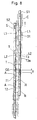
- Figs. 7 and 8 show a second embodiment which is advantageously applicable when the diametrical difference between two adjacent sprockets is relatively small.
- a multiple sprocket assembly S according to the second embodiment includes a diametrically smaller sprocket S1 and a diametrically larger sprocket S2, but the diametrical difference between these two sprockets is relatively small.
- the larger sprocket S2 of the second embodiment is substantially identical to that of the first embodiment except for minor dimensional differences. Thus, the specific configuration of the larger sprocket is not described here to avoid duplicated explanation.
- the chain C engaging with the smaller sprocket S1 starts disengaging therefrom at a particular furrow center O1 and takes a shifting path SP toward a particular furrow center O2 of the larger sprocket S2.
- the chain shifting path SP is bent instead of straight.
- a particular tooth T3 (hereafter referred to as "chain bending tooth") of the smaller sprocket S1 is made to have an guiding face T3a.
- the chain bending tooth T3 is a second tooth following the particular furrow center O1 of the smaller sprocket and located between the two particular furrow centers O1, O2.
- a chain link L2 (or L1) of the chain rides on the guiding face T3a of the chain bending tooth T3 and is lifted thereby.
- the guiding face T3a may be made to have a shape coinciding with the radially inner marginal edge of the lifted link.
- the guiding face T3a may be otherwise shaped as long as the chain link is conveniently lifted up and supported.
- the chain C takes the bent shifting bath SP when shifting from the smaller sprocket S1 to the larger sprocket S2.
- the bent shifting path is longer than a straight shifting path, and the chain can deform laterally (i.e., incline laterally) in such an elongated path for shifting to the larger sprocket.
- the stress or strain produced in the shifting portion of the chain is correspondingly reduced to enable smooth chain shifting.
- This feature is particularly advantageous when the diametrical difference between the two sprockets S1, S2 is relatively small to provide the tendency of shortening the chain shifting path.
Landscapes
- Engineering & Computer Science (AREA)
- Chemical & Material Sciences (AREA)
- Combustion & Propulsion (AREA)
- Transportation (AREA)
- Mechanical Engineering (AREA)
- Gears, Cams (AREA)
- Transmissions By Endless Flexible Members (AREA)
Claims (6)
- Zusammenbau eines mehrstufigen Kettenrades für ein Fahrrad mit zumindest zwei nebeneinander liegenden Kettenrädern, welche ein im Durchmesser größeres Kettenrad (S2) und ein im Durchmesser kleineres Kettenrad (S1) aufweisen, wobei jedes Kettenrad Zähne (T, T1, T2, T3) alternierend mit Zahnzwischenraumen (Tf) aufweist, wobei jeder Zahn ein Scheitel hat, wobei jeder Zahn weiterhin eine Vorderkante (Ta, Ta') und eine Hinterkante (Tb) bezüglich einer Vorwärtsdrehrichtung des Kettenradzusammenbaus hat, wobei eine Kette (C) einen Schaltweg einnimmt, der sich von einem ausgewählten Zahnzwischenraum (O1) des kleinerern Kettenrades zu einem ausgewählten Zahnzwischenraum (O2) des größeren Kettenrades zur Zeit des Schaltens von dem kleineren Kettenrad auf das größere Kettenrad erstreckt,
wobei zumindest zwei Zähne (T1, T2) des größeren Kettenrades (S2), die dem ausgewählten Zahnzwischenraum (O2) unmittelbar folgen, seitlich zum kleineren Kettenrad hin versetzt sind;
wobei eine Seitenoberfläche des größeren Kettenrades, die dem kleineren Kettenrad näher gelegen ist, mit einem Ausschnitt (B) zum Reduzieren einer Interferenz zwischen dem größeren Kettenrad und der sich entlang des Schaltweges bewegenden Ketten ausgebildet ist;
und wobei zumindest der Zahn des größeren Kettenrades (T), der dem ausgewählten Zahnzwischenraum (O2) vorhergeht, umfangsmäßig symmetrisch ist,
dadurch gekennzeichnet, daß
jeder der seitlich versetzten Zähne umfangsmäßig asymmetrisch ist, wobei die Vorderkanten (Tb) in Positionen entsprechend denen der symmetrischen Zähne gelegen sind, wobei die Vorderkanten (Ta, Ta') mit einer Lagerfläche (A, A'), die nach hinten bezüglich der eines entsprechenden symmetrischen Zahns versetzt ist, zum Haltern und Berühren der sich verstellenden Kette neben einer Kettenverbindung (R) in einem angehobenen Zustand versehen sind. - Kettenradzusammenbau nach Anspruch 1, dadurch gekennzeichnet, daß die Lagerfläche (A) jedes asymmetrischen Zahns (T1, T2) durch Abrunden ihres Scheitels zu ihrer Vorderkante (Ta) hin ausgebildet ist.
- Kettenradzusammenbau nach Anspruch 1, dadurch gekennzeichnet, daß die Vorderkante (Ta') jedes asymmetrischen Zahns (T1, T2) im ganzen nach hinten versetzt ist.
- Kettenradzusammenbau nach Anspruch 1, dadurch gekennzeichnet, daß zumindest zwei Zähne (T) des größeren Kettenrades (S2), die dem ausgewählten Zahnzwischenraum (O2) des größeren Kettenrades bezüglich der Drehrichtung unmittelbar vorausgehen, seitlich von dem kleineren Kettenrad S1 wegversetzt sind.
- Kettenradzusammenbau nach Anspruch 1, dadurch gekennzeichnet, daß der Durchmesserunterschied zwischen dem kleineren und dem größeren Kettenrad (S1, S2) derart ist, daß der Kettenschaltweg geradlinig wird.
- Kettenradzusammenbau nach Anspruch 1, dadurch gekennzeichnet, daß der Durchmesserunterschied zwischen dem kleineren und dem größeren Kettenrad (S1, S2) derart ist, daß der Kettenschaltweg mit einem Kettenbiegezahn (T3) des kleineren Kettenrades, der einem weiteren Zahn des kleineren Kettenrades folgt, der unmittelbar hinter dem ausgewählten Zahnzwischenraum (O1) des kleineren Kettenrades gelegen ist, interferiert, wobei der Kettenbiegezahn eine Führungsfläche (T3a) ausweist, die die Kette beim Schalten auf das größere Kettenrad lagert und biegt.
Applications Claiming Priority (4)
| Application Number | Priority Date | Filing Date | Title |
|---|---|---|---|
| JP249773/90 | 1990-09-18 | ||
| JP24977390A JPH04126692A (ja) | 1990-09-18 | 1990-09-18 | 自転車用多段スプロケット装置 |
| JP25373890A JPH04129894A (ja) | 1990-09-20 | 1990-09-20 | 自転車用多段スプロケット装置 |
| JP253738/90 | 1990-09-20 |
Publications (2)
| Publication Number | Publication Date |
|---|---|
| EP0479032A1 EP0479032A1 (de) | 1992-04-08 |
| EP0479032B1 true EP0479032B1 (de) | 1997-03-05 |
Family
ID=26539477
Family Applications (1)
| Application Number | Title | Priority Date | Filing Date |
|---|---|---|---|
| EP91115738A Expired - Lifetime EP0479032B1 (de) | 1990-09-18 | 1991-09-17 | Zusammenbau eines mehrstufigen Kettenrades für ein Fahrrad |
Country Status (3)
| Country | Link |
|---|---|
| US (1) | US5162022A (de) |
| EP (1) | EP0479032B1 (de) |
| DE (1) | DE69124901T2 (de) |
Cited By (1)
| Publication number | Priority date | Publication date | Assignee | Title |
|---|---|---|---|---|
| US8226511B2 (en) | 2005-01-08 | 2012-07-24 | Shimano, Inc. | Bicycle sprocket tooth with a shift assist radius greater than a reference tooth radius |
Families Citing this family (30)
| Publication number | Priority date | Publication date | Assignee | Title |
|---|---|---|---|---|
| IT1270417B (it) * | 1993-06-03 | 1997-05-05 | Campagnolo Srl | Gruppo pignoni per biciclette |
| EP0671316B1 (de) * | 1994-03-10 | 2000-01-12 | Industrial Technology Research Institute | Trimmverfahren für zwei Zahnräder und daraus hergestellte Struktur eines mehrstufigen Kettenrades für ein Fahrrad |
| JP3509214B2 (ja) * | 1994-09-09 | 2004-03-22 | 株式会社シマノ | 自転車用チェーンホイール |
| DE4445035C1 (de) * | 1994-12-16 | 1996-06-05 | Fichtel & Sachs Ag | Kettenschaltung |
| US5569107A (en) * | 1995-05-31 | 1996-10-29 | Falcon Industrial Co., Ltd. | Multi-step bicycle transmission sprocket assembly |
| US5690570A (en) * | 1995-09-26 | 1997-11-25 | Industrial Development Bureau | Multistage sprocket assembly for a bicycle |
| US5876295A (en) * | 1996-01-23 | 1999-03-02 | Cloyes Gear And Products, Inc. | Roller chain drive system having improved noise characteristics |
| DE19606667C2 (de) * | 1996-02-23 | 1999-10-14 | Sram De Gmbh | Kettenschaltung für Fahrräder |
| US5921878A (en) * | 1996-07-03 | 1999-07-13 | Cloyes Gear And Products, Inc. | Roller chain drive system having improved noise characteristics |
| US5921879A (en) * | 1996-07-25 | 1999-07-13 | Cloyes Gear And Products, Inc. | Random engagement roller chain sprocket with staged meshing and flank relief to provide improved noise characteristics |
| BR9710575A (pt) * | 1996-07-25 | 1999-09-14 | Cloyes Gear & Products Inc | Roda dentada de corrente de rolos, de engate aleatório, com caracterìsticas de ruìdo aperfeiçoadas. |
| US6090003A (en) * | 1996-07-25 | 2000-07-18 | Cloyes Gear & Products, Inc. | Random engagement roller chain sprocket having improved noise characteristics |
| US6761657B2 (en) | 1996-12-19 | 2004-07-13 | Cloyes Gear And Products, Inc. | Roller chain sprocket with added chordal pitch reduction |
| US7416500B2 (en) * | 1996-12-19 | 2008-08-26 | Cloyes Gear And Products, Inc. | Random engagement roller chain sprocket and timing chain system including same |
| TW331290U (en) * | 1997-08-01 | 1998-05-01 | Tracer Company Ltd | Improved structure of a chain wheel assembly of a bicycle |
| US6045472A (en) * | 1997-12-30 | 2000-04-04 | National Science Council | Integrated up-and downshifting configuration of a multistage sprocket assembly for a bicycle |
| US6558945B1 (en) * | 1999-03-08 | 2003-05-06 | Aclara Biosciences, Inc. | Method and device for rapid color detection |
| DE10017723A1 (de) | 2000-04-11 | 2001-10-18 | Schill Maja Masch | Scherbeneismaschine |
| DE10119590A1 (de) * | 2001-04-21 | 2002-10-24 | Sram De Gmbh | Kettenrad für Rollenketten |
| US8096908B2 (en) * | 2004-12-14 | 2012-01-17 | Shimano, Inc. | Bicycle sprocket with a laterally projecting gear change tooth |
| DE102006010498A1 (de) * | 2006-03-07 | 2007-09-13 | Sram Deutschland Gmbh | Mehrfachkettenradeinheit und Kettenschaltung, insbesondere für Fahrräder |
| EP2108579A1 (de) * | 2008-04-10 | 2009-10-14 | CAMPAGNOLO S.r.l. | Zahnrad und Gruppe von Zahnrädern für ein Fahrrad-Übertragungssystem |
| US9327792B2 (en) | 2011-01-28 | 2016-05-03 | Paha Designs, Llc | Gear transmission and derailleur system |
| US10207772B2 (en) | 2011-01-28 | 2019-02-19 | Paha Designs, Llc | Gear transmission and derailleur system |
| US9033833B2 (en) | 2011-01-28 | 2015-05-19 | Paha Designs, Llc | Gear transmission and derailleur system |
| US9725132B2 (en) * | 2014-03-26 | 2017-08-08 | Shimano Inc. | Bicycle crank assembly |
| DE102015219522B4 (de) * | 2014-10-14 | 2025-07-24 | Sram Deutschland Gmbh | Mehrfach-Kettenradanordnung für eine Hinterradnabe |
| US20160208903A1 (en) * | 2015-03-25 | 2016-07-21 | Wick Werks, LLC | Chainrings with Alternating Tooth Thickness Offset |
| US10407127B2 (en) * | 2016-11-24 | 2019-09-10 | Shimano Inc. | Bicycle sprocket |
| DE102021209407A1 (de) | 2021-08-26 | 2023-03-02 | Shimano Inc. | Ein hinteres kettenrad und eine hintere kettenradanordnung |
Family Cites Families (7)
| Publication number | Priority date | Publication date | Assignee | Title |
|---|---|---|---|---|
| US4268259A (en) * | 1977-08-25 | 1981-05-19 | Shimano Industrial Company Limited | Multi-speed sprockets for a bicycle and the like |
| JPS566698U (de) * | 1979-06-28 | 1981-01-21 | ||
| US4519791A (en) * | 1982-09-03 | 1985-05-28 | Shimano Industrial Company Limited | Sprocket for a bicycle |
| DE313345T1 (de) * | 1987-10-21 | 1990-05-03 | Zusammenbau eines mehrstufigen kettenrades fuer ein fahrrad. | |
| JPH02127185A (ja) * | 1988-11-07 | 1990-05-15 | Shimano Ind Co Ltd | 自転車用多段スプロケット装置 |
| JP3140026B2 (ja) * | 1990-02-28 | 2001-03-05 | 株式会社シマノ | 自転車用多段スプロケット装置 |
| JP3111072B2 (ja) * | 1990-02-28 | 2000-11-20 | 株式会社シマノ | 自転車用多段スプロケット装置 |
-
1991
- 1991-09-13 US US07/759,906 patent/US5162022A/en not_active Expired - Lifetime
- 1991-09-17 EP EP91115738A patent/EP0479032B1/de not_active Expired - Lifetime
- 1991-09-17 DE DE69124901T patent/DE69124901T2/de not_active Expired - Fee Related
Cited By (1)
| Publication number | Priority date | Publication date | Assignee | Title |
|---|---|---|---|---|
| US8226511B2 (en) | 2005-01-08 | 2012-07-24 | Shimano, Inc. | Bicycle sprocket tooth with a shift assist radius greater than a reference tooth radius |
Also Published As
| Publication number | Publication date |
|---|---|
| US5162022A (en) | 1992-11-10 |
| EP0479032A1 (de) | 1992-04-08 |
| DE69124901D1 (de) | 1997-04-10 |
| DE69124901T2 (de) | 1997-06-19 |
Similar Documents
| Publication | Publication Date | Title |
|---|---|---|
| US5162022A (en) | Multiple sprocket assembly for bicycle | |
| US5458543A (en) | Bicycle multiple sprocket assembly | |
| US5192249A (en) | Multi-stage sprocket assembly for bicycle | |
| US11866126B2 (en) | Multi-sprocket assembly for a bicycle | |
| EP0510361B1 (de) | Zusammenbau eines mehrstufigen Kettenrades für ein Fahrrad | |
| EP0538780B1 (de) | Tragelement für eine Fahrradkettenschaltung | |
| US4889521A (en) | Multistage sprocket assembly for a bicycle | |
| EP0505809B1 (de) | Zusammenbau eines mehrstufigen Kettenrades für ein Fahrrad | |
| US5133695A (en) | Bicycle multiple chainwheel | |
| US4348200A (en) | Multi-speed sprocket assembly for a bicycle | |
| JP2901268B2 (ja) | 多段ギヤ装置 | |
| US8096908B2 (en) | Bicycle sprocket with a laterally projecting gear change tooth | |
| EP1679255B1 (de) | Zahn eines Fahrradzahnrads | |
| US7942771B2 (en) | Bicycle sprocket apparatus with a shift inhibiting structure | |
| US5073151A (en) | Multi-speed sprocket assembly for bicycle | |
| US5876296A (en) | Gear shifting sprocket set for bicycle chain wheel | |
| US5437582A (en) | Sprocket assembly for bicycles | |
| EP0386685B1 (de) | Mehrfach-Kettenrad für ein Fahrrad | |
| EP0417696B1 (de) | Kettenradsatz für Fahrrad | |
| EP0444556B1 (de) | Zusammenbau eines mehrstufigen Kettenrades für ein Fahrrad | |
| US20140013900A1 (en) | Bicycle front sprocket | |
| JP2006008111A (ja) | 自転車スプロケット用シフト補助突起 | |
| JP2004090914A (ja) | リアスプロケット組立体のためのトップスプロケット、及び自転車のためのリアスプロケット組立体 | |
| EP0130984A1 (de) | Stufenweise änderbare übersetzung für getriebe. | |
| JPH04129894A (ja) | 自転車用多段スプロケット装置 |
Legal Events
| Date | Code | Title | Description |
|---|---|---|---|
| PUAI | Public reference made under article 153(3) epc to a published international application that has entered the european phase |
Free format text: ORIGINAL CODE: 0009012 |
|
| AK | Designated contracting states |
Kind code of ref document: A1 Designated state(s): DE FR IT |
|
| 17P | Request for examination filed |
Effective date: 19920327 |
|
| 17Q | First examination report despatched |
Effective date: 19921126 |
|
| GRAG | Despatch of communication of intention to grant |
Free format text: ORIGINAL CODE: EPIDOS AGRA |
|
| RAP1 | Party data changed (applicant data changed or rights of an application transferred) |
Owner name: SAKAE CO., LTD. |
|
| GRAH | Despatch of communication of intention to grant a patent |
Free format text: ORIGINAL CODE: EPIDOS IGRA |
|
| GRAH | Despatch of communication of intention to grant a patent |
Free format text: ORIGINAL CODE: EPIDOS IGRA |
|
| GRAA | (expected) grant |
Free format text: ORIGINAL CODE: 0009210 |
|
| AK | Designated contracting states |
Kind code of ref document: B1 Designated state(s): DE FR IT |
|
| PG25 | Lapsed in a contracting state [announced via postgrant information from national office to epo] |
Ref country code: IT Free format text: LAPSE BECAUSE OF FAILURE TO SUBMIT A TRANSLATION OF THE DESCRIPTION OR TO PAY THE FEE WITHIN THE PRE;WARNING: LAPSES OF ITALIAN PATENTS WITH EFFECTIVE DATE BEFORE 2007 MAY HAVE OCCURRED AT ANY TIME BEFORE 2007. THE CORRECT EFFECTIVE DATE MAY BE DIFFERENT FROM THE ONE RECORDED.SCRIBED TIME-LIMIT Effective date: 19970305 |
|
| REF | Corresponds to: |
Ref document number: 69124901 Country of ref document: DE Date of ref document: 19970410 |
|
| ET | Fr: translation filed | ||
| PLBE | No opposition filed within time limit |
Free format text: ORIGINAL CODE: 0009261 |
|
| STAA | Information on the status of an ep patent application or granted ep patent |
Free format text: STATUS: NO OPPOSITION FILED WITHIN TIME LIMIT |
|
| 26N | No opposition filed | ||
| PGFP | Annual fee paid to national office [announced via postgrant information from national office to epo] |
Ref country code: DE Payment date: 20020827 Year of fee payment: 12 |
|
| PGFP | Annual fee paid to national office [announced via postgrant information from national office to epo] |
Ref country code: FR Payment date: 20020830 Year of fee payment: 12 |
|
| PG25 | Lapsed in a contracting state [announced via postgrant information from national office to epo] |
Ref country code: DE Free format text: LAPSE BECAUSE OF NON-PAYMENT OF DUE FEES Effective date: 20040401 |
|
| PG25 | Lapsed in a contracting state [announced via postgrant information from national office to epo] |
Ref country code: FR Free format text: LAPSE BECAUSE OF NON-PAYMENT OF DUE FEES Effective date: 20040528 |
|
| REG | Reference to a national code |
Ref country code: FR Ref legal event code: ST |