EP0479038A2 - Cadre d'images pour guider les bandes de film exposé et développé - Google Patents
Cadre d'images pour guider les bandes de film exposé et développé Download PDFInfo
- Publication number
- EP0479038A2 EP0479038A2 EP91115796A EP91115796A EP0479038A2 EP 0479038 A2 EP0479038 A2 EP 0479038A2 EP 91115796 A EP91115796 A EP 91115796A EP 91115796 A EP91115796 A EP 91115796A EP 0479038 A2 EP0479038 A2 EP 0479038A2
- Authority
- EP
- European Patent Office
- Prior art keywords
- guide
- film strips
- transport
- master
- stage according
- Prior art date
- Legal status (The legal status is an assumption and is not a legal conclusion. Google has not performed a legal analysis and makes no representation as to the accuracy of the status listed.)
- Granted
Links
- 238000003384 imaging method Methods 0.000 title 1
- 238000003780 insertion Methods 0.000 claims description 5
- 230000037431 insertion Effects 0.000 claims description 5
- 230000001154 acute effect Effects 0.000 claims description 3
- 238000000034 method Methods 0.000 description 4
- 238000012545 processing Methods 0.000 description 4
- 108091006146 Channels Proteins 0.000 description 2
- 238000012937 correction Methods 0.000 description 2
- 230000004888 barrier function Effects 0.000 description 1
- 230000015572 biosynthetic process Effects 0.000 description 1
- 230000001419 dependent effect Effects 0.000 description 1
- 238000013461 design Methods 0.000 description 1
- 230000000694 effects Effects 0.000 description 1
- 238000011156 evaluation Methods 0.000 description 1
- 238000003754 machining Methods 0.000 description 1
- 239000000725 suspension Substances 0.000 description 1
Images
Classifications
-
- G—PHYSICS
- G03—PHOTOGRAPHY; CINEMATOGRAPHY; ANALOGOUS TECHNIQUES USING WAVES OTHER THAN OPTICAL WAVES; ELECTROGRAPHY; HOLOGRAPHY
- G03B—APPARATUS OR ARRANGEMENTS FOR TAKING PHOTOGRAPHS OR FOR PROJECTING OR VIEWING THEM; APPARATUS OR ARRANGEMENTS EMPLOYING ANALOGOUS TECHNIQUES USING WAVES OTHER THAN OPTICAL WAVES; ACCESSORIES THEREFOR
- G03B1/00—Film strip handling
- G03B1/18—Moving film strip by means which act on the film between the ends thereof
- G03B1/20—Acting means
- G03B1/32—Friction grippers or rollers
-
- G—PHYSICS
- G03—PHOTOGRAPHY; CINEMATOGRAPHY; ANALOGOUS TECHNIQUES USING WAVES OTHER THAN OPTICAL WAVES; ELECTROGRAPHY; HOLOGRAPHY
- G03B—APPARATUS OR ARRANGEMENTS FOR TAKING PHOTOGRAPHS OR FOR PROJECTING OR VIEWING THEM; APPARATUS OR ARRANGEMENTS EMPLOYING ANALOGOUS TECHNIQUES USING WAVES OTHER THAN OPTICAL WAVES; ACCESSORIES THEREFOR
- G03B27/00—Photographic printing apparatus
- G03B27/32—Projection printing apparatus, e.g. enlarger, copying camera
- G03B27/52—Details
- G03B27/62—Holders for the original
- G03B27/6271—Holders for the original in enlargers
- G03B27/6285—Handling strips
Definitions
- the invention is based on a master stage according to the preamble of the main claim.
- a device for copying film strips is known.
- the beginning of the film strip is inserted into a receptacle by an operator.
- the film is captured by a drive and fed into a memory via a scan station.
- the film is pulled out of the memory in the opposite direction and the individual images are fed in reverse order to a copying station.
- the film strip is ejected again via the same transport device via which it was drawn in.
- Devices of this type are often used for processing reorder orders. For each film strip that the operator inserts, they can simultaneously use the corresponding data - such as the number of images and any color correction values - received. However, in order to be able to insert the next film strip and to be able to enter the associated data into the device, the operator must wait until the previous film section has been measured, the corresponding values have been calculated and the copying process has ended. Only when the filmstrip has been ejected can the next filmstrip be inserted and its data entered.
- the object is achieved by the features described in the characterizing part of the main claim in relation to film strips and in claim 2 in relation to slides. Due to the fact that the processed film strip is ejected again at another point on the device, the operator can insert the next film strip into the device already during the machining process and enter the associated data.
- the input opening is advantageous for the film strips arranged above the discharge opening.
- the two guideways are brought together at an acute angle before the first processing station, so that a simple switch arrangement makes it possible to correctly guide the film strip to the discharge opening when it is transported back.
- This switch can be designed as a soft spring which, in its rest position, assumes a position which closes the feed channel for the film when it is transported back and thus guides it into the export channel.
- a motor which drives a pair of drive rollers in the feed chute and a pair of drive rollers in the discharge chute - for example via a belt.
- the motor can be switched in both directions.
- this drive roller is provided with a freewheel.
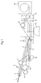
- the film section 1 provided with a tabber strip is inserted into the insertion shaft 2 of the template stage by the operator.
- a signal generator 5 This can be a microswitch or a light barrier in any way.
- the presence of the film strip is determined by the signal transmitter and a corresponding signal is sent to a control unit (not shown). If there is no corresponding signal from the transmitters 6 and 7, the drive motor 8 starts up in the direction of the arrow A.
- the transmitter 7 can also be saved and the signal can be taken directly from the scanner 13.
- the drive roller pair 4 is driven via the belt 10, which then pulls in the film strip 1.
- the spring 9 is designed so soft that it can be pressed down by the film strip striking it and thus guides the film to the second pair of drive rollers 11.
- the drive motor 12 starts in the direction of arrow C.
- the filmstrip is now through the Transported scan station 13, in which the transparency values are measured.
- the film strip is then pushed into the memory 15 via the pair of transport rollers 14.
- the motor 12 switches over and starts up in the direction of the arrow D.
- the film is now pulled out of the memory 15 and transported via the copying station 16. With the help of the position and transparency data determined in the scan station 13, the prints requested by the customer are exposed here.
- the motor 8 starts in the direction of the arrow B.
- the film is captured by the pair of drive rollers 18 and ejected.
- a freewheel is provided in the direction of arrow B in one operating mode of the motor 8.
- the motor 8 switches again in the direction of the arrow A, so that the next film strip can be drawn in.
- a freewheel is also provided here, which is opposite to the freewheel of the drive roller pair 4 in the direction of rotation the arrow A of the motor 8 acts.
- the circuit of the drive 8 is dependent not only on the signal generator 5, but also on the two signal generators 6 and 7, it is ensured that the new film strip is only drawn in when the previous film strip has been finished and through the ejection chute 17 again was expelled.
- the operator has the possibility, as soon as a film strip has been drawn in, to insert the next one into the insertion shaft 2 without it being immediately picked up by the drive roller pair 4.
- the operator can already have the data for the next film strip - such as e.g. B. Enter the number of prints and any color correction values into the device.
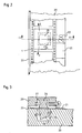
- the formation of the drive roller pairs 4, 11 and 14 is described in more detail in FIGS. 2 and 3.
- the film 1 with the tabber strip 21 connected to it lies on the base 20.
- the slide rail 23, which is formed in one piece with the base 20, serves as a stop.
- Fields 22 are provided on the tabber strip 21, the width of which does not matter, on which the customer can note which pictures and how many he wants.
- a recess 24 is provided in the lower part 20, in which a frustoconical roller 25 is mounted.
- the roller 25 is installed so that the film 1 lies flat on its outer surface.
- the cylindrical roller 26 serves as the drive roller. It is mounted in a recess 27 in the upper part 28.
- the film 1 should be approximately always applied with the same force between the two rolls 25 and 26. This can be achieved either by an elastic connection between the upper part 28 and the lower part 23 or by a spring suspension of one of the two rollers 25, 26.
- the film 1 tends to move either in the direction of arrow E or in the direction of arrow F, depending on the direction of rotation of the pair of drive rollers. Both arrows have a component in the direction of the slide rail 23. This means that the film 1 always endeavors to stay in contact with the slide rail 23 serving as a stop, regardless of whether it is transported forward or backward.
- two frustoconical rollers could also be used.
- the drive roller would also have to be mounted at an angle, which would lead to additional design effort.
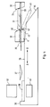
- the slide 31 is inserted into the receiving opening 46 of the slide 32 by the operator thereby comes to rest on a first guide plate 33.
- the edge 34 is correspondingly inclined. If the slide 32 moves in the direction of the arrow A, the slide reaches the inclined surface 35 of the first guide plate 33 and is inclined somewhat in its direction of movement in the direction of a second guide plate 36.
- the guide element 37 finally guides the slide onto the second guide plate 36, where it is then pushed on up to the stop 38.
- the slide is processed by the scanning or copying device 40. In this position, the slide is centered by known and not shown means.
- the extension 41 reaches behind the slide in position 39 and pushes it in the same direction.
- the edge 42 is inclined in order to hold the slide on its base.
- the slide is then conveyed into the discharge chute 44 via the inclined surface 43 of the second guide plate 36. In this position the slide is labeled 45. Since the receiving opening 46 of the slider 32 is already empty when the starting position is reached, the operator can insert the next slide immediately without having to remove the already processed one.
Landscapes
- Physics & Mathematics (AREA)
- General Physics & Mathematics (AREA)
- Projection-Type Copiers In General (AREA)
Applications Claiming Priority (2)
| Application Number | Priority Date | Filing Date | Title |
|---|---|---|---|
| DE4031025A DE4031025A1 (de) | 1990-10-01 | 1990-10-01 | Vorlagenbuehne zur fuehrung von belichteten und entwickelten filmstreifen |
| DE4031025 | 1990-10-01 |
Publications (3)
| Publication Number | Publication Date |
|---|---|
| EP0479038A2 true EP0479038A2 (fr) | 1992-04-08 |
| EP0479038A3 EP0479038A3 (en) | 1993-02-24 |
| EP0479038B1 EP0479038B1 (fr) | 1996-01-17 |
Family
ID=6415362
Family Applications (1)
| Application Number | Title | Priority Date | Filing Date |
|---|---|---|---|
| EP91115796A Expired - Lifetime EP0479038B1 (fr) | 1990-10-01 | 1991-09-18 | Cadre d'images pour guider les bandes de film exposé et développé |
Country Status (4)
| Country | Link |
|---|---|
| US (1) | US5162840A (fr) |
| EP (1) | EP0479038B1 (fr) |
| JP (1) | JP2579085B2 (fr) |
| DE (2) | DE4031025A1 (fr) |
Families Citing this family (5)
| Publication number | Priority date | Publication date | Assignee | Title |
|---|---|---|---|---|
| DE4229520C1 (de) * | 1992-09-04 | 1993-11-04 | Agfa Gevaert Ag | Vorrichtung zum speichern von fotografischen filmstreifen |
| US5461492A (en) * | 1994-02-16 | 1995-10-24 | Eastman Kodak Company | Film scanner with in-line dual scanning gates |
| US5465134A (en) * | 1994-02-16 | 1995-11-07 | Eastman Kodak Company | Passive film take-up chamber |
| DE9419287U1 (de) * | 1994-12-02 | 1995-03-16 | SYMICRON GmbH SOFTWARE-ENGINEERING, 40880 Ratingen | Vorrichtung zum Digitalisieren von auf einem Abschnitt eines Filmstreifens vorhandenen Bildern |
| US5730378A (en) * | 1995-08-25 | 1998-03-24 | Eastman Kodak Company | Filmstrip take-up chamber |
Family Cites Families (11)
| Publication number | Priority date | Publication date | Assignee | Title |
|---|---|---|---|---|
| DE1965244C3 (de) * | 1969-12-29 | 1978-03-09 | Agfa-Gevaert Ag, 5090 Leverkusen | Fotografisches Kopiergerät |
| DE2551799C2 (de) * | 1975-11-18 | 1986-05-28 | Agfa-Gevaert Ag, 5090 Leverkusen | Verfahren und Vorrichtung zum Bewerten der Dichte und Farbe von Kopiervorlagen |
| NL7701431A (nl) * | 1976-03-08 | 1977-09-12 | Xerox Corp | Werkwijze voor het omkeren van de bewegings- richting van een blad. |
| JPS5878142A (ja) * | 1981-11-05 | 1983-05-11 | Fuji Xerox Co Ltd | マイクロフィルム保持シート位置合せ制御装置 |
| DE3437222A1 (de) * | 1984-10-10 | 1986-04-17 | Agfa-Gevaert Ag, 5090 Leverkusen | Verfahren und vorrichtung zum kopieren fotografischer kopiervorlagen |
| CH670900A5 (fr) * | 1986-08-29 | 1989-07-14 | Germann & Gsell Ag | |
| JPH06103377B2 (ja) * | 1986-10-15 | 1994-12-14 | 富士写真フイルム株式会社 | 写真焼付方法 |
| DE3737788C2 (de) * | 1987-11-06 | 1997-10-09 | Agfa Gevaert Ag | Vorrichtung zum automatischen Wechsel der Filmstreifen in einem Rollenkopiergerät |
| JPH02198947A (ja) * | 1989-01-26 | 1990-08-07 | Toshiba Corp | 画像形成装置 |
| JPH02214837A (ja) * | 1989-02-15 | 1990-08-27 | Konica Corp | 短尺原画フィルムの画像駒検出装置 |
| FR2656433B1 (fr) * | 1989-12-22 | 1992-05-07 | Genieis Jean | Dispositifs pour alimenter automatiquement un projecteur d'images. |
-
1990
- 1990-10-01 DE DE4031025A patent/DE4031025A1/de not_active Withdrawn
-
1991
- 1991-09-13 US US07/759,886 patent/US5162840A/en not_active Expired - Lifetime
- 1991-09-18 DE DE59107279T patent/DE59107279D1/de not_active Expired - Fee Related
- 1991-09-18 EP EP91115796A patent/EP0479038B1/fr not_active Expired - Lifetime
- 1991-09-25 JP JP3243900A patent/JP2579085B2/ja not_active Expired - Fee Related
Also Published As
| Publication number | Publication date |
|---|---|
| EP0479038B1 (fr) | 1996-01-17 |
| EP0479038A3 (en) | 1993-02-24 |
| JP2579085B2 (ja) | 1997-02-05 |
| US5162840A (en) | 1992-11-10 |
| DE59107279D1 (de) | 1996-02-29 |
| JPH04234747A (ja) | 1992-08-24 |
| DE4031025A1 (de) | 1992-04-02 |
Similar Documents
| Publication | Publication Date | Title |
|---|---|---|
| DE2729059C2 (de) | Anordnung zum Verarbeiten von zwei zusammengehörigen Dokumenten | |
| EP0217213B1 (fr) | Cassette de film à rayons X chargeable et déchargeable automatiquement et appareil de chargement et de déchargement de film à rayons X approprié | |
| DE3122583C2 (de) | Vorrichtung zum Be- und Entladen von Röntgenfilmkassetten | |
| DE19723875B4 (de) | Vorlagenzuführer für Bilderzeugungsgeräte und diesen verwendendes Bilderzeugungsgerät | |
| DE60201697T2 (de) | Automatischer Dokumentzuführer und hiermit versehener Bilderzeugungsapparat | |
| DE2617479B2 (de) | Papiertransporteinrichtung in einem kopiergeraet | |
| DE2908398A1 (de) | Dokumenten-zufuehrvorrichtung fuer kopiergeraete | |
| DE1902112C3 (de) | Fördervorrichtung für eine Kopiermaschine | |
| DE2936272A1 (de) | Kopierwiederholungssystem | |
| DE2522664A1 (de) | Steuermechanismus fuer die zufuehrung von boegen, blaettern oder karten | |
| DE3104659A1 (de) | Faksimileeinrichtung | |
| DE3546069A1 (de) | Automatisches duplex-kopiergeraet | |
| DE60006237T2 (de) | Ein Dokumentenzuführgerät für zweiseitiges Kopieren mit einer kürzeren Länge als das zu kopierende Dokument | |
| DE3036648A1 (de) | Blattverteilungsverfahren | |
| DE3408481C2 (de) | Automatische Vorlagenzuführeinrichtung | |
| DE4434079C2 (de) | Vorrichtung zum Detektieren der Lage von Papierblättern | |
| EP0177703A1 (fr) | Méthode et dispositif pour la détermination automatique des bords d'images d'un film positif | |
| DE69420618T2 (de) | Gerät zur Anordnung von lichtempflindlichem Material | |
| EP0479038B1 (fr) | Cadre d'images pour guider les bandes de film exposé et développé | |
| EP0576769B1 (fr) | Méthode et dispositif pour le traitement de sections d'un ruban photographique | |
| DE3817587A1 (de) | Blattfoerdervorrichtung | |
| DE19824092A1 (de) | Postprozessor | |
| DE3122586A1 (de) | Vorrichtung zum entladen von roentgenfilm-kassetten | |
| DE3104670A1 (de) | Vorrichtung zum trennen von einzelnen zu einem stapel zusammengefassten blaettern | |
| EP0570651A1 (fr) | Appareil à copier pour copier des originaux sur du matériau en feuilles pour l'enregistrement |
Legal Events
| Date | Code | Title | Description |
|---|---|---|---|
| PUAI | Public reference made under article 153(3) epc to a published international application that has entered the european phase |
Free format text: ORIGINAL CODE: 0009012 |
|
| AK | Designated contracting states |
Kind code of ref document: A2 Designated state(s): CH DE FR GB LI |
|
| PUAL | Search report despatched |
Free format text: ORIGINAL CODE: 0009013 |
|
| AK | Designated contracting states |
Kind code of ref document: A3 Designated state(s): CH DE FR GB LI |
|
| 17P | Request for examination filed |
Effective date: 19930122 |
|
| 17Q | First examination report despatched |
Effective date: 19950222 |
|
| GRAA | (expected) grant |
Free format text: ORIGINAL CODE: 0009210 |
|
| AK | Designated contracting states |
Kind code of ref document: B1 Designated state(s): CH DE FR GB LI |
|
| GBT | Gb: translation of ep patent filed (gb section 77(6)(a)/1977) |
Effective date: 19960119 |
|
| REF | Corresponds to: |
Ref document number: 59107279 Country of ref document: DE Date of ref document: 19960229 |
|
| REG | Reference to a national code |
Ref country code: CH Ref legal event code: NV Representative=s name: E. BLUM & CO. PATENTANWAELTE |
|
| ET | Fr: translation filed | ||
| PLBE | No opposition filed within time limit |
Free format text: ORIGINAL CODE: 0009261 |
|
| STAA | Information on the status of an ep patent application or granted ep patent |
Free format text: STATUS: NO OPPOSITION FILED WITHIN TIME LIMIT |
|
| 26N | No opposition filed | ||
| REG | Reference to a national code |
Ref country code: GB Ref legal event code: IF02 |
|
| REG | Reference to a national code |
Ref country code: GB Ref legal event code: 746 Effective date: 20040427 |
|
| REG | Reference to a national code |
Ref country code: FR Ref legal event code: D6 |
|
| PGFP | Annual fee paid to national office [announced via postgrant information from national office to epo] |
Ref country code: DE Payment date: 20040927 Year of fee payment: 14 |
|
| PGFP | Annual fee paid to national office [announced via postgrant information from national office to epo] |
Ref country code: CH Payment date: 20041104 Year of fee payment: 14 |
|
| PGFP | Annual fee paid to national office [announced via postgrant information from national office to epo] |
Ref country code: FR Payment date: 20050927 Year of fee payment: 15 |
|
| PG25 | Lapsed in a contracting state [announced via postgrant information from national office to epo] |
Ref country code: CH Free format text: LAPSE BECAUSE OF NON-PAYMENT OF DUE FEES Effective date: 20050930 Ref country code: LI Free format text: LAPSE BECAUSE OF NON-PAYMENT OF DUE FEES Effective date: 20050930 |
|
| PGFP | Annual fee paid to national office [announced via postgrant information from national office to epo] |
Ref country code: GB Payment date: 20051010 Year of fee payment: 15 |
|
| REG | Reference to a national code |
Ref country code: CH Ref legal event code: PL |
|
| GBPC | Gb: european patent ceased through non-payment of renewal fee |
Effective date: 20060918 |
|
| REG | Reference to a national code |
Ref country code: FR Ref legal event code: ST Effective date: 20070531 |
|
| PG25 | Lapsed in a contracting state [announced via postgrant information from national office to epo] |
Ref country code: GB Free format text: LAPSE BECAUSE OF NON-PAYMENT OF DUE FEES Effective date: 20060918 |
|
| PG25 | Lapsed in a contracting state [announced via postgrant information from national office to epo] |
Ref country code: FR Free format text: LAPSE BECAUSE OF NON-PAYMENT OF DUE FEES Effective date: 20061002 |
|
| PG25 | Lapsed in a contracting state [announced via postgrant information from national office to epo] |
Ref country code: DE Free format text: LAPSE BECAUSE OF NON-PAYMENT OF DUE FEES Effective date: 20060401 |