EP0479220A2 - Procédé et dispositif pour transporter et travailler des matières en forme de barre - Google Patents
Procédé et dispositif pour transporter et travailler des matières en forme de barre Download PDFInfo
- Publication number
- EP0479220A2 EP0479220A2 EP91116732A EP91116732A EP0479220A2 EP 0479220 A2 EP0479220 A2 EP 0479220A2 EP 91116732 A EP91116732 A EP 91116732A EP 91116732 A EP91116732 A EP 91116732A EP 0479220 A2 EP0479220 A2 EP 0479220A2
- Authority
- EP
- European Patent Office
- Prior art keywords
- bending
- conveying
- bent
- materials
- shaped
- Prior art date
- Legal status (The legal status is an assumption and is not a legal conclusion. Google has not performed a legal analysis and makes no representation as to the accuracy of the status listed.)
- Withdrawn
Links
Images




Classifications
-
- B—PERFORMING OPERATIONS; TRANSPORTING
- B21—MECHANICAL METAL-WORKING WITHOUT ESSENTIALLY REMOVING MATERIAL; PUNCHING METAL
- B21D—WORKING OR PROCESSING OF SHEET METAL OR METAL TUBES, RODS OR PROFILES WITHOUT ESSENTIALLY REMOVING MATERIAL; PUNCHING METAL
- B21D43/00—Feeding, positioning or storing devices combined with, or arranged in, or specially adapted for use in connection with, apparatus for working or processing sheet metal, metal tubes or metal profiles; Associations therewith of cutting devices
- B21D43/006—Feeding elongated articles, such as tubes, bars, or profiles
-
- B—PERFORMING OPERATIONS; TRANSPORTING
- B21—MECHANICAL METAL-WORKING WITHOUT ESSENTIALLY REMOVING MATERIAL; PUNCHING METAL
- B21D—WORKING OR PROCESSING OF SHEET METAL OR METAL TUBES, RODS OR PROFILES WITHOUT ESSENTIALLY REMOVING MATERIAL; PUNCHING METAL
- B21D11/00—Bending not restricted to forms of material mentioned in only one of groups B21D5/00, B21D7/00, B21D9/00; Bending not provided for in groups B21D5/00 - B21D9/00; Twisting
- B21D11/10—Bending specially adapted to produce specific articles, e.g. leaf springs
- B21D11/12—Bending specially adapted to produce specific articles, e.g. leaf springs the articles being reinforcements for concrete
Definitions
- the invention relates to a method for conveying and processing, such as bending rod-shaped materials, such as wire or strip-shaped materials unwound and directed from coils, with a conveying device for the rod-shaped material to be fed to a device, such as a bending device, which preferably has two displaceable at least one each a bending roller and a bending tool comprising bending tool existing around this rotatable driving roller.
- the invention relates to a device for conveying and processing such as bending rod-shaped materials, such as coil-shaped and straightened wire or strip-shaped materials, with a conveying device for the rod-shaped material to be fed to a device such as a bending device, which preferably has two movable at least one comprises a bending slide and a bending slide comprising an existing bending tool about this rotatable driving roller.
- a bending device is known, by means of which rod-shaped materials can be bent into desired shapes.
- the bending slides are designed to be movable. In order to be able to bend the material either clockwise or counterclockwise, the material must be folded over.
- Bow bending machines are also known, in which the driving roller can be removed from the bending plane in order to allow adjustment in relation to the material to be bent, so that it can be bent clockwise or counterclockwise to the desired extent.
- Bending mandrels are arranged stationarily with the driving roller, on which the material to be bent can be supported depending on the direction of bending.
- the object is essentially achieved in accordance with the method in that the rod-shaped material to be bent is conveyed, buffered in units, in a plane running parallel to the conveying direction, and is introduced one above the other into the respective bending tool.
- the buffer conveyor has at least two, alternately guided around upper and lower deflection rollers, endless belts or chains with protrusions extending from them to form a multiplicity of material receiving areas, in each of which a desired number of cut-to-length materials in a plane running parallel to the conveying direction has one layer can be transported from an input point to an output point.
- the material to be bent which can come from a straightening or cutting machine, is therefore not stored in intermediate storage in order to be fed to a bending device if required.
- the conveying device feeding the material of the bending device also serves as a buffer, thereby ensuring that the bending device is always provided with the required amount of material without, however, the upstream machines having to be timed to the individual bending processes.
- the buffer conveyor is designed at the same time so that the materials taken up are conveyed in one layer. This means that with a horizontal conveying path of the buffer conveyor, the materials are arranged next to one another and with a vertical conveying path one above the other. This ensures that the materials to be bent are in units can be fed one above the other to the processing devices such as bending tools.
- a device for conveying and processing, such as bending rod-shaped materials, is characterized in that the material to be processed, possibly previously straightened, can be fed in sections of the desired length via a buffer conveyor to the device or an output point, and in that the buffer conveyor is an endless conveyor with a large number of material receiving areas, in each of which a desired number of cut-to-length materials is arranged in one layer in the plane running parallel to the conveying direction, the materials lying one above the other, preferably between two bending rollers, of a bending tool each being insertable.
- the buffer conveyor can preferably be a chain buffer with webs that protrude from conveyor chains and that separate the material receiving areas. Furthermore, stationary boundaries run parallel to the conveying elements, at least in the conveying path of the conveying elements, the distance between the conveying surface of the conveying elements and the stationary boundary being selected such that the materials present in the respective material receiving areas lie one above the other during vertical conveying movement.
- the buffer conveyor according to the invention preferably runs between a cutting device that cuts the material and the bending device.
- the buffer conveyor runs between an input and output point, the input point being located above upper deflection rollers arranged on an outside of the buffer conveyor, while the output point is arranged on upper deflection rollers lying on the other outside.
- the material is dispensed at a height that makes it easy to transport the material, e.g. made possible by gravity on an inclined transport plane to the bending device.
- material intake bevels with stops at the deepest points are provided above the lower deflection rollers, which - seen in the direction of transport of the materials - between the input and output points lie, which is traversed by the projections of the belt or chain in the upward direction.
- the materials are moved out of the material receiving bevels out of the movement path of the respective belt or chain and the projections.
- the materials roll or slide down on the inclines.
- the lowermost material bar or the lowest material bar bears against the respective stop until a protrusion running laterally past the material receiving bevel projects the part of the rod or bar projecting beyond the material receiving bevel detected.
- the rod or bar is then carried on by the belt or chain.
- the device described above is based on the principle of moving objects which are transported on the side of a conveyor belt, belt or chain facing the deflection rollers from the conveyor belt or belt or chain and moving them past the deflection rollers.
- this preferably comprises two movable bending slides.
- the bending device can also be a stirrup bending machine of known construction.
- several buffer conveyors are assigned to one cutting device, so that the cut material can be fed to different bending devices and / or to a bearing.
- the material coming from the buffer conveyor is picked up directly by pick-up devices or initially placed on an inclined plane along which the material slides into the pick-up devices, which in turn have a slot provided with pivotable end sections. This ensures problem-free picking up and transferring the material to be bent into the bending tools.
- the receiving devices which can also be referred to as insertion and extension arms, are designed to be pivotable and start from fastening points which run below the travel path of the bending slide.
- the drive for the bending slide in the form of preferably electric motors is arranged on the chassis itself, so that the space below the bending slide is free. Consequently, the insertion and extension arms, which are preferably arranged at a uniform distance along the travel path of the bending slides, cannot hinder the travel path itself.
- At least the driver rollers of the bending tools are preferably displaceable perpendicular to the travel of the bending slide. This creates the possibility to simultaneously bend a section of the material to be bent in the clockwise direction and another section counterclockwise without having to change the essentially horizontal course of the unbent material. In particular, it is not necessary to fold the material to be bent in relation to the bending roll.
- a displaceably arranged driving roller can expediently be pivoted optionally about two bending rollers, preferably arranged stationary in a bending slide, between which the material to be bent runs.
- the material to be bent can be aligned in a simple manner on the tool in such a way that bending takes place clockwise or counterclockwise.
- the displaceably designed driver roller is pivoted about one of the bending rollers or mandrels, the axis of rotation of the driver roller coming to rest on its longitudinal axis by displacement thereof.
- the fulcrum of the driving roller can be moved in the central axis of the assigned bending roller.
- the bending slides are advantageously on sliding elements such as rollers Supports a chassis supports. Handling is made easier if each bending slide can be moved via a drive such as an electric motor arranged on the chassis.
- One end of the respective material serves in particular as a reference point for the bending processes.
- insertion and extension arms which insert or remove the material to be bent into the bending tool are arranged in such a way with respect to the bending slide that they can be pivoted out of the travel path. Nevertheless, the corresponding insertion and extension arms can originate from fastening points that run below the bending slide.
- FIG. 1 An arrangement for conveying and bending rod-shaped materials (13) is shown purely schematically in FIG. 1.
- the arrangement includes, for example, a cutting device (18), a buffer conveyor (16) and a bending device (14).
- rod-shaped materials which can optionally be unwound from a coil and directed in a straightening machine (not shown), are cut to the desired length in order to bevelled (19) and (20) to be fed to the buffer conveyor (16).
- the buffer conveyor (16) can be an endless chain conveyor which has a plurality of chains spaced apart from one another along the rod-shaped material (13), from which project web-shaped sections (21), (22), between which the cut and bent rod-shaped material (13) comes to rest.
- the course of the buffer conveyor (16) is shown purely schematically in FIG. 1.
- the buffer conveyor (16) can also show a different course or several curves, in order to extend the conveying path between the cutting device (18) and the bending device (14) in a narrow space.
- the webs (21) and (22) protruding from the chains form boundaries of receiving areas (23) in which the rod-shaped materials (13) come to lie such that they are next to each other in a horizontal conveying path and one above the other in a vertical conveying path, that is always are arranged in one layer.
- the bending device (14) shown in FIG. 1 can be of known construction. So it can be a known ironing machine or a bending machine having a bending slide.
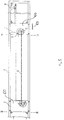
- Fig. 2 shows the buffer conveyor (16) in side view.
- the buffer conveyor (16) contains at least two parallel endless belts or at least two endless chains (28), which are shown in broken lines in FIG. 2.
- Pairs of deflecting rollers (30), (31), (32), (33) are rotatably mounted in an upper row on supports that are not identified in any more detail.
- the deflection rollers (30) to (33), which are arranged at the same height, have teeth, not shown, in which the chains (28) engage, which on each roller move from a vertical upward movement into a vertical one Downward movement can be redirected.
- deflection rollers (10), (12) In the vicinity of the lower end of the buffer conveyor (16) there are pairs of two deflection rollers (10), (12) each on an outside of the buffer conveyor (16).
- the respective chain (28) is guided from the externally arranged upper deflection roller (33) over the deflection roller (10) below this deflection roller (33), from which the chain (28) via the deflection roller (12) to the deflection roller (30 ) is performed.
- the deflection roller (12) is located below the deflection roller (30).
- the deflection rollers (10), (12) have smaller diameters than the deflection rollers (30) to (33).
- deflection rollers (34), (35), (36), which have the same diameter as the deflection rollers (30) to (33), are arranged in a higher position between the deflection rollers (10), (12).
- the lower peripheral points of the deflection rollers (34), (35), (36) are located above the tracks of the chains (28).
- the deflection rollers (34), (35), (36), like the deflection rollers (30) to (33), have teeth, not shown, in which the respective chain (28) engages.
- Each deflection roller (34), (35), (36) changes the transport direction of the respective chain (28) from the downward direction to the upward direction.
- the lateral boundaries (26) extend parallel to the chains (28) and end each a little above the deflection rollers (34), (35), (36). At the deflection rollers (30) at a distance which is somewhat greater than the length of the webs (21), (22), the boundary (26) begins at the vertical (42) extending through the axis of rotation of the deflection rollers (30). The boundary (26) ends laterally next to the deflection rollers (33).
- the webs (21) projecting from the chains (28) enclose receiving areas (23) between two adjacent webs (21).
- An input point (43) for the rod-shaped material (13) is located on the top of the deflection rollers (30), over which a feed slope (44) ends.
- the higher points (50) are located on the side next to the movement paths which are claimed by the chains (28) and the webs (21).
- the deepest points (51) and the stops (52) are also located to the side of the trajectories traversed by the chains (28) and the webs (21).
- the locations (50) lie in the area of the chain parts running downwards. In contrast, the locations (51) are in the area of the chain parts moved upwards.
- the rod-shaped materials (13) detected by the webs (21) at the entry point (43) are moved downwards until their sections projecting over the chains (28) and the webs (21) meet the material receiving bevel (47) on which they roll or slide in the direction of location (51). From the point (51) protruding sections are detected by the upwardly moving webs (21) of the chains (28). The materials are then moved upwards, deflected by the deflecting rollers (31) and moved downwards to the material receiving slope (48). They are grasped by the latter in the manner described above in connection with the material receiving slope (47) and made available at the point (51) for the upward transport. The same process is repeated on the material take-up slope (49).
- the parallel deflection rollers (30) to (33) and (34), (35), (36) are connected to one another in particular via rigid axles which are rotatably mounted. In this way, a synchronous movement of the parallel chains (28) is ensured.
- FIG 3 shows the buffer conveyor (16) in the area of the deflection rollers (31) in detail.
- the webs (21) are attached, against which the materials (13) lie.
- the webs (21) have trapezoidal sections (54) which adjoin the sections (53) to the outside and are guided in grooves in the boundaries (26).
- the trapezoidal, outwardly widening sections (54) ensure that the materials (13) lying on the webs (21) cannot reach the boundaries (26) and slide along them.
- the limits (26) are therefore also safety devices.
- the boundaries (26) ensure that the materials (13) -in Direction of transport seen - side by side or one above the other.
- the material receiving slope (48) is connected close to the point (50) with a carrier (55) which is attached to the frame of the buffer conveyor (16).
- the lower ends of the boundaries (26) are chamfered and attached to a profile carrier (56).
- the delivery bevel (46) leads the materials (13) to a bending device.
- the distance between the two parallel chains is matched to the minimum material length. If the length of the materials transported by the buffer conveyor can fluctuate over a very large range, it is advisable to provide several parallel chains at intervals with the corresponding deflection rollers, webs and limits.
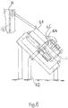
- FIG. 5 shows an inventive bending device which has the following essential elements:
- Two bending carriages (1) are supported on rollers (7) on a chassis (12) in order to be moved along them by means of motors (10) extending from the chassis (12).
- the connection between the motors (10) and the bending slide (1) can be made via chains, not specified.
- the rollers (7) are supported on rails or iron profiles (25), which originate from oblique U-beams (27) arranged in the end regions of the bending device. These are in turn attached to a floor surface (59) via profiles or supports (28) and (29).
- Each bending slide (1) has a table-shaped base plate (60), of which a bending tool in the form of two stationary bending rollers (2) with optionally one of the driving rollers (3), a swivel motor (5) for pivoting the driving roller (3 ) and a cylinder (6) to adjust the driving roller (3).
- a cover plate (61) which specifies the plane in or parallel to which the rod-shaped material (13) is bent.
- the plane (61) is penetrated by the bending rollers (2) and, during bending, by the driving roller (3), which can be withdrawn from the bending plane (61) by means of a cylinder (4).
- the driving roller (3) is pivoted via sprockets (8) and (9), the sprocket (9) starting from the pivot motor (5).
- insertion and extension arms (62) which can also be generally referred to as receiving devices, start from the base surface (59), below the travel path (indicated by arrow 63 in FIG. 2) of the bending slide (1).
- the insertion and extension arms (62) can be pivoted in such a way that they do not hinder the movement of the bending slide (1). This is possible because the space underneath the base plates (60) is largely free, in particular there is no obstruction by the drives (10) for moving the bending slides (1).
- the loading and unloading arms (62) have a pivotable end section (64) with a slot-shaped receptacle (65) into which the material (13) released by the buffer conveyor (16) and sliding along the plane (61) slides.
- the clear width of the slot (65) is chosen so that the rod-shaped material (13) is also arranged in one layer.
- the driving roller (3) As soon as the material is taken up by the section (64), it is placed between the bending rollers (2) of the bending tool, in order to then bend the material to the desired extent by pivoting the driving roller (3).
- the driving roller (3) and one of the bending rollers (2) can be pivoted. Aligning the driver roller (3) with the corresponding bending roller (2) and adjusting the bending radius is carried out by adjusting the driver roller (3) using the cylinder (6) or an equivalent actuator.
- the driving roller only has to be aligned with the desired bending roller (2).
- the driver roller (3) is withdrawn from the bending plane (32) by means of a cylinder (6), that is, sunk so that the material (13) cannot hinder the adjustment of the driver roller (3). Consequently, bending of the material to be bent (13) can be carried out in a clockwise or counterclockwise direction.
- the pivot point of the driving roller (3) can be adjusted by means of the cylinder (6) in such a way that the pivot point lies on the central axis of the bending roller (2), around which the driving roller (3) for bending the Materials (13) to be pivoted.
- insertion or extension arm (62) is shown in FIG. 6, in practice several insertion and extension arms (62), preferably arranged at the same distance from one another, are arranged along the travel paths of the bending slides (1). This ensures that the rod-shaped material (13) does not deflect when it is inserted, as a result of which the final shape of the bent material would otherwise deviate from the specified geometry.
- the bending slides (1) In order to prevent an uncontrolled evasion of the material (13) during bending, the bending slides (1) have clamping cylinders (11), which at the same time perform the function of a counter bearing.
- Fig. 8 bending positions are shown purely schematically.
- the first bending process can take place at any point on the material (13), the supply being the right end (68) of the material (13) - used in the exemplary embodiment - as the measuring point; because the material start as a position point is always in the same place.
- a change also does not take place if the material lengths are different, as is shown in FIG. 5.
Landscapes
- Engineering & Computer Science (AREA)
- Mechanical Engineering (AREA)
- Bending Of Plates, Rods, And Pipes (AREA)
Applications Claiming Priority (4)
| Application Number | Priority Date | Filing Date | Title |
|---|---|---|---|
| DE19904031463 DE4031463A1 (de) | 1990-10-05 | 1990-10-05 | Verfahren und anordnung zum foerdern und biegen von stabfoermigen materialien |
| DE4031463 | 1990-10-05 | ||
| DE9103674U DE9103674U1 (de) | 1991-03-26 | 1991-03-26 | Vorrichtung zum Fördern und Biegen von stabförmigen Materialien |
| DE9103674U | 1991-03-26 |
Publications (2)
| Publication Number | Publication Date |
|---|---|
| EP0479220A2 true EP0479220A2 (fr) | 1992-04-08 |
| EP0479220A3 EP0479220A3 (en) | 1992-06-03 |
Family
ID=25897453
Family Applications (1)
| Application Number | Title | Priority Date | Filing Date |
|---|---|---|---|
| EP19910116732 Withdrawn EP0479220A3 (en) | 1990-10-05 | 1991-10-01 | Method of and device for transporting and working rod-shaped materials |
Country Status (1)
| Country | Link |
|---|---|
| EP (1) | EP0479220A3 (fr) |
Cited By (3)
| Publication number | Priority date | Publication date | Assignee | Title |
|---|---|---|---|---|
| EP0579593A1 (fr) * | 1992-07-16 | 1994-01-19 | Peter Lisec | Dispositif pour la fabrication de cadres d'espacement pour vitres isolantes à partir de profilés d'écartement creux |
| AT401242B (de) * | 1992-07-16 | 1996-07-25 | Lisec Peter | Vorrichtung zum herstellen von abstandhalterrahmen für isolierglasscheiben aus hohlprofilleisten |
| AT401243B (de) * | 1992-07-16 | 1996-07-25 | Lisec Peter | Vorrichtung zum herstellen von abstandhalterrahmen für isolierglasscheiben aus hohlprofilleisten |
Family Cites Families (6)
| Publication number | Priority date | Publication date | Assignee | Title |
|---|---|---|---|---|
| DE7216864U (de) * | 1972-08-31 | Hasenclever Gmbh | Vorrichtung zur Zuführung von Stabmaterial zu Stauchmaschinen u. dgl | |
| DE1290081B (de) * | 1961-04-12 | 1969-02-27 | Schneider Armand | Anlage zum Zufoerdern und Ablegen von Langmaterial, insbesondere Betoniereisen |
| JPS55126326A (en) * | 1979-03-23 | 1980-09-30 | Kajima Corp | Method and apparatus for manufacturing steel bar for use of reinforced concrete |
| AT367322B (de) * | 1980-01-16 | 1982-06-25 | Evg Entwicklung Verwert Ges | Anlage zum herstellen von buegeln verschiedener gestalt und groesse, insbesondere von betonbewehrungsbssgeln |
| US4766754A (en) * | 1986-04-28 | 1988-08-30 | Watt Yang | Continuous process for bending long rods or tubes |
| US4763506A (en) * | 1987-03-13 | 1988-08-16 | Zeng Jun Lang | Automatic tube bending machine |
-
1991
- 1991-10-01 EP EP19910116732 patent/EP0479220A3/de not_active Withdrawn
Cited By (4)
| Publication number | Priority date | Publication date | Assignee | Title |
|---|---|---|---|---|
| EP0579593A1 (fr) * | 1992-07-16 | 1994-01-19 | Peter Lisec | Dispositif pour la fabrication de cadres d'espacement pour vitres isolantes à partir de profilés d'écartement creux |
| US5394725A (en) * | 1992-07-16 | 1995-03-07 | Lisec; Pater | Apparatus for the production of spacer frames for insulating glass panes from hollow profile strips |
| AT401242B (de) * | 1992-07-16 | 1996-07-25 | Lisec Peter | Vorrichtung zum herstellen von abstandhalterrahmen für isolierglasscheiben aus hohlprofilleisten |
| AT401243B (de) * | 1992-07-16 | 1996-07-25 | Lisec Peter | Vorrichtung zum herstellen von abstandhalterrahmen für isolierglasscheiben aus hohlprofilleisten |
Also Published As
| Publication number | Publication date |
|---|---|
| EP0479220A3 (en) | 1992-06-03 |
Similar Documents
| Publication | Publication Date | Title |
|---|---|---|
| DE4100769C2 (de) | Vorrichtung zum Fördern von Produkten in einer Verpackungsmaschine | |
| DE69422661T2 (de) | Verfahren und Vorrichtung zum Einwickeln von Gegenständen | |
| EP0623542A1 (fr) | Dispositif pour empiler un chant de feuilles imprimées | |
| DE3502611C2 (fr) | ||
| DE69718374T2 (de) | Verfahren und Vorrichtung zum geordneten Abführen von ungeordnet zugeführten Produkten | |
| EP0698569A1 (fr) | Installation pour retourner des objets sur une voie de transport, notamment pour retourner des couvercles, des boîtes et similaires | |
| DE19510649A1 (de) | Transportvorrichtung | |
| DE3038058A1 (de) | Einrichtung zum aufstapeln von flachen gegenstaenden,insbesondere von faltschachtel-zuschnitten | |
| DE68909967T2 (de) | Vorrichtung zum Biegen von Teigstücken. | |
| EP0579593B1 (fr) | Dispositif pour la fabrication de cadres d'espacement pour vitres isolantes à partir de profilés d'écartement creux | |
| EP0453806A1 (fr) | Installation pour empiler des pièces constituées d'éléments plats séparés ou de paquets desdits éléments plats | |
| EP1351783A1 (fr) | Dispositif de coupe transversale de bandes metalliques | |
| DE3047600A1 (de) | Vorrichtung zum aufnehmen, zur lageverschiebung und zum stapeln von stabfoermigen gegenstaenden wie stangen und leisten aus holz oder dergleichen (z.b. von profilstaeben fuer bilderrahmen) | |
| EP0371232B1 (fr) | Procédé de regroupement étagé de produits et dispositif de mise en oeuvre de ce procédé | |
| EP0182071B1 (fr) | Dispositif pour empiler des articles plats munis de deux trous de position, de préférence des sacs fabriqués à partir de feuilles en matière plastique | |
| DE102005002532A1 (de) | Vorrichtung und Verfahren zum automatisierten und zeitgleichen Bereitstellen und Wechseln von mindestens zwei Rollen aus Papierbahnen oder dergleichen für einen nachgeordneten Formatschneider | |
| DE4204967A1 (de) | Vorrichtung zum transport mindestens einer kanne zwischen einer faserbandabliefernden spinnereimaschine und einer faserbandgespeisten spinnereimaschine | |
| EP1072546A1 (fr) | Convoyeur pour assembler et traiter des produits imprimés | |
| AT393641B (de) | Vorrichtung zum biegen von stahlstaeben zu betonbewehrungselementen | |
| DE60309133T2 (de) | Vorrichtung zur anpassung des abstandes zwischen förderfingern an die länge des produktes | |
| EP0419447B1 (fr) | Méthode et dispositif pour décalaminage de barres d'acier rondes | |
| DE2328696A1 (de) | Vorrichtung zum stapeln von stabfoermigem gut, insbesondere walzprofilen | |
| DE3828879C2 (fr) | ||
| DE4031463A1 (de) | Verfahren und anordnung zum foerdern und biegen von stabfoermigen materialien | |
| EP1771360B1 (fr) | Dispositif de transport |
Legal Events
| Date | Code | Title | Description |
|---|---|---|---|
| PUAI | Public reference made under article 153(3) epc to a published international application that has entered the european phase |
Free format text: ORIGINAL CODE: 0009012 |
|
| AK | Designated contracting states |
Kind code of ref document: A2 Designated state(s): AT BE CH DE DK ES FR GB GR IT LI LU NL SE |
|
| PUAL | Search report despatched |
Free format text: ORIGINAL CODE: 0009013 |
|
| AK | Designated contracting states |
Kind code of ref document: A3 Designated state(s): AT BE CH DE DK ES FR GB GR IT LI LU NL SE |
|
| 17P | Request for examination filed |
Effective date: 19920812 |
|
| 17Q | First examination report despatched |
Effective date: 19931029 |
|
| STAA | Information on the status of an ep patent application or granted ep patent |
Free format text: STATUS: THE APPLICATION IS DEEMED TO BE WITHDRAWN |
|
| 18D | Application deemed to be withdrawn |
Effective date: 19940309 |