EP0479973B1 - Hohlräumiger schleifkörper mit mehrlagiger schleifschicht - Google Patents
Hohlräumiger schleifkörper mit mehrlagiger schleifschicht Download PDFInfo
- Publication number
- EP0479973B1 EP0479973B1 EP91907212A EP91907212A EP0479973B1 EP 0479973 B1 EP0479973 B1 EP 0479973B1 EP 91907212 A EP91907212 A EP 91907212A EP 91907212 A EP91907212 A EP 91907212A EP 0479973 B1 EP0479973 B1 EP 0479973B1
- Authority
- EP
- European Patent Office
- Prior art keywords
- grit
- cavities
- metal
- base member
- abrasive tool
- Prior art date
- Legal status (The legal status is an assumption and is not a legal conclusion. Google has not performed a legal analysis and makes no representation as to the accuracy of the status listed.)
- Expired - Lifetime
Links
- 229910052751 metal Inorganic materials 0.000 claims abstract description 45
- 239000002184 metal Substances 0.000 claims abstract description 45
- 239000002245 particle Substances 0.000 claims description 17
- 238000009826 distribution Methods 0.000 claims description 3
- 229910045601 alloy Inorganic materials 0.000 claims description 2
- 239000000956 alloy Substances 0.000 claims description 2
- CWYNVVGOOAEACU-UHFFFAOYSA-N Fe2+ Chemical compound [Fe+2] CWYNVVGOOAEACU-UHFFFAOYSA-N 0.000 claims 2
- UONOETXJSWQNOL-UHFFFAOYSA-N tungsten carbide Chemical compound [W+]#[C-] UONOETXJSWQNOL-UHFFFAOYSA-N 0.000 claims 1
- 238000009827 uniform distribution Methods 0.000 abstract description 2
- 238000005520 cutting process Methods 0.000 description 13
- 239000000463 material Substances 0.000 description 10
- 230000000694 effects Effects 0.000 description 3
- XEEYBQQBJWHFJM-UHFFFAOYSA-N Iron Chemical compound [Fe] XEEYBQQBJWHFJM-UHFFFAOYSA-N 0.000 description 2
- 239000003082 abrasive agent Substances 0.000 description 2
- 230000015572 biosynthetic process Effects 0.000 description 2
- 238000004519 manufacturing process Methods 0.000 description 2
- 229910052721 tungsten Inorganic materials 0.000 description 2
- 239000010937 tungsten Substances 0.000 description 2
- -1 tungsten carbides Chemical class 0.000 description 2
- 229910001209 Low-carbon steel Inorganic materials 0.000 description 1
- 238000005219 brazing Methods 0.000 description 1
- 239000012141 concentrate Substances 0.000 description 1
- 239000000470 constituent Substances 0.000 description 1
- 230000007423 decrease Effects 0.000 description 1
- 230000003247 decreasing effect Effects 0.000 description 1
- 230000004907 flux Effects 0.000 description 1
- 230000017525 heat dissipation Effects 0.000 description 1
- 229910052742 iron Inorganic materials 0.000 description 1
- 238000002844 melting Methods 0.000 description 1
- 230000008018 melting Effects 0.000 description 1
- 238000000034 method Methods 0.000 description 1
- 239000003870 refractory metal Substances 0.000 description 1
- 239000000126 substance Substances 0.000 description 1
- 239000011800 void material Substances 0.000 description 1
Images
Classifications
-
- B—PERFORMING OPERATIONS; TRANSPORTING
- B24—GRINDING; POLISHING
- B24D—TOOLS FOR GRINDING, BUFFING OR SHARPENING
- B24D3/00—Physical features of abrasive bodies, or sheets, e.g. abrasive surfaces of special nature; Abrasive bodies or sheets characterised by their constituents
- B24D3/02—Physical features of abrasive bodies, or sheets, e.g. abrasive surfaces of special nature; Abrasive bodies or sheets characterised by their constituents the constituent being used as bonding agent
- B24D3/04—Physical features of abrasive bodies, or sheets, e.g. abrasive surfaces of special nature; Abrasive bodies or sheets characterised by their constituents the constituent being used as bonding agent and being essentially inorganic
- B24D3/06—Physical features of abrasive bodies, or sheets, e.g. abrasive surfaces of special nature; Abrasive bodies or sheets characterised by their constituents the constituent being used as bonding agent and being essentially inorganic metallic or mixture of metals with ceramic materials, e.g. hard metals, "cermets", cements
-
- B—PERFORMING OPERATIONS; TRANSPORTING
- B24—GRINDING; POLISHING
- B24D—TOOLS FOR GRINDING, BUFFING OR SHARPENING
- B24D18/00—Manufacture of grinding tools or other grinding devices, e.g. wheels, not otherwise provided for
Definitions
- This invention relates generally to an abrasive wheel for use in abrading various types of materials. More particularly, the invention utilizes crushed, sintered refractory metal grits such as sintered tungsten carbides and like hard particle substances which can be braze metal joined (or joined by other means) to a supporting base member.
- crushed, sintered refractory metal grits such as sintered tungsten carbides and like hard particle substances which can be braze metal joined (or joined by other means) to a supporting base member.
- the present invention is directed to an abrasive wheel for use in the abrading of various materials. This tool maintains all the advantages of the prior art devices, while providing enhanced performance and a longer useful life.
- One object, therefore, of the present invention is to provide a generally uniform and layered distribution of small metal grit over the smooth lands area of the abrasive wheel which will allow the cutting surface of the abrasive wheel to achieve a longer useful life.
- a second object of the present invention is to allow for a more aggressive cutting action of the wheel by providing for improved removal of abraded material from the cutting surface of the wheel.
- a third object of the present invention is to impart an enhanced cutting ability to a wheel while employing a smaller abrasive particle size, resulting in a finer texture left on the work piece.
- a fourth object of the present invention is to provide a cutting tool which runs cooler and more efficiently than prior art devices through improved heat distribution from contact to non-contact surfaces, as well as a lowered torque due to a shortened extension of the grit particles from the metal surface.
- a fifth object of the present invention is to provide a cutting tool which is more economical to manufacture.
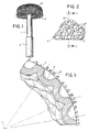
- FIG 2 the generally uniform distribution of metal grit 4 over the smooth portion of "lands" area 5 of supporting base member 3 is illustrated. Note that no grit occupies the cavities 6 on base member 3.
- Figure 3 illustrates the disposition of the magnetized, metal grit 4. The grit is not confined to extending radially outward from a center point, but rather forms interconnected layers of vertically and horizontally positioned grit. When a small grit particle breaks away, this layered effect enables another grit particle to be exposed.
- the present invention teaches the use of cavities or recesses distributed either uniformly or non-uniformly along the supporting base member 3; the periphery of these cavities faces the metal base member 1.
- These cavities may be of any convenient shape, e.g., round, square, etc.
- the spacing of the cavities can be varied to conform with the desired action of the wheel and the size of the abrasive material to be applied.
- the cavities may be spaced in straight rows or staggered in any number of design combinations. It can be appreciated by those skilled in the art that the size and spacing of the cavities can be changed to achieve an abrasive wheel with a wide operating range.
- the cavities provide an important structural advantage which further enhances the cutting ability of the wheel.
- the material removed by the wheel has the free area in the cavities to retreat to. At the point of contact with the wheel, portions of the abraded material are displaced within the individual cavities. As the high speed abrasive wheel rotates, the abraded material is expelled from the cavities by centrifugal force. In contrast, removed material in prior art devices tended to become trapped and load up on the abrasive protrusions, reducing the wheel's cutting ability. Further, some conventional wheels had holes on their outer working surface.
- Such configurations not only physically reduce the strength of the wheel, but also allow the abraded material to pass through the holes and build up on the inner surface of the wheel, causing the holes to close. Further, it has been found that a magnetic field applied to a wheel with holes causes the grit to lie flat and ineffectual upon the metal surface.
- the cavities of the present invention allow for a more aggressive cutting action of the wheel by ameliorating the effect of abraded material buildup.
- metal grit is generally uniformly distributed over the lands area of the supporting base member, but not on the inner surface of the cavities.
- the prior art taught the formation of bunched grit on the outermost periphery of the protuberances, and not on the lands area between the protuberances. This is due to the fact that the metal grit, as a result of magnetic flux lines which naturally concentrate in areas of discontinuity, is forced to points on the external metal surface that exhibit rapid contour changes.
- smaller metal grit can be utilized than that of the prior art, as the grit of the present invention need not be selected such that its length exceeds its smallest cross section.
- These smaller size particles impart an enhanced cutting ability to the wheel, as the resulting decreased cutting clearance makes the wheel easier to control, and leaves a finer texture on the work piece.
- the longer particles of the prior art are more subject to fracturing and breakage.
- the layered, interconnected grit of the present invention imparts a longer useful life to the abrasive wheel for three reasons.
- First, the layered configuration insures that when one piece of grit breaks away, another grit particle below it will be exposed for cutting.
- Second, the dimpled effect on the supporting base member allows the tool to run cooler and more efficiently. This is due to the fact that the inner surface of a wheel with recesses encompasses a greater surface area than a smooth surface. This increased surface area provides enhanced heat transfer capabilities to the metal surface, and thus improves heat dissipation as the wheel is used.
- Third, the smaller grit extends a shorter distance from the supporting base member than prior art tools. This shortened distance lowers the torque and thus the force applied to individual grit particles, which decreases the energy required to do work. More total work is accomplished, however, due to the increased number of smaller grit particles.
- the heat transfer capabilities of the present invention are novel for another reason as well.
- the distal portions of the grit particles overhang individual cavities.
- This novel structuring allows the individual cavities to act as natural heat sinks: the heat from the grit particles is transferred from the distal ends of the grit to the cavities, and the rotation of the wheel then cools both the inner and outer surfaces of the recesses.
- the present invention also allows for more economical manufacture of these abrading tools. This economy is achieved through the previously described more efficient utilization of smaller abrasive particles than conventional wheels.
- the metal grit consists of sintered tungsten carbides which can be braze metal joined (or joined by other means) to the supporting base member.
- the supporting base member is usually constructed out of a mild steel or other iron base alloy which has a high enough melting temperature beyond that of the brazing metal used to bond the various constituents of the finally processed device. (See U.S. Patent No. 3,918,217).
Landscapes
- Engineering & Computer Science (AREA)
- Chemical & Material Sciences (AREA)
- Mechanical Engineering (AREA)
- Ceramic Engineering (AREA)
- Inorganic Chemistry (AREA)
- Manufacturing & Machinery (AREA)
- Polishing Bodies And Polishing Tools (AREA)
- Physical Or Chemical Processes And Apparatus (AREA)
- Compounds Of Alkaline-Earth Elements, Aluminum Or Rare-Earth Metals (AREA)
- Ceramic Products (AREA)
Claims (9)
- Schleifwerkzeug mit: einem Eisen- oder Eisenlegierungsgrundkörper (1), der mehrere durch eine allgemein durchgehende und im wesentlichen glatte äußere Stegfläche (5) getrennte Hohlräume (6) enthält; und Teilchen von Metallkörnern (4), die über die Fläche des Grundkörpers (1) verteilt und über ein Hartlot mit dem Gruudkörper (1) verbunden sind, dadurch gekennzeichnet, daß die Körner (4) allgemein gleichmäßig auf der Stegfläche (5) und nicht in den Hohlräumen (6) angeordnet sind, wobei die bestimmte Verteilung durch Anlegen eines Magnetfeldes erreicht werden kann.
- Schleifwerkzeug nach Anspruch 1, dadurch gekennzeichnet, daß die Metallkörner (1) aus Wolframkarbid bestehen.
- Schleifwerkzeug nach Anspruch 1 oder 2, dadurch gekennzeichnet, daß durch den Betrieb des Werkzeuge erzeugte Wärme durch Übertragung von den Metallkörnern auf die Hohlräume abgeleitet wird.
- Schleifwerkzeug nach einem der vorhergehenden Ansprüche, dadurch gekennzeichnet, daß die Hohlräume (6) in gleichmäßigem Anstand über den Grundkörper (1) verteilt sind.
- Schleifwerkzeug nach Anspruch 4, dadurch gekennzeichnet, daß die Hohlräume (6) nicht gleichmäßiger Größe und Form sind.
- Schleifwerkzeug nach Anspruch 4, dadurch gekennzeichnet, daß die Hohlräume (6) gleichmäßiger Größe und Form sind.
- Schleifwerkzeug nach Anspruch 4 oder 5, dadurch gekennzeichnet, daß die Hohlräume (6) allgemein konkav sind.
- Schleifwerkzeug nach einem der vorhergehenden Ansprüche, dadurch gekennzeichnet, daß die distalen Teile der Metallkörner (4) über den Hohlräumen (6) hängen.
- Schleifwerkzeug nach einem der vorhergehenden Ansprüche, dadurch gekennzeichnet, daß die Metallkornteilchen (4) über ein Hartlot miteinander und mit dem Grundkörper (1) in miteinander verbundenen Schichten verbunden sind, wodurch beim Abbrechen oder im Gebrauch verschlissenen einzelnen Kornteilchen (4) andere Teilchen zur Verwendung zur Verfügung gestellt werden.
Applications Claiming Priority (3)
| Application Number | Priority Date | Filing Date | Title |
|---|---|---|---|
| US51139390A | 1990-04-18 | 1990-04-18 | |
| US511393 | 1990-04-18 | ||
| PCT/US1991/001772 WO1991016175A1 (en) | 1990-04-18 | 1991-03-15 | Cavitied abrading device with layered grit |
Publications (3)
| Publication Number | Publication Date |
|---|---|
| EP0479973A1 EP0479973A1 (de) | 1992-04-15 |
| EP0479973A4 EP0479973A4 (en) | 1992-07-08 |
| EP0479973B1 true EP0479973B1 (de) | 1995-12-06 |
Family
ID=24034712
Family Applications (1)
| Application Number | Title | Priority Date | Filing Date |
|---|---|---|---|
| EP91907212A Expired - Lifetime EP0479973B1 (de) | 1990-04-18 | 1991-03-15 | Hohlräumiger schleifkörper mit mehrlagiger schleifschicht |
Country Status (11)
| Country | Link |
|---|---|
| EP (1) | EP0479973B1 (de) |
| JP (1) | JP3184519B2 (de) |
| AT (1) | ATE131096T1 (de) |
| AU (1) | AU647470B2 (de) |
| BR (1) | BR9105723A (de) |
| CA (1) | CA2058960C (de) |
| DE (1) | DE69115214T2 (de) |
| DK (1) | DK0479973T3 (de) |
| ES (1) | ES2079651T3 (de) |
| WO (1) | WO1991016175A1 (de) |
| ZA (1) | ZA912669B (de) |
Families Citing this family (2)
| Publication number | Priority date | Publication date | Assignee | Title |
|---|---|---|---|---|
| US5239784A (en) * | 1990-04-18 | 1993-08-31 | B & J Manufacturing Company | Cavitied abrading device with smooth lands area and layered grit |
| JP3260764B2 (ja) * | 1995-06-07 | 2002-02-25 | サン‐ゴバン アブレイシブズ,インコーポレイティド | 模様状の切削表面を有する切削工具 |
Family Cites Families (4)
| Publication number | Priority date | Publication date | Assignee | Title |
|---|---|---|---|---|
| US3918217A (en) * | 1972-07-24 | 1975-11-11 | Lloyd R Oliver & Company | Abrading device with protrusions on metal bonded abrasive grits |
| DE2758285A1 (de) * | 1977-12-27 | 1979-06-28 | Honda Motor Co Ltd | Schleifscheibe und verfahren zu ihrer herstellung |
| US4821461A (en) * | 1987-11-23 | 1989-04-18 | Magnetic Peripherals Inc. | Textured lapping plate and process for its manufacture |
| US4908046A (en) * | 1989-02-14 | 1990-03-13 | Wiand Ronald C | Multilayer abrading tool and process |
-
1991
- 1991-03-15 WO PCT/US1991/001772 patent/WO1991016175A1/en not_active Ceased
- 1991-03-15 DE DE69115214T patent/DE69115214T2/de not_active Expired - Lifetime
- 1991-03-15 CA CA002058960A patent/CA2058960C/en not_active Expired - Fee Related
- 1991-03-15 EP EP91907212A patent/EP0479973B1/de not_active Expired - Lifetime
- 1991-03-15 ES ES91907212T patent/ES2079651T3/es not_active Expired - Lifetime
- 1991-03-15 JP JP50641791A patent/JP3184519B2/ja not_active Expired - Lifetime
- 1991-03-15 AT AT91907212T patent/ATE131096T1/de not_active IP Right Cessation
- 1991-03-15 DK DK91907212.4T patent/DK0479973T3/da active
- 1991-03-15 BR BR919105723A patent/BR9105723A/pt not_active IP Right Cessation
- 1991-03-15 AU AU75489/91A patent/AU647470B2/en not_active Expired
- 1991-04-10 ZA ZA912669A patent/ZA912669B/xx unknown
Also Published As
| Publication number | Publication date |
|---|---|
| CA2058960C (en) | 1999-11-09 |
| ZA912669B (en) | 1992-01-29 |
| JP3184519B2 (ja) | 2001-07-09 |
| JPH05500778A (ja) | 1993-02-18 |
| CA2058960A1 (en) | 1991-10-19 |
| EP0479973A4 (en) | 1992-07-08 |
| ATE131096T1 (de) | 1995-12-15 |
| AU7548991A (en) | 1991-11-11 |
| DE69115214T2 (de) | 1996-06-20 |
| WO1991016175A1 (en) | 1991-10-31 |
| ES2079651T3 (es) | 1996-01-16 |
| EP0479973A1 (de) | 1992-04-15 |
| DE69115214D1 (de) | 1996-01-18 |
| BR9105723A (pt) | 1992-08-04 |
| DK0479973T3 (da) | 1996-03-04 |
| AU647470B2 (en) | 1994-03-24 |
Similar Documents
| Publication | Publication Date | Title |
|---|---|---|
| US3918217A (en) | Abrading device with protrusions on metal bonded abrasive grits | |
| US5669943A (en) | Cutting tools having textured cutting surface | |
| JP4271865B2 (ja) | 焼結物品を製造する方法及びそれによって生産される製品 | |
| JP4282607B2 (ja) | 歯車型加工チップ及びこれを取付けた加工工具 | |
| KR100764912B1 (ko) | 절삭공구용 절삭팁 및 절삭공구 | |
| US3596649A (en) | Abrasive tool and process of manufacture | |
| KR100433194B1 (ko) | 편마모방지용 세그먼트를 갖는 연마휠 | |
| JPH07164325A (ja) | 研削工具のための研削ライニング及び研削ライニングの製造方法 | |
| US5239784A (en) | Cavitied abrading device with smooth lands area and layered grit | |
| US5871005A (en) | Wheel cutter blade | |
| WO2002066217A1 (en) | Machining tips and cutting wheel, grinding wheel and drilling wheel therewith | |
| CA2058960C (en) | Cavitied abrading device with layered grit | |
| US20100326416A1 (en) | High speed abrasive cutting blade with simulated teeth | |
| KR102691720B1 (ko) | 복합 드레서 | |
| JPH0376608A (ja) | 円筒型ホールソー | |
| JP2001038630A (ja) | 超砥粒工具及びその製造方法 | |
| JPH0677901B2 (ja) | 鋳物用ダイヤモンドカッター | |
| JP3361631B2 (ja) | ブレード | |
| JP3097356B2 (ja) | 穿孔用ビットの製造方法 | |
| JPS61152375A (ja) | 回転切断刃 | |
| JPH10202533A (ja) | ダイヤモンド切断砥石 | |
| JP3411233B2 (ja) | 研削工具の製造方法 | |
| CN213917799U (zh) | 一种斜齿钎焊弹簧钢磨轮 | |
| JPH1076470A (ja) | 研磨用砥石車 | |
| JP3922900B2 (ja) | 軸付き砥石 |
Legal Events
| Date | Code | Title | Description |
|---|---|---|---|
| PUAI | Public reference made under article 153(3) epc to a published international application that has entered the european phase |
Free format text: ORIGINAL CODE: 0009012 |
|
| 17P | Request for examination filed |
Effective date: 19911207 |
|
| AK | Designated contracting states |
Kind code of ref document: A1 Designated state(s): AT BE CH DE DK ES FR GB GR IT LI LU NL SE |
|
| A4 | Supplementary search report drawn up and despatched |
Effective date: 19920515 |
|
| AK | Designated contracting states |
Kind code of ref document: A4 Designated state(s): AT BE CH DE DK ES FR GB GR IT LI LU NL SE |
|
| 17Q | First examination report despatched |
Effective date: 19930908 |
|
| GRAA | (expected) grant |
Free format text: ORIGINAL CODE: 0009210 |
|
| ITF | It: translation for a ep patent filed | ||
| AK | Designated contracting states |
Kind code of ref document: B1 Designated state(s): AT BE CH DE DK ES FR GB GR IT LI LU NL SE |
|
| PG25 | Lapsed in a contracting state [announced via postgrant information from national office to epo] |
Ref country code: GR Free format text: LAPSE BECAUSE OF FAILURE TO SUBMIT A TRANSLATION OF THE DESCRIPTION OR TO PAY THE FEE WITHIN THE PRESCRIBED TIME-LIMIT Effective date: 19951206 |
|
| REF | Corresponds to: |
Ref document number: 131096 Country of ref document: AT Date of ref document: 19951215 Kind code of ref document: T |
|
| REG | Reference to a national code |
Ref country code: ES Ref legal event code: FG2A Ref document number: 2079651 Country of ref document: ES Kind code of ref document: T3 |
|
| REF | Corresponds to: |
Ref document number: 69115214 Country of ref document: DE Date of ref document: 19960118 |
|
| REG | Reference to a national code |
Ref country code: CH Ref legal event code: NV Representative=s name: A. BRAUN, BRAUN, HERITIER, ESCHMANN AG PATENTANWAE |
|
| REG | Reference to a national code |
Ref country code: DK Ref legal event code: T3 |
|
| ET | Fr: translation filed | ||
| PLBE | No opposition filed within time limit |
Free format text: ORIGINAL CODE: 0009261 |
|
| STAA | Information on the status of an ep patent application or granted ep patent |
Free format text: STATUS: NO OPPOSITION FILED WITHIN TIME LIMIT |
|
| 26N | No opposition filed | ||
| REG | Reference to a national code |
Ref country code: GB Ref legal event code: IF02 |
|
| REG | Reference to a national code |
Ref country code: CH Ref legal event code: PUE Owner name: B & J ROCKET SALES AG Free format text: B & J MANUFACTURING COMPANY#700 WEST 193RD STREET#GLENWOOD ILLINOIS 60425 (US) -TRANSFER TO- B & J ROCKET SALES AG#REUSSENSTRASSE 5B#6340 BAAR (CH) Ref country code: CH Ref legal event code: NV Representative=s name: ROTTMANN, ZIMMERMANN + PARTNER AG |
|
| REG | Reference to a national code |
Ref country code: GB Ref legal event code: 732E |
|
| REG | Reference to a national code |
Ref country code: FR Ref legal event code: TP |
|
| PG25 | Lapsed in a contracting state [announced via postgrant information from national office to epo] |
Ref country code: DE Free format text: LAPSE BECAUSE OF NON-PAYMENT OF DUE FEES Effective date: 20071002 |
|
| PGRI | Patent reinstated in contracting state [announced from national office to epo] |
Ref country code: DE Effective date: 20080225 |
|
| PGFP | Annual fee paid to national office [announced via postgrant information from national office to epo] |
Ref country code: ES Payment date: 20100326 Year of fee payment: 20 Ref country code: LU Payment date: 20100331 Year of fee payment: 20 Ref country code: CH Payment date: 20100325 Year of fee payment: 20 Ref country code: DK Payment date: 20100325 Year of fee payment: 20 |
|
| PGFP | Annual fee paid to national office [announced via postgrant information from national office to epo] |
Ref country code: FR Payment date: 20100406 Year of fee payment: 20 |
|
| PGFP | Annual fee paid to national office [announced via postgrant information from national office to epo] |
Ref country code: GB Payment date: 20100326 Year of fee payment: 20 Ref country code: AT Payment date: 20100219 Year of fee payment: 20 |
|
| PGFP | Annual fee paid to national office [announced via postgrant information from national office to epo] |
Ref country code: IT Payment date: 20100329 Year of fee payment: 20 Ref country code: DE Payment date: 20100329 Year of fee payment: 20 Ref country code: BE Payment date: 20100324 Year of fee payment: 20 Ref country code: NL Payment date: 20100324 Year of fee payment: 20 |
|
| PGFP | Annual fee paid to national office [announced via postgrant information from national office to epo] |
Ref country code: SE Payment date: 20100329 Year of fee payment: 20 |
|
| REG | Reference to a national code |
Ref country code: DE Ref legal event code: R071 Ref document number: 69115214 Country of ref document: DE |
|
| REG | Reference to a national code |
Ref country code: NL Ref legal event code: V4 Effective date: 20110315 |
|
| BE20 | Be: patent expired |
Owner name: *B & J ROCKET SALES A.G. Effective date: 20110315 |
|
| REG | Reference to a national code |
Ref country code: CH Ref legal event code: PL |
|
| REG | Reference to a national code |
Ref country code: GB Ref legal event code: PE20 Expiry date: 20110314 |
|
| REG | Reference to a national code |
Ref country code: DK Ref legal event code: EUP |
|
| REG | Reference to a national code |
Ref country code: SE Ref legal event code: EUG |
|
| PG25 | Lapsed in a contracting state [announced via postgrant information from national office to epo] |
Ref country code: NL Free format text: LAPSE BECAUSE OF EXPIRATION OF PROTECTION Effective date: 20110315 |
|
| PG25 | Lapsed in a contracting state [announced via postgrant information from national office to epo] |
Ref country code: GB Free format text: LAPSE BECAUSE OF EXPIRATION OF PROTECTION Effective date: 20110314 |
|
| REG | Reference to a national code |
Ref country code: ES Ref legal event code: FD2A Effective date: 20120424 |
|
| PG25 | Lapsed in a contracting state [announced via postgrant information from national office to epo] |
Ref country code: ES Free format text: LAPSE BECAUSE OF EXPIRATION OF PROTECTION Effective date: 20110316 |
|
| PG25 | Lapsed in a contracting state [announced via postgrant information from national office to epo] |
Ref country code: DE Free format text: LAPSE BECAUSE OF EXPIRATION OF PROTECTION Effective date: 20110315 |