EP0480037B1 - Dispositif d'actionnement des machines de deplacement et de travail d'un excavateur hydraulique - Google Patents
Dispositif d'actionnement des machines de deplacement et de travail d'un excavateur hydraulique Download PDFInfo
- Publication number
- EP0480037B1 EP0480037B1 EP90909838A EP90909838A EP0480037B1 EP 0480037 B1 EP0480037 B1 EP 0480037B1 EP 90909838 A EP90909838 A EP 90909838A EP 90909838 A EP90909838 A EP 90909838A EP 0480037 B1 EP0480037 B1 EP 0480037B1
- Authority
- EP
- European Patent Office
- Prior art keywords
- separation mode
- mode
- working
- hydraulic
- separation
- Prior art date
- Legal status (The legal status is an assumption and is not a legal conclusion. Google has not performed a legal analysis and makes no representation as to the accuracy of the status listed.)
- Expired - Lifetime
Links
- 238000000926 separation method Methods 0.000 claims abstract description 61
- 239000003921 oil Substances 0.000 description 13
- 239000010720 hydraulic oil Substances 0.000 description 8
- 238000010586 diagram Methods 0.000 description 3
- 238000013016 damping Methods 0.000 description 1
- 230000000881 depressing effect Effects 0.000 description 1
- 230000000994 depressogenic effect Effects 0.000 description 1
- 239000012530 fluid Substances 0.000 description 1
- 230000004048 modification Effects 0.000 description 1
- 238000012986 modification Methods 0.000 description 1
Images


Classifications
-
- E—FIXED CONSTRUCTIONS
- E02—HYDRAULIC ENGINEERING; FOUNDATIONS; SOIL SHIFTING
- E02F—DREDGING; SOIL-SHIFTING
- E02F3/00—Dredgers; Soil-shifting machines
- E02F3/04—Dredgers; Soil-shifting machines mechanically-driven
- E02F3/28—Dredgers; Soil-shifting machines mechanically-driven with digging tools mounted on a dipper- or bucket-arm, i.e. there is either one arm or a pair of arms, e.g. dippers, buckets
- E02F3/36—Component parts
- E02F3/42—Drives for dippers, buckets, dipper-arms or bucket-arms
- E02F3/43—Control of dipper or bucket position; Control of sequence of drive operations
-
- E—FIXED CONSTRUCTIONS
- E02—HYDRAULIC ENGINEERING; FOUNDATIONS; SOIL SHIFTING
- E02F—DREDGING; SOIL-SHIFTING
- E02F9/00—Component parts of dredgers or soil-shifting machines, not restricted to one of the kinds covered by groups E02F3/00 - E02F7/00
- E02F9/20—Drives; Control devices
- E02F9/22—Hydraulic or pneumatic drives
- E02F9/2278—Hydraulic circuits
- E02F9/2296—Systems with a variable displacement pump
-
- E—FIXED CONSTRUCTIONS
- E02—HYDRAULIC ENGINEERING; FOUNDATIONS; SOIL SHIFTING
- E02F—DREDGING; SOIL-SHIFTING
- E02F9/00—Component parts of dredgers or soil-shifting machines, not restricted to one of the kinds covered by groups E02F3/00 - E02F7/00
- E02F9/20—Drives; Control devices
- E02F9/22—Hydraulic or pneumatic drives
- E02F9/2203—Arrangements for controlling the attitude of actuators, e.g. speed, floating function
-
- E—FIXED CONSTRUCTIONS
- E02—HYDRAULIC ENGINEERING; FOUNDATIONS; SOIL SHIFTING
- E02F—DREDGING; SOIL-SHIFTING
- E02F9/00—Component parts of dredgers or soil-shifting machines, not restricted to one of the kinds covered by groups E02F3/00 - E02F7/00
- E02F9/20—Drives; Control devices
- E02F9/22—Hydraulic or pneumatic drives
- E02F9/2221—Control of flow rate; Load sensing arrangements
- E02F9/2239—Control of flow rate; Load sensing arrangements using two or more pumps with cross-assistance
- E02F9/2242—Control of flow rate; Load sensing arrangements using two or more pumps with cross-assistance including an electronic controller
-
- E—FIXED CONSTRUCTIONS
- E02—HYDRAULIC ENGINEERING; FOUNDATIONS; SOIL SHIFTING
- E02F—DREDGING; SOIL-SHIFTING
- E02F9/00—Component parts of dredgers or soil-shifting machines, not restricted to one of the kinds covered by groups E02F3/00 - E02F7/00
- E02F9/20—Drives; Control devices
- E02F9/22—Hydraulic or pneumatic drives
- E02F9/2278—Hydraulic circuits
- E02F9/2292—Systems with two or more pumps
Definitions
- This invention relates to a device for operating traveling and working machines of a hydraulic excavator, and more particularly it pertains to such an operating device arranged such that a plurality of electrical control actuating valves are switchingly controlled by means of an input signal provided by a controller so that hydraulic oil discharged from a plurality of hydraulic pumps are caused to selectively flow into a respective actuator of the hydraulic excavator, thereby improving the operating and working performance of the traveling and working machines of the hydraulic excavator.
- Fig. 3 illustrates an example of such an electric-hydraulic control circuit for supplying operating hydraulic oil to leftward/rightward drive hydraulic motors and actuators of the working and swivelling machines by using a two-hydraulic pump system which has widely been used with the above-mentioned conventional hydraulic excavator.
- respective actuators such as a bucket cylinder 6, a leftward-drive motor 7, a boom cylinder 8, a swivel motor 9, and an arm cylinder 10 are connected, via electrical control actuating valves (not shown), to a hydraulic circuit 3 coupled to a hydraulic pump 2 which is driven by an engine 1.
- the respective actuators such as the bucket cylinder 6, leftward-drive motor 7, boom cylinder 8, arm cylinder 10,and a rightward-drive motor 11 are also connected, via the electrical control valves (not shown), to a hydraulic circuit 5 coupled to a hydraulic pump 4 which is driven by the engine 1.
- an electric signal converted from changes in the quantity of actuation of a traveling/actuating lever 13, a bucket/boom actuating lever 14, and an arm/swivel actuating lever 15 each of which comprises an electric lever is first transmitted to a controller 16 and then transmitted to the electrical control actuating valves as an output signal from the controller 16.
- a reference numeral 17 indicates a separation mode switch for switching the working mode of each actuator between a standard mode and a separation mode.
- this separation mode switch 17 By setting this separation mode switch 17 at the standard mode, the discharge hydraulic oil from the two hydraulic pumps 2 and 4 are caused to flow into each actuator either individually or in combination depending on the quantity of actuation of the above-mentioned actuating levers.
- the boom cylinder 8 and arm cylinder 10 are provided with the discharge oil from the two pumps. In this way, the working speed of the actuators is increased.
- the separation mode switch 17 by operating and setting the separation mode switch 17 at a traveling/working machine separation mode included in the separation mode, when only the traveling machine is operated, an independent circuit is formed with respect to the leftward-drive and rightward-drive motors so that the leftward-drive motor 7 is driven by means of the discharged oil pressure of the hydraulic pump 2 while the rightward-drive motor 11 is driven by means of the discharged oil pressure of the hydraulic pump 4.
- the leftward-drive and rightward-drive motors 7 and 11 are driven by means of the discharged oil pressure of the hydraulic pump 4, and the actuator (either one of 6, 8, 9, 10) of the working machine is driven by means of the discharged oil pressure of the hydraulic pump 2. In this way, in the separation mode, it is possible to prevent speed interference with respect to the actuators of the working machine by separating the hydraulic circuits 3 and 5.
- the working speed of the actuator becomes lower than when the operating device is set at the standard mode; thus, advantageously, the operability of the working machine is improved, and speed interference with respect to the actuators of the working machine can be prevented.
- the quantity of discharge hydraulic oil used to operate each actuator is the one provided by only one of the hydraulic pumps so that the quantity of hydraulic oil is reduced by half.
- the quantity of hydraulic oil corresponding to the quantity discharged from the two hydraulic pumps is required as in the case where the traveling machine alone is moved during suspending operation with the operating device set at the traveling/working machine separation mode or as in the case where the arm is returned during plowing operation with the operating device set at the boom/arm separation mode, there occurs such a disadvantage that the working speed is slow so that the working efficiency is not enhanced.
- US-A-3 960 284 describes an operating travelling and working machine that uses two pairs of hydraulic pumps to power independent crawler track drives in forward or reverse direction, and at high or low speed ranges.
- the pumps also power the functions such as boom, bucket and stick drives in high speed or low speed modes.
- the actual mode is selected by the use of a manually controlled track speed selector valve. Thereby, it is possible to select whether one pump is used only, or two pumps are used, for powering the function.
- There is no general separation mode switch for selecting a standard mode or a separation mode for a group of actuators. When a certain mode is set, this mode remains active until the other mode will be set.
- US-A-4 721 376 describes an apparatus for controlling the fluid flow delivered to work elements of a work vehicle. For avoiding a flow-limiting situation occurring when the work elements are not receiving the requested flow and therefore cannot perform their requested functions, the total available flow and the total requested flow from the pumps are monitored. If the total requested flow is greater than the total available flow, the operator's demand signals are scaled down in order to prevent a flow-limiting situation.
- the work vehicle has two pumps, each powering another group of control valves for working elements.
- JP-A-1-158123 discloses a working machine having two pumps for powering a boom cylinder and an arm cylinder with high speed or low speed.
- One mode switching valve is providing for boom operation and another mode switching valve is providing for arm operation. The power and speed of boom and arm can be switched to high or low.
- an object of the present invention is to provide a device for operating traveling and working machines of a hydraulic excavator, which is arranged such that the operating device is set at a separation mode providing a low working speed, with respect to working contents in which the operability is an important factor, while when it becomes necessary to increase the working speed during the working operation, the operating device is temporarily released from the separation mode so that there is established a hydraulic circuit for permitting the quantity of hydraulic oil corresponding to the quantity discharged from two hydraulic pumps to flow into a traveling motor or a working machine actuator.
- the device of the present invention is defined by claim 1.
- a device for operating traveling and working machines of a hydraulic excavator comprising a plurality of hydraulic pumps driven by an engine; hydraulic circuits for connecting respective discharge pipes of the plurality of hydraulic pumps to respective actuators of the hydraulic excavator through a plurality of electrical control actuating valves; and a controller for controlling the electrical control actuating valves so that, when the operating device is set at a standard mode, the actuators of the hydraulic excavator are simultaneously operated by means of the discharged oil pressure of the respective hydraulic pumps and, when the operating device is set at a separation mode, a predetermined one of the actuators of the hydraulic excavator is driven by means of the plurality of hydraulic pumps, wherein the operation device is provided with a separation mode release switch for temporarily releasing the separation mode and switching over to the standard mode when the switch is operated with the operating device being set at the separation mode, and for switching over from the standard mode back to the original separation mode when the switch operation is released.
- the device for operating traveling and working machines of a hydraulic excavator which is provided with such a separation mode release switch, while carrying out a slow-working speed working performance in which operability is an important factor with the operating device being set at the separation mode, if a high-speed working performance is required suddenly for a single operation, the operating device is switched from the separation mode to the standard-mode plural-pump system simply by operating the separation mode release switch, whereby the working speed of the respective actuators can be increased by an amount corresponding to the number of the pumps and the working efficiency can be enhanced.
- Fig. 1 is an operation control circuit diagram of a device for operating traveling and working machines of a hydraulic excavator according to the present invention.
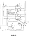
- Fig. 2 is an enlarged view of the main portion of Fig. 1, illustrating in particular an operation control circuit diagram of an arm cylinder portion.
- Fig. 3 is an operation control circuit diagram of a conventional device for operating traveling and working machines of a hydraulic excavator.
- Fig. 1 illustrates an operation control circuit for the device for operating traveling and working machines of a hydraulic excavator according to the present invention, wherein parts corresponding to those of Fig. 3 are indicated by like references.
- Fig. 2 is an enlarged view of the main portion of Fig. 1 which illustrates in particular the operation control circuit associated with the arm cylinder portion.
- a bucket cylinder 6, a leftward-drive motor 7, a boom cylinder 8, a swivel motor 9, an arm cylinder 10 are coupled, via electrical control actuation valves 12, to a hydraulic circuit 3 leading to a variable-capacity hydraulic pump 2 which is driven by an engine 1. Further, the bucket cylinder 6, the leftward-drive motor 7, the boom cylinder 8, a rightward-drive motor 11, and the arm cylinder 10 are coupled, via the electrical control actuation valves 12, to a hydraulic circuit 5 leading to a variable-capacity hydraulic pump 4 which is driven by the engine 1.
- Respective changes of quantities in the actuation of a travel actuating lever 13, a bucket/boom actuating lever 14 and an arm swivel actuating lever 15 each of which comprises an electric lever, are converted to an electric signal which in turn is passed to a controller 16, and a signal outputted from the controller 16 is transmitted to the electrical control actuation valves 12 which permit each of the above-mentioned actuators to be operated.
- Fig. 2 illustrates the relationship between the electrical control actuating valve and the electric/hydraulic circuit related to the arm cylinder 10. The operation of the operating device for traveling and working machines according to the present invention will now be described in detail with reference to Fig. 2.
- the arm swivel actuating lever 15 is actuated so as to cause the arm to damp while a separation-mode switch 17 is set at a standard mode, then the quantity of a change in the actuation of the actuating lever 15 is converted to an electric signal which in turn is passed to the controller 16 from which an input signal is provided to pilot valves 19 and 20.
- pilot valves 19 and 20 meter-in and meter-out side pilot check valves 23, 24, and 25 are opened so that discharge oil supplied from the variable-capacity hydraulic pumps 2 and 4 is permitted to flow into a head-side chamber 10a of the arm cylinder 10, thus causing the arm to be moved in the damping direction.
- pilot valves 21 and 22 are provided with an input signal from the controller 16 so that meter-in and meter-out side pilot check valves 26, 27, and 28 are opened so that discharge oil supplied from the pumps 2 and 4 is permitted to flow into a bottom-side chamber 10b of the arm cylinder 10, thus causing the arm to be moved in the excavating direction.
- the separation mode as set up includes, besides the above-mentioned boom/arm separation mode, a separation mode for the traveling and working machines (the pump 2 is for the working machine, and the pump 4 is for the leftward-drive and rightward-drive motors), a separation mode for the swivel and working machines (the pump 2 is for the swivel motor, and the pump 4 is for the leftward-drive and rightward-drive motors).
- Such separation modes are set up for the purposes of improving the operability during a complex operation, while at the same time preventing speed interference between the actuators.
- the working speed be increased.
- separation mode for the traveling and working machines
- boost/arm separation mode when only the arm is returned without moving the boom during plowing operation
- a separation mode release switch 18 provided on the actuating lever 15 is depressed, and thereupon the electric signal from the separation mode switch 17 is canceled in the controller 16 so that the input signal provided from the controller 16 to the electrical control actuating valves 12 becomes the same as that provided during the normal mode.
- the discharge oil from the pump 2 and that from the pump 4 are merged and permitted to flow into the actuators, thereby increasing the working speed of the actuators.
- the device for operating traveling and working machines of a hydraulic excavator is set at the standard mode during a single operation of the actuators, and is set at the separation mode in accordance with the working contents during a complex operation of the actuators in which operability is an important factor and a speed interference is to be avoided; in case it is required that the working speed be increased during the single operation while working operation is being performed in the separation mode, the operating device can be returned to the standard mode simply by depressing the separation mode release switch so that the working speed is increased; and when the device is to be returned to the separation mode in which the operability is an important factor during the complex operation, it is simply required that the depression of the separation mode release switch be interrupted. In this way, it is possible to greatly enhance the working efficiency of the traveling and working machines of a hydraulic excavator.
- the device for operating traveling and working machines of a hydraulic excavator according to the present invention is suitable for a hydraulic excavator of the type that is required to temporarily increase the working speed while working contents in which the operability is an important factor is being performed during a complex operation.
Landscapes
- Engineering & Computer Science (AREA)
- Mining & Mineral Resources (AREA)
- Civil Engineering (AREA)
- General Engineering & Computer Science (AREA)
- Structural Engineering (AREA)
- Mechanical Engineering (AREA)
- Physics & Mathematics (AREA)
- Fluid Mechanics (AREA)
- Operation Control Of Excavators (AREA)
Abstract
Claims (3)
- Dispositif d'actionnement des machines de déplacement et de travail d'un excavateur hydraulique, comprenant :une pluralité de pompes hydrauliques (2, 4) qui sont entraînées par un moteur (1),une pluralité de tuyaux d'évacuation (3, 5), respectivement prévus à une pompe associée de la pluralité de pompes hydrauliques (2, 4),une pluralité d'électrovannes de manoeuvre (12 ; 23 à 28) pour mettre en oeuvre un dispositif associé d'une pluralité de dispositifs de manoeuvre (6 à 11),un circuit hydraulique pour relier la pluralité de tuyaux d'évacuation (3, 5) et la pluralité de dispositifs de manoeuvre (6 à 11) au moyen des électrovannes de manoeuvre (12 ; 23 à 28),une unité de commande (16) pour commander les mises en oeuvre des vannes de manoeuvre sur la base de signaux de commande,une pluralité de leviers de manoeuvre (13 à 15) pour délivrer les signaux de commande à l'unité de commande (16) de façon à mettre en oeuvre la pluralité de dispositifs de manoeuvre (6 à 11), etun commutateur de mode de séparation (17) pour délivrer un signal de commande à l'unité de commande (16) de façon à sélectionner un mode parmi un mode standard, dans lequel chaque dispositif de manoeuvre (6 à 11) est mis en oeuvre par une pompe ou par une pluralité de pompes hydrauliques reliées (2, 4) en fonction de la quantité de manoeuvre du levier respectif (13 à 15), etun mode de séparation dans lequel des groupes prédéterminés de dispositifs de manoeuvre (6 à 11) sont mis en oeuvre par des pompes hydrauliques prédéterminées (2, 4), de façon indépendante, pour améliorer la capacité de mise en oeuvre pendant la manoeuvre d'une pluralité des leviers (13 à 15),caractérisé en ce queau moins un des leviers de manoeuvre (13 à 15) est muni d'un commutateur de libération de mode de séparation (18), relié à l'unité de commande (16), pour commuter du mode de séparation au mode standard tandis que le commutateur de mode de séparation (17) est dans le mode de séparation,de sorte que, la mise en oeuvre du commutateur de libération de mode de séparation (18) provoque la mise en oeuvre du dispositif de manoeuvre entraîné par le levier de manoeuvre, le commutateur de libération de mode de séparation (18) mis en oeuvre dans le mode standard augmentant la vitesse de travail du dispositif de manoeuvre, et provoque la mise en oeuvre dans le mode de séparation après la libération de la mise en oeuvre du commutateur de libération de mode de séparation (18).
- Dispositif d'actionnement des machines de déplacement et de travail d'un excavateur hydraulique selon la revendication 1, caractérisé en ce que ledit mode de séparation comprend un mode de séparation flèche/bras, un mode de séparation pour les machines de déplacement et de travail, et un mode de séparation pour les machines de pivotement et de travail.
- Dispositif d'actionnement des machines de déplacement et de travail d'un excavateur hydraulique selon la revendication 1, caractérisé en ce que ledit levier de manoeuvre muni dudit commutateur de libération de mode de séparation (18) comprend un levier de manoeuvre de godet-flèche (14) pour manoeuvrer un godet et une flèche dudit excavateur hydraulique et un levier de manoeuvre de bras/pivot (15) pour manoeuvrer un bras et effectuer une manoeuvre de pivotement.
Applications Claiming Priority (3)
| Application Number | Priority Date | Filing Date | Title |
|---|---|---|---|
| JP170413/89 | 1989-06-30 | ||
| JP1170413A JP2583127B2 (ja) | 1989-06-30 | 1989-06-30 | 油圧式掘削機の走行・作業機操作装置 |
| PCT/JP1990/000852 WO1991000396A1 (fr) | 1989-06-30 | 1990-06-29 | Dispositif d'actionnement des machines de deplacement et de travail d'un excavateur hydraulique |
Publications (3)
| Publication Number | Publication Date |
|---|---|
| EP0480037A1 EP0480037A1 (fr) | 1992-04-15 |
| EP0480037A4 EP0480037A4 (en) | 1993-03-31 |
| EP0480037B1 true EP0480037B1 (fr) | 1997-03-05 |
Family
ID=15904466
Family Applications (1)
| Application Number | Title | Priority Date | Filing Date |
|---|---|---|---|
| EP90909838A Expired - Lifetime EP0480037B1 (fr) | 1989-06-30 | 1990-06-29 | Dispositif d'actionnement des machines de deplacement et de travail d'un excavateur hydraulique |
Country Status (5)
| Country | Link |
|---|---|
| EP (1) | EP0480037B1 (fr) |
| JP (1) | JP2583127B2 (fr) |
| KR (1) | KR0143065B1 (fr) |
| DE (1) | DE69030086T2 (fr) |
| WO (1) | WO1991000396A1 (fr) |
Families Citing this family (5)
| Publication number | Priority date | Publication date | Assignee | Title |
|---|---|---|---|---|
| US5547601A (en) * | 1992-09-09 | 1996-08-20 | Jnj Industries, Inc. | CFC-free solvent for solvating solder flux |
| JP3013225B2 (ja) * | 1995-01-11 | 2000-02-28 | 新キャタピラー三菱株式会社 | 吊り作業制御装置 |
| KR100464761B1 (ko) * | 1997-11-29 | 2005-04-06 | 볼보 컨스트럭션 이키프먼트 홀딩 스웨덴 에이비 | 중장비용 유압장치 |
| KR100717922B1 (ko) * | 2003-03-20 | 2007-05-11 | 현대중공업 주식회사 | 붐 고속 상승용 2단 유압장치 |
| DE102009033645A1 (de) * | 2009-07-17 | 2011-01-20 | Robert Bosch Gmbh | Hydraulische Steueranordnung |
Family Cites Families (8)
| Publication number | Priority date | Publication date | Assignee | Title |
|---|---|---|---|---|
| US3960284A (en) * | 1972-10-02 | 1976-06-01 | American Hoist & Derrick Company | Hydraulic backhoe circuitry |
| JPS6343259Y2 (fr) * | 1980-11-10 | 1988-11-11 | ||
| JPS61142234A (ja) * | 1984-12-17 | 1986-06-30 | Sumitomo Heavy Ind Ltd | 油圧ショベル等の建設機械の油圧回路 |
| JPS6258033A (ja) * | 1985-09-07 | 1987-03-13 | Hitachi Constr Mach Co Ltd | 建設機械 |
| US4712376A (en) * | 1986-10-22 | 1987-12-15 | Caterpillar Inc. | Proportional valve control apparatus for fluid systems |
| JPH0823768B2 (ja) * | 1987-01-30 | 1996-03-06 | 株式会社小松製作所 | 操縦制御装置 |
| JPH0745744B2 (ja) * | 1987-09-29 | 1995-05-17 | 日立建機株式会社 | 油圧駆動装置 |
| JPH0826554B2 (ja) * | 1987-12-16 | 1996-03-13 | 株式会社小松製作所 | 油圧堀削作業機の油圧回路装置 |
-
1989
- 1989-06-30 JP JP1170413A patent/JP2583127B2/ja not_active Expired - Fee Related
-
1990
- 1990-06-29 KR KR1019910701918A patent/KR0143065B1/ko not_active Expired - Fee Related
- 1990-06-29 WO PCT/JP1990/000852 patent/WO1991000396A1/fr not_active Ceased
- 1990-06-29 EP EP90909838A patent/EP0480037B1/fr not_active Expired - Lifetime
- 1990-06-29 DE DE69030086T patent/DE69030086T2/de not_active Expired - Fee Related
Also Published As
| Publication number | Publication date |
|---|---|
| DE69030086T2 (de) | 1997-09-11 |
| KR0143065B1 (ko) | 1998-09-15 |
| EP0480037A1 (fr) | 1992-04-15 |
| KR920702744A (ko) | 1992-10-06 |
| EP0480037A4 (en) | 1993-03-31 |
| WO1991000396A1 (fr) | 1991-01-10 |
| JP2583127B2 (ja) | 1997-02-19 |
| DE69030086D1 (de) | 1997-04-10 |
| JPH0336336A (ja) | 1991-02-18 |
Similar Documents
| Publication | Publication Date | Title |
|---|---|---|
| JP3550260B2 (ja) | アクチュエータ作動特性制御装置 | |
| EP0783057B1 (fr) | Système hydraulique de commande pour machines de chantier | |
| EP3647500B1 (fr) | Système et procédé de commande de déplacement pour machines de construction | |
| EP2660478B1 (fr) | Système de commande hydraulique d'entraînement combiné flèche/pivot pour machine de construction | |
| JP2000145720A (ja) | 作業機械における油圧制御装置 | |
| CN114207293B (zh) | 建筑机械的液压系统 | |
| JPS6225882B2 (fr) | ||
| JP2581858Y2 (ja) | ロードセンシングシステムにおける複数ポンプの分・合流切換装置 | |
| KR100797315B1 (ko) | 굴삭기의 주행 및 프론트작업의 복합작업용 유압제어장치 | |
| US11655613B2 (en) | Hydraulic system of construction machine | |
| EP0480037B1 (fr) | Dispositif d'actionnement des machines de deplacement et de travail d'un excavateur hydraulique | |
| JPH04194405A (ja) | ロードセンシングシステムにおける複数ポンプの分・合流切換装置 | |
| JPH0216416B2 (fr) | ||
| JPH08219107A (ja) | 油圧機械の油圧再生装置 | |
| EP3835598A1 (fr) | Engin de chantier | |
| JPH086354B2 (ja) | 油圧式掘削機の油圧回路 | |
| JP2716607B2 (ja) | 建設機械の油圧回路 | |
| JP3205910B2 (ja) | 単一可変容量ポンプによる複数アクチュエータの作動制御装置 | |
| JP2002317471A (ja) | 油圧ショベルの油圧制御回路 | |
| JP2757009B2 (ja) | 建設機械の微操作制御方法 | |
| KR19980063238A (ko) | 중장비의 다목적 유압제어장치 | |
| JPH0621462B2 (ja) | 土木建設機械の油圧回路 | |
| JPH10299027A (ja) | 建設機械の油圧駆動装置 | |
| JPH09156875A (ja) | 建設機械の油圧制御装置 | |
| KR0138161Y1 (ko) | 작업조건에 따라 액츄에이터의 속도 조정이 가능한 유압회로 |
Legal Events
| Date | Code | Title | Description |
|---|---|---|---|
| PUAI | Public reference made under article 153(3) epc to a published international application that has entered the european phase |
Free format text: ORIGINAL CODE: 0009012 |
|
| 17P | Request for examination filed |
Effective date: 19920109 |
|
| AK | Designated contracting states |
Kind code of ref document: A1 Designated state(s): DE FR GB |
|
| A4 | Supplementary search report drawn up and despatched |
Effective date: 19930208 |
|
| AK | Designated contracting states |
Kind code of ref document: A4 Designated state(s): DE FR GB |
|
| 17Q | First examination report despatched |
Effective date: 19941216 |
|
| GRAG | Despatch of communication of intention to grant |
Free format text: ORIGINAL CODE: EPIDOS AGRA |
|
| GRAH | Despatch of communication of intention to grant a patent |
Free format text: ORIGINAL CODE: EPIDOS IGRA |
|
| GRAH | Despatch of communication of intention to grant a patent |
Free format text: ORIGINAL CODE: EPIDOS IGRA |
|
| GRAA | (expected) grant |
Free format text: ORIGINAL CODE: 0009210 |
|
| AK | Designated contracting states |
Kind code of ref document: B1 Designated state(s): DE FR GB |
|
| PG25 | Lapsed in a contracting state [announced via postgrant information from national office to epo] |
Ref country code: FR Effective date: 19970305 |
|
| REF | Corresponds to: |
Ref document number: 69030086 Country of ref document: DE Date of ref document: 19970410 |
|
| PGFP | Annual fee paid to national office [announced via postgrant information from national office to epo] |
Ref country code: GB Payment date: 19970620 Year of fee payment: 8 |
|
| PGFP | Annual fee paid to national office [announced via postgrant information from national office to epo] |
Ref country code: DE Payment date: 19970704 Year of fee payment: 8 |
|
| EN | Fr: translation not filed | ||
| PLBE | No opposition filed within time limit |
Free format text: ORIGINAL CODE: 0009261 |
|
| STAA | Information on the status of an ep patent application or granted ep patent |
Free format text: STATUS: NO OPPOSITION FILED WITHIN TIME LIMIT |
|
| 26N | No opposition filed | ||
| PG25 | Lapsed in a contracting state [announced via postgrant information from national office to epo] |
Ref country code: GB Free format text: LAPSE BECAUSE OF NON-PAYMENT OF DUE FEES Effective date: 19980629 |
|
| GBPC | Gb: european patent ceased through non-payment of renewal fee |
Effective date: 19980629 |
|
| PG25 | Lapsed in a contracting state [announced via postgrant information from national office to epo] |
Ref country code: DE Free format text: LAPSE BECAUSE OF NON-PAYMENT OF DUE FEES Effective date: 19990401 |