EP0480119B1 - Verfahren und Vorrichtung zum Steuern von Raffstores - Google Patents
Verfahren und Vorrichtung zum Steuern von Raffstores Download PDFInfo
- Publication number
- EP0480119B1 EP0480119B1 EP91104133A EP91104133A EP0480119B1 EP 0480119 B1 EP0480119 B1 EP 0480119B1 EP 91104133 A EP91104133 A EP 91104133A EP 91104133 A EP91104133 A EP 91104133A EP 0480119 B1 EP0480119 B1 EP 0480119B1
- Authority
- EP
- European Patent Office
- Prior art keywords
- slats
- angle
- slat
- photodiodes
- photocell
- Prior art date
- Legal status (The legal status is an assumption and is not a legal conclusion. Google has not performed a legal analysis and makes no representation as to the accuracy of the status listed.)
- Expired - Lifetime
Links
- 229920003023 plastic Polymers 0.000 claims description 2
- 239000000463 material Substances 0.000 claims 1
- 230000005855 radiation Effects 0.000 claims 1
- 230000001419 dependent effect Effects 0.000 abstract description 4
- 238000012216 screening Methods 0.000 abstract description 2
- 241000446313 Lamella Species 0.000 description 9
- 230000037072 sun protection Effects 0.000 description 4
- 230000008878 coupling Effects 0.000 description 2
- 238000010168 coupling process Methods 0.000 description 2
- 238000005859 coupling reaction Methods 0.000 description 2
- 230000001960 triggered effect Effects 0.000 description 2
- 230000001154 acute effect Effects 0.000 description 1
- 238000004378 air conditioning Methods 0.000 description 1
- 230000001276 controlling effect Effects 0.000 description 1
- 238000013500 data storage Methods 0.000 description 1
- 238000010586 diagram Methods 0.000 description 1
- 230000000694 effects Effects 0.000 description 1
- 230000004313 glare Effects 0.000 description 1
- 230000003760 hair shine Effects 0.000 description 1
- 238000010438 heat treatment Methods 0.000 description 1
- 238000009434 installation Methods 0.000 description 1
- 230000003993 interaction Effects 0.000 description 1
- 238000005259 measurement Methods 0.000 description 1
- 229920003229 poly(methyl methacrylate) Polymers 0.000 description 1
- 239000004926 polymethyl methacrylate Substances 0.000 description 1
- 230000001105 regulatory effect Effects 0.000 description 1
- 230000002441 reversible effect Effects 0.000 description 1
- 239000013589 supplement Substances 0.000 description 1
Images

Classifications
-
- E—FIXED CONSTRUCTIONS
- E06—DOORS, WINDOWS, SHUTTERS, OR ROLLER BLINDS IN GENERAL; LADDERS
- E06B—FIXED OR MOVABLE CLOSURES FOR OPENINGS IN BUILDINGS, VEHICLES, FENCES OR LIKE ENCLOSURES IN GENERAL, e.g. DOORS, WINDOWS, BLINDS, GATES
- E06B9/00—Screening or protective devices for wall or similar openings, with or without operating or securing mechanisms; Closures of similar construction
- E06B9/24—Screens or other constructions affording protection against light, especially against sunshine; Similar screens for privacy or appearance; Slat blinds
- E06B9/26—Lamellar or like blinds, e.g. venetian blinds
- E06B9/28—Lamellar or like blinds, e.g. venetian blinds with horizontal lamellae, e.g. non-liftable
- E06B9/30—Lamellar or like blinds, e.g. venetian blinds with horizontal lamellae, e.g. non-liftable liftable
- E06B9/32—Operating, guiding, or securing devices therefor
-
- Y—GENERAL TAGGING OF NEW TECHNOLOGICAL DEVELOPMENTS; GENERAL TAGGING OF CROSS-SECTIONAL TECHNOLOGIES SPANNING OVER SEVERAL SECTIONS OF THE IPC; TECHNICAL SUBJECTS COVERED BY FORMER USPC CROSS-REFERENCE ART COLLECTIONS [XRACs] AND DIGESTS
- Y02—TECHNOLOGIES OR APPLICATIONS FOR MITIGATION OR ADAPTATION AGAINST CLIMATE CHANGE
- Y02A—TECHNOLOGIES FOR ADAPTATION TO CLIMATE CHANGE
- Y02A30/00—Adapting or protecting infrastructure or their operation
- Y02A30/24—Structural elements or technologies for improving thermal insulation
-
- Y—GENERAL TAGGING OF NEW TECHNOLOGICAL DEVELOPMENTS; GENERAL TAGGING OF CROSS-SECTIONAL TECHNOLOGIES SPANNING OVER SEVERAL SECTIONS OF THE IPC; TECHNICAL SUBJECTS COVERED BY FORMER USPC CROSS-REFERENCE ART COLLECTIONS [XRACs] AND DIGESTS
- Y02—TECHNOLOGIES OR APPLICATIONS FOR MITIGATION OR ADAPTATION AGAINST CLIMATE CHANGE
- Y02B—CLIMATE CHANGE MITIGATION TECHNOLOGIES RELATED TO BUILDINGS, e.g. HOUSING, HOUSE APPLIANCES OR RELATED END-USER APPLICATIONS
- Y02B80/00—Architectural or constructional elements improving the thermal performance of buildings
Definitions
- the invention relates to a device for controlling at least one venetian blind with a curtain consisting of slats, which can be moved between a gathered position and a shading position and whose slats are reversible by a motor and adjustable in the shielding angle by means of a photo sensor connected to a slat, the photosensor consists of two photodiodes arranged one behind the other in relation to the window in the direction from the outside to the inside in such a way that, due to uneven irradiation, they register a certain deviation of the angle of inclination of the incident sun rays from a normal on the base of the lamella.
- sun protection plays an important role in preventing excessive heating of the work rooms, saving energy in the presence of an air conditioning system and providing glare protection at monitor work stations. It has so far been customary to centrally control the external venetian blinds of an office building facade using sensors installed on the roof of the building.
- the disadvantage arises that, depending on the circumstances of the individual case, different windows of a facade are fully exposed to sunlight, while other windows of the same facade lie in the shadow of other buildings or parts of buildings.
- the problem of different lighting of the windows of a facade is made even more difficult by the fact that the situation changes with the movement of the sun over the course of a day depending on the season.
- Another shortcoming of centrally controlled external venetian blinds is that after triggering the lowering movement at a certain basic brightness, the low command for all external venetian blinds remains for a predetermined time before a slat opening pulse is triggered after this predetermined downtime. If curtains of different lengths are on a facade, the run-down time of the longest curtain must generally be set. The rooms with shorter runtimes remain darkened for an unnecessarily long time until the opening impulse comes. The opening angle of the slats then set can be completely wrong depending on the time of day and the season and the special position of a window.
- EP-A1-0199931 also describes a sun protection device consisting of a plurality of transparent slats provided with prisms on the underside, in which the inclination of the slats is controlled by a photo sensor attached to a slat.
- the photosensor is also provided with a towering, shadow-forming web, it can be attached directly to a slat because the slats are not gathered.
- two photodiodes are mounted on different inclined prism surfaces on the underside of a lamella, the reflective effect of the prisms being used to determine the correct position of the lamella.
- this design cannot be applied to blinds with opaque slats.
- the invention has for its object to provide a control device of the type mentioned, which can be installed in a space-saving manner and by means of which, in particular in buildings whose window surfaces in a facade are exposed to different incidence of light, the most uniform possible shading of the rooms is achieved.
- the photo sensor sits in an opening in the lamella and the photo diodes form an angle with one another, and that a further photo sensor is present which, when a certain basic brightness is reached, a control signal for moving the curtain by means of the motor the gathered position in a shading position.
- the new control device can also be realized in the presence of a central control device, which ensures a uniform appearance of a facade and in a known manner, for. B. interacts with a wind sensor to pull up the venetian blind at a certain wind speed.
- the invention does not affect these higher-level tasks of a central control device, but advantageously supplements them by individually regulating the incidence of light in the shading position.
- the new device can be used both for external venetian blinds (blinds) with horizontal as well as those with vertical slats (vertical blinds).
- the optimal control of the shielding angle can begin because of the proposed individual control of the individual venetian blinds immediately after the lower position has been reached, regardless of the fact that longer curtains on the same facade still take a longer time to reach the lower position and then in the shielding angle to be set.
- the proposal according to the invention is also to be understood in the sense that the external venetian blinds of a facade normally move up and down in a centrally controlled manner, but a single external venetian blind can also be lowered or raised individually if the basic brightness exceeds or falls below certain threshold values.
- the photosensor tracks the sun when the position of the sun changes, and the necessary movement of the photosensor can be brought about by the reversing drive of the slats.
- a special feature is the proposed fastening of the photosensor in an opening in a lamella and the arrangement of two photodiodes which form an angle with one another. These can be arranged approximately roof-shaped or V-shaped with respect to the base area of the lamella, so that the ones of them generated control voltages are only the same size if they are both exposed to the same angle with sun rays, d. H. the sun shines perpendicular to the base of the slat. Due to this fact, the current position of the sun can be determined by swiveling the slat and the slat can be set in the optimal shielding angle.
- the proposed control device permits automatic control of the curtain, since according to the invention there is a further photo sensor which generates a control pulse when a certain basic brightness is reached.
- the further photosensor is in front of or next to the curtain, e.g. B. on a housing or guide part of the venetian blind, to fasten and has several, expediently three, aligned to different directions photo diodes, which together detect the incidence of light over the angular range of 180 ° in front of the venetian blind.
- control devices are used in the last-mentioned embodiment, one can in principle without a central control device get along.
- the lowering and raising of the venetian blind is controlled in this case by the additional photo sensor according to the respective basic brightness, and in the lowered state, the sun search sensor mounted on a slat takes over the control of the shielding angle of the slats.
- the lowering and pulling up of all external venetian blinds of a facade is controlled centrally.
- the additional photo sensors installed there only ensure that the relevant venetian blinds are raised or lowered depending on the situation, if certain window brightness values are exceeded or undershot.
- the said sun search sensor already registers small angular deviations of the incident sun rays from the normal on the base of the slat and then ensures a change in the shielding angle in the direction that the sun rays practically always fall perpendicular to the base of the slat .
- the invention can also be carried out in such a way that a certain height angle between the incident sun rays and the normal is constantly maintained on the base of the lamella in order to let in a little more light than in the case of lamellae directed perpendicular to the incident sun rays.
- the correction movement controlled by the control device serves to maintain the predetermined angle between the incident sun rays and the base area of the slat despite the changing position of the sun.
- the base area is the maximum projection area of a slat.
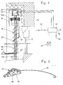
- a photosensor 22 is attached to one of the slats 18, which is able to determine whether the sunlight falling obliquely from above is perpendicular to the Base area of the slats or in which direction the incident sun rays in a vertical transverse plane through the slats deviate from the normal on the base area of the slats.
- the basic structure of the photo sensor 22 is discussed in more detail below in connection with FIG. 2.
- a further photo sensor 24 is mounted. He can e.g. B. on the masonry next to the fixed opening, on a guide of the slats 18 or on the housing 16. This further photo sensor 24 determines the basic brightness and controls the lowering and raising of the venetian blind 14. It is explained in more detail in connection with FIG. 3.
- the photosensor 22 is preferably inserted into an opening in the vicinity of the outer longitudinal edge of a lamella 18. It consists in the embodiment of FIG. 2 of two in transparent plastic, for. B. acrylic glass, enclosed photodiodes 26, 28, which are arranged roof-shaped at a certain gable angle. It can be seen that the control voltage of the two photodiodes 26, 28 is only of the same magnitude if both are struck by the sun's rays with the same intensity, and this in turn is only the case if the sun's rays are parallel to the bisector of the gable arrangement of the photodiodes 26 , 28 come up.
- the control voltage of one of the two photodiodes 26, 28 is lower than that of the other, it can be concluded that the sun's rays are incident at an acute angle to the said bisector and that the photodiode, which generates the smaller control voltage, is directed towards that must be pivoted towards the other photodiode in order to achieve the equilibrium state again, in which both photodiodes are irradiated uniformly and preferably the bases of the parallel slats 18 are aligned perpendicular to the incident sun rays.
- the further photo sensor 24 for determining the basic brightness shown in FIG. 3 A in plan view and in cross section in FIG. 3 B, consists of three photodiodes 34, 36, 38 arranged next to one another, each pointing at different angles and at an intermediate angle of 60 ° 3 B are inclined at an angle of 35 ° to the vertical. Since each of the photodiodes 34, 36, 38 according to FIG. 3 C each has a recording area of approximately 60 °, the total the basic brightness is recorded over the entire area of 180 ° in front of a building facade.
- the connecting lines, designated 40, of the photo sensor 22 and the connecting lines 42 of the photo sensor 24 are guided along the guide rails or the curtain of the external venetian blind to a distribution box 44 installed in or on its upper box. This is connected by means of a plug coupling to a motor control unit 46, which is installed in a suitable place in the building, preferably not too far from the venetian blind 14.
- a conventional button 48 for individual operation is also connected to the engine control unit 46. It allows the slats of the external venetian blind to be adjusted by hand, e.g. B. completely darken a room because of a film screening.
- connection 50 to a central control device a serial interface 50 for connection to a computer and data storage device and a mains connection 52 for supplying the motor 20 with an operating voltage of 220 volts and that interacting with the photo sensors 22 and 24 are also indicated on the motor control unit 46
- Control device with a control voltage of 24 volts.
- the engine control unit 46 is connected to the engine 20 via a plug coupling in order to control it in accordance with the various control inputs of the engine control unit 46.
- a trigger signal for lowering the venetian blind can come either from the connection 50 from a central control device or, given a certain basic brightness, from the photo sensor 24.
- the control of the shielding angle of the slats takes place 18 by means of the photo sensor 22, regardless of whether other external venetian blinds of the same facade, which were lowered at the same time, have not yet reached their low position because their curtain is longer.
- the control of the shielding angle of the slats 18 by means of the photo sensor 22 then remains permanently effective and changes the position of the slats in accordance with the changing position of the sun until the Venetian blind is pulled up and gathered again by a start-up signal triggered by the central control device or the photo sensor 24.
- the described control device offers, through the interaction of the direction-dependent photo sensor 22 and the further photo sensor 24 for the basic brightness, the possibility that a number of venetian blinds in the lowered state, in which they are normally controlled by the direction-dependent photo sensor 22, temporarily by the photo sensor 24 in a horizontal Slat position can be reversed when they reach the shadow of a cloud.
- the direction-dependent photo sensor 22 again takes over the control of the shielding angle of the slats 18 and ensures the adjustment from the horizontal position to the optimal shielding position corresponding to the position of the sun.
- the manual adjustment of the slat angle by means of the button 48 can be integrated into the control described above in such a way that the automatic adjustment of the shielding angle by means of the photo sensor 22 does not occur if the curtain has been manually lowered by pressing the button 48 twice and the slats in the closed position were brought.
- the automatic system then assumes that it is a deliberate obscuration, e.g. B. for a slide show. If, on the other hand, the curtain had been manually lowered by pressing the button 48 once, the slats are set to a certain angle from Z. B. 38 ° and the optimum angle is only adjusted by the sun search sensor 22 when a certain brightness is exceeded. Even if the slat position is intervened manually after the automatic search function has been activated, the automatic sun search function switches itself off. It only comes back into action when a main direction of travel is briefly activated and then stopped.
- the control device has been described above in connection with the control of a single venetian blind. It is understood that if a plurality of windows of a facade are basically exposed to the same lighting conditions at any time of the year and day and also in the assigned rooms of the building essentially the same lighting requirements are imposed, a single sun sensor 22 on a slat 18 one of the external venetian blinds and a single further photo sensor 24 next to one of the windows are sufficient to control all external venetian blinds connected in parallel in their controls.
- the measurement and control signals can be transmitted wirelessly from the photo sensors to the engine control unit and from there to the engine.
- a radio connection can also exist to the central control device. Messages via the interface 50 can also be error messages that enable the error to be identified and localized. If necessary, phototransistors could also replace photodiodes.
Landscapes
- Engineering & Computer Science (AREA)
- Structural Engineering (AREA)
- Architecture (AREA)
- Civil Engineering (AREA)
- Blinds (AREA)
- Selective Calling Equipment (AREA)
Description
- Die Erfindung betrifft eine Vorrichtung zum Steuern wenigstens eines Raffstores mit einem aus Lamellen bestehenden Behang, der zwischen einer gerafften Stellung und einer Verschattungsstellung bewegbar ist und dessen Lamellen durch einen Motor wendbar und mittels eines mit einer Lamelle verbundenen Fotosensors im Abschirmwinkel einstellbar sind, wobei der Fotosensor aus zwei mit Bezug auf das Fenster in Richtung von auβen nach innen derart hintereinander angeordneten Fotodioden besteht, daß sie infolge ungleichmäßiger Bestrahlung eine bestimmte Abweichung des Neigungswinkels der einfallenden Sonnenstrahlen von einer Normalen auf der Grundfläche der Lamelle registrieren.
- Bei modernen Bürogebäuden spielt der Sonnenschutz eine wichtige Rolle, um übermäßige Erwärmung der Arbeitsräume zu verhindern, bei Vorhandensein einer Klimaanlage Energie einzusparen und an Bildschirm-Arbeitsplätzen für Blendschutz zu sorgen. Es ist bisher üblich, die Raffstore einer Bürohausfassade mittels auf dem Dach des Gebäudes installierter Sensoren zentral zu steuern. Dabei tritt der Nachteil auf, daß je nach Umständen des Einzelfalls verschiedener Fenster einer Fassade voll dem Sonnenlicht ausgesetzt sind, während andere Fenster derselben Fassade im Schatten anderer Gebäude oder Gebäudeteile liegen. Das Problem der unterschiedlichen Beleuchtung der Fenster einer Fassade wird noch dadurch erschwert, daß sich die Situation mit der Wanderung der Sonne im Verlauf eines Tages je nach Jahreszeit verändert. Es sind in der letzten Zeit Versuche unternommen worden, bei zentral gesteuerten Sonnenschutzanlagen durch aufwendige Verschattungsdiagramme und astronomische Uhren die Funktion der Steuerungsautomatik zu verbessern. Dadurch kann jedoch der grundlegende Nachteil, daß die besonderen Beleuchtungsverhältnisse eines speziellen Fensters unberücksichtigt bleiben, nicht behoben werden.
- Ein weiterer Mangel zentral gesteuerter Raffstore besteht darin, daß nach dem Auslösen der Absenkbewegung bei einer bestimmten Grundhelligkeit zunächst über eine vorgegebene Zeit das Tief-Kommando für alle Raffstore bestehen bleibt, bevor nach Ablauf dieser vorbestimmten Tieflaufzeit ein Lamellen-Öffnungsimpuls ausgelöst wird. Sind unterschiedlich lange Behänge an einer Fassade, so muß im allgemeinen die Tieflaufzeit des längsten Behanges eingestellt werden. Die Räume mit kürzeren Laufzeiten bleiben unnötig lange abgedunkelt, bis der Öffnungsimpuls kommt. Der daraufhin eingestellte Öffnungswinkel der Lamellen kann dann je nach Tages- und Jahreszeit und der besonderen Lage eines Fensters völlig falsch sein.
- Es ist aus der US-A-4,773,733 eine Steuervorrichtung der eingangs genannten Art bekannt, bei welcher ein Lamellenbehang von Hand in Verschattungsstellung herabgelassen und später wieder in die geraffte Stellung hochgezogen wird. An einer der Lamellen ist ein Fotosensor angebracht, der aus zwei hintereinander in derselben Ebene angeordneten Fotodioden besteht, die durch einen zwischen ihnen aufragenden Steg getrennt sind, welcher je nach der Stellung der Lamellen und der Einfallrichtung der Sonnenstrahlen die eine oder die andere Fotodiode stärker beschattet. Wegen der dadurch bedingten großen Höhe des Fotosensors muß er derart an einer Seitenkante der ihn tragenden Lamelle befestigt sein, daß er über diese hinaus nach außen vorsteht und somit die notwendige Einbautiefe, z. B. zwischen zwei Fensterscheiben, und die Gehäusetiefe vergrößert. Da die Jalousie manuell herabgelassen und hochgezogen wird und die Steuervorrichtung nur die Schrägstellung der Lamellen steuert, eignet sie sich nicht für Bürogebäude, bei denen ein gleichmäßiges Aussehen der Fassade angestrebt wird.
- Eine aus einer Vielzahl von transparenten, auf der Unterseite mit Prismen versehenen Lamellen bestehende Sonnenschutzeinrichtung, bei welcher die Neigung der Lamellen durch einen an einer Lamelle befestigten Fotosensor gesteuert wird, ist auch in der EP-A1-0199931 beschrieben. Obgleich der Fotosensor ebenfalls mit einem hoch aufragenden, Schatten bildenden Steg versehen ist, kann er in diesem Fall unmittelbar auf einer Lamelle angebracht sein, weil die Lamellen nicht gerafft werden. Bei einer ähnlichen Sonnenschutzeinrichtung gemäß EP-B-0 251 311 werden zwei Fotodioden auf unterschiedlichen geneigten Prismenflächen auf der Unterseite einer Lamelle angebracht, wobei man die Reflexionswirkung der Prismen für die Feststellung der richtigen Lage der Lamelle ausnutzt. Diese Konstruktion läßt sich jedoch nicht auf Jalousien mit undurchsichtigen Lamellen übertragen.
- Weitere bekannte Vorrichtungen sehen das Absenken des Behangs durch Handsteuerung und die Ausrichtung der Lamellen mittels eines fest im Raum angebrachten Lichtsensors (US-A-3,646,985, US-A-4,644,990) oder ganz allgemein einen auf die Helligkeit und den Sonnenwinkel ansprechenden Signalgeber vor, der die Stellung des Behangs und der Lamellen steuert, wobei Art und Ort der Anbringung des Signalgebers offen bleiben (DE-A-26 27 219).
- Der Erfindung liegt die Aufgabe zugrunde, eine Steuervorrichtung der eingangs genannten Art zu schaffen, welche sich raumsparend montieren läßt und mittels welcher insbesondere bei Gebäuden, deren Fensterflächen in einer Fassade unterschiedlichem Lichteinfall ausgesetzt sind, eine möglichst gleichmäßige Beschattung der Räume erzielt wird.
- Zur Lösung der vorstehenden Aufgabe wird erfindungsgemäß vorgeschlagen, daß der Fotosensor in einer Durchbrechung der Lamelle sitzt und die Fotodioden miteinander einen Winkel bilden, und daß ein weiterer Fotosensor vorhanden ist, welcher bei Erreichen einer bestimmten Grundhelligkeit ein Steuersignal zur Bewegung des Behangs mittels des Motors aus der gerafften Stellung in eine Verschattungsstellung erzeugt.
- Die neue Steuervorrichtung läßt sich auch bei Vorhandensein einer zentralen Steuereinrichtung realisieren, die für ein gleichmäßiges Erscheinungsbild einer Fassade sorgt und in bekannter Weise z. B. mit einem Windsensor zusammenwirkt, um bei einer bestimmten Windgeschwindigkeit die Raffstore hochzuziehen. Die Erfindung läßt diese übergeordneten Aufgaben einer zentralen Steuereinrichtung unberührt, ergänzt sie aber in vorteilhafter Weise durch eine individuelle Regelung des Lichteinfalls in Verschattungsstellung. Die neue Vorrichtung ist anwendbar sowohl bei Raffstores (Jalousien) mit waagerechten als auch bei solchen mit senkrechten Lamellen (Vertikaljalousien).
- Die optimale Steuerung des Abschirmwinkels kann wegen der vorgeschlagenen individuellen Steuerung der einzelnen Raffstore sofort beginnen, nachdem jeweils die Tiefstellung erreicht worden ist, ohne Rücksicht darauf, daß längere Behänge an derselben Fassade noch eine längere Zeit benötigen, um die Tiefstellung zu erreichen und dann im Abschirmwinkel eingestellt zu werden.
- Der erfindungsgemäße Vorschlag ist aber auch in dem Sinne zu verstehen, daß die Raffstore einer Fassade zwar normalerweise zentral gesteuert auf- und abfahren, jedoch bei Über- oder Unterschreiten bestimmter Grenzwerte der Grundhelligkeit ein einzelner Raffstore auch einzeln abgesenkt oder hochgezogen werden kann.
- Die Einfachheit der vorgeschlagenen Steuervorrichtung resultiert daraus, daß in an sich bekannter Weise der Fotosensor bei sich änderndem Sonnenstand der Sonne nachgeführt wird, wobei die hierzu notwendige Bewegung des Fotosensors durch den Wendeantrieb der Lamellen bewirkt werden kann. Eine Besonderheit stellt dabei die vorgeschlagene Befestigung des Fotosensors in einer Durchbrechung einer Lamelle und die Anordnung von zwei miteinander einen Winkel bildenden Fotodioden dar. Diese können etwa dach- oder V-förmig mit Bezug auf die Grundfläche der Lamelle angeordnet sein, so daß die von ihnen erzeugten Steuerspannungen nur dann gleich groß sind, wenn sie beide unter demselben Winkel mit Sonnenstrahlen beaufschlagt werden, d. h. die Sonne senkrecht auf die Grundfläche der Lamelle scheint. Aufgrund dieser Tatsache läßt sich durch Verschwenken der Lamelle der aktuelle Sonnenstand ermitteln und die Lamelle im optimalen Abschirmwinkel einstellen.
- Der in einer Lamelle sitzende, infolge der dach- oder V-förmigen Anordnung der Fotodioden verhaltnismäßig flache Fotosensor befindet sich im gerafften Zustand des Behangs zwischen den Lamellen, so daß er von diesen überdeckt und funktionsunfähig ist. Dennoch erlaubt die vorgeschlagene Steuervorrichtung eine automatische Steuerung des Behangs, da erfindungsgemäß ein weiterer Fotosensor vorhanden ist, welcher bei Erreichen einer bestimmten Grundhelligkeit einen Steuerimpuls erzeugt. Vorzugsweise ist der weitere Fotosensor vor oder neben dem Behang, z. B. an einem Gehäuse oder Führungsteil des Raffstores, zu befestigen und hat mehrere, zweckmässigerweise drei, auf unterschiedliche Himmelsrichtungen ausgerichtete Fotodioden, welche zusammen den Lichteinfall über den Winkelbereich von 180° vor dem Raffstore erfassen.
- Wenn Steuervorrichtungen in der zuletzt genannten Ausführung verwendet werden, kann man grundsätzlich ohne zentrale Steuervorrichtung auskommen. Das Absenken und Hochziehen des Raffstores wird in diesem Fall von dem weiteren Fotosensor entsprechend der jeweiligen Grundhelligkeit gesteuert, und im herabgelassenen Zustand übernimmt der an einer Lamelle montierte Sonnensuch-Sensor die Steuerung des Abschirmwinkels der Lamellen. Wie bereits erwähnt, kann aber auch das Zusammenwirken mit einer zentralen Steuereinrichtung sinnvoll sein, um soweit wie möglich ein gleichmäßiges Aussehen der Fassade zu erhalten und die Raffstore vor Windschäden zu bewahren. Bei einer solchen kombinierten Steuerung wird zunächst das Herablassen und Hochziehen sämtlicher Raffstore einer Fassade zentral gesteuert. Nur wenn an einzelnen Fenstern bestimmte Grenzwerte der Grundhelligkeit über- oder unterschritten werden, sorgen die dort angebrachten weiteren Fotosensoren dafür, daß die betreffenden Raffstore situationsgerecht hochgezogen oder abgesenkt werden.
- Es kann vorgesehen sein, daß der genannte Sonnensuch-Sensor schon geringe Winkelabweichungen der einfallenden Sonnenstrahlen von der Normalen auf der Grundfläche der Lamelle registriert und dann für eine Änderung des Abschirmwinkels in der Richtung sorgt, daß die Sonnenstrahlen praktisch immer senkrecht auf die Grundfläche der Lamelle fallen. Die Erfindung läßt sich aber auch so ausführen, daß ständig ein bestimmter Höhenwinkel zwischen den einfallenden Sonnenstrahlen und der Normalen auf der Grundfläche der Lamelle aufrecht erhalten wird, um etwas mehr Licht in einen Raum einzulassen als bei senkrecht zu den einfallenden Sonnenstrahlen gerichteten Lamellen. Die von der Steuervorrichtung gesteuerten Korrekturbewegung dienen im letztgenannten Fall dazu, den vorbestimmten Winkel zwischen den einfallenden Sonnenstrahlen und der Grundfläche der Lamelle trotz sich ändernden Sonnenstandes beizubehalten. Als Grundfläche wird die maximale Projektionsfläche einer Lamelle verstanden.
- Die Erfindung wird nachstehend anhand von in der Zeichnung dargestellten Ausführungsbeispielen näher erläutert. Es zeigen:
- Fig. 1
- eine vereinfachte Seitenansicht eines Raffstores mit zugeordneten Fotosensoren;
- Fig. 2
- einen Querschnitt durch eine Lamelle des Raffstores nach Fig. 1 mit einem daran montierten Fotosensor;
- Fig. 3 A, B, C
- verschieden Ansichten eines neben dem Raffstore nach Fig. 1 montierten Fotosensors zur Ermittlung der Grundhelligkeit.
- In Fig. 1 ist ein Ausschnitt einer Gebäudewand 10 mit einem Fenster 12 und einem außenseitig davor angeordneten Raffstore 14 dargestellt. Letzterer ist der Einfachheit halber sowohl in der hochgezogenen, gerafften Position (bei 14a) als auch in der herabgelassenen Position (siehe bei 14b) gezeigt. In der Position 14a ist der Raffstore 14 in einem Gehäuse 16 aufgenommen. Das Hoch- und Tieffahren des Raffstores 14 sowie das Wenden der Lamellen 18 seines Behangs erfolgt in bekannter Weise mittels eines Elektromotors 20 und eines Wendegetriebes, wie es z. B. in der DE-OS 36 25 365 beschrieben ist. Grundsätzlich ist die nachstehend beschriebene Besonderheit unabhängig von der Anzahl, Form und Größe der Lamellen 18 sowie deren Antrieb und Führung. Wesentlich ist nur, daß sich die Lamellen 18 des Behangs mittels eines steuerbaren motorischen Antriebs wenden, d. h. auf verschiedene Abschirmwinkel einstellen lassen.
- Gemäß Fig. 1 ist an einer der Lamellen 18 ein Fotosensor 22 befestigt, welcher in der Lage ist festzustellen, ob das schräg von oben einfallende Sonnenlicht senkrecht auf die Grundfläche der Lamellen trifft bzw. in welcher Richtung die einfallenden Sonnenstrahlen in einer senkrechten Querebene durch die Lamellen von der Normalen auf der Grundfläche der Lamellen abweichen. Auf den grundsätzlichen Aufbau des Fotosensors 22 wird nachstehend im Zusammenhang mit Fig. 2 noch näher eingegangen.
- Neben dem Raffstore 14 ist noch ein weiterer Fotosensor 24 montiert. Er kann z. B. am Mauerwerk neben der Festeröffnung, an einer Führung der Lamellen 18 oder am Gehäuse 16 befestigt sein. Dieser weitere Fotosensor 24 ermittelt die Grundhelligkeit und steuert das Absenken und Hochziehen des Raffstores 14. Er wird im Zusammenhang mit Fig. 3 näher erläutert.
- Der Fotosensor 22 wird gemäß Fig. 2 vorzugsweise nahe der äußeren Längskante einer Lamelle 18 in eine Durchbrechung derselben eingesetzt. Er besteht im Ausführungsbeispiel nach Fig. 2 aus zwei in transparentem Kunststoff, z. B. Acrylglas, eingeschlossenen Fotodioden 26, 28, die unter einem bestimmten Giebelwinkel dachförmig angeordnet sind. Es ist ersichtlich, daß die Steuerspannung der beiden Fotodioden 26, 28 nur dann gleich groß ist, wenn beide mit derselben Intensität von den Sonnenstrahlen getroffen werden, und dies wiederum ist nur dann der Fall, wenn die Sonnenstrahlen parallel zur Winkelhalbierenden der Giebelanordnung der Fotodioden 26, 28 einfallen. Ist dagegen die Steuerspannung einer der beiden Fotodioden 26, 28 niedriger als die der anderen, so läßt sich daraus schließen, daß die Sonnenstrahlen unter einem spitzen Winkel zu der genannten Winkelhalbierenden einfallen und daß die Fotodiode, welche die kleinere Steuerspannung erzeugt, in Richtung zu der anderen Fotodiode hin verschwenkt werden muß, um wieder den gleichgewichtigen Zustand zu erreichen, bei dem beide Fotodioden gleichmäßig bestrahlt werden und vorzugsweise die Grundflächen der parallel geführten Lamellen 18 senkrecht zu den einfallenden Sonnenstrahlen ausgerichtet sind.
- Der in Fig. 3 A in Draufsicht und in Fig. 3 B im Querschnitt dargestellte weitere Fotosensor 24 zur Ermittlung der Grundhelligkeit besteht aus drei nebeneinander angeordneten Fotodioden 34, 36, 38, die jeweils unter einem Zwischenwinkel von 60° in verschiedene Himmelsrichtungen weisen und dabei gemäß Fig. 3 B unter einem Winkel von 35° zur Senkrechten schräg liegen. Da jede der Fotodioden 34, 36, 38 gemäß Fig. 3 C jeweils einen Aufnahmebereich von etwa 60° hat, wird insgesamt die Grundhelligkeit über den gesamten Bereich von 180° vor einer Gebäudefassade erfaßt.
- Die mit 40 bezeichneten Anschlußleitungen des Fotosensors 22 und die Anschlußleitungen 42 des Fotosensors 24 sind entlang der Führungsschienen oder des Behangs des Raffstores zu einem in oder an dessen Oberkasten installierten Verteilerkasten 44 geführt. Dieser ist mittels einer Steckerkupplung mit einer Motorsteuereinheit 46 verbunden, welche an einer geeigneten Stelle, möglichst in nicht zu großer Entfernung vom Raffstore 14, im Gebäude installiert ist. An die Motorsteuereinheit 46 ist außerdem ein üblicher Taster 48 für die Einzelbedienung angeschlossen. Er gestattet die Einstellung der Lamellen des Raffstores von Hand, um z. B. einen Raum wegen einer Filmvorführung vollständig abzudunkeln. Darüber hinaus sind an der Motorsteuereinheit 46 weiterhin angedeutet ein Anschluß 50 einer zentralen Steuereinrichtung, eine serielle Schnittstelle 50 zur Verbindung mit einem Computer und Datenspeicher sowie ein Netzanschluß 52 für die Versorgung des Motors 20 mit 220 Volt Betriebsspannung und der mit den Fotosensoren 22 und 24 zusammenwirkenden Steuervorrichtung mit einer Steuerspannung von 24 Volt. Schließlich ist die Motorsteuereinheit 46 über eine Steckerkupplung mit dem Motor 20 verbunden, um diesen entsprechend den verschiedenen Steuereingängen der Motorsteuereinheit 46 zu steuern.
- Die vorstehend beschriebene Steuervorrichtung funktioniert wie folgt:
- Es sei angenommen, daß sich im Ausgangszustand die Lamellen 18 des Raffstores 14 in der gerafften, oberen Stellung 14a befinden. Jetzt kann entweder über den Anschluß 50 von einer zentralen Steuereinrichtung oder bei einer bestimmten Grundhelligkeit von dem Fotosensor 24 ein Auslösesignal für Tieffahrt des Raffstores kommen. Sobald die Tiefstellung 14b erreicht ist, erfolgt die Steuerung des Abschirmwinkels der Lamellen 18 mittels des Fotosensors 22, unabhängig davon, ob andere Raffstore derselben Fassade, welche gleichzeitig abgesenkt wurden, ihre Tiefstellung noch nicht erreicht haben, weil ihr Behang länger ist. Die Steuerung des Abschirmwinkels der Lamellen 18 mittels des Fotosensors 22 bleibt danach ständig wirksam und ändert die Stellung der Lamellen entsprechend dem sich ändernden Sonnenstand, bis der Raffstore durch ein von der zentralen Steuereinrichtung oder dem Fotosensor 24 ausgelöstes Hochfahrsignal wieder hochgezogen und gerafft wird.
- Die beschriebene Steuervorrichtung bietet durch das Zusammenwirken des richtungsabhängigen Fotosensors 22 und des weiteren Fotosensors 24 für die Grundhelligkeit die Möglichkeit, daß eine Anzahl Raffstore im herabgelassenen Zustand, in welchem sie normalerweise mittels des richtungsabhängigen Fotosensors 22 gesteuert werden, vorübergehend durch den Fotosensors 24 in eine horizontale Lamellenstellung umgesteuert werden, wenn sie in den Schatten einer Wolke gelangen. Sobald sich dann wieder die Wolke verzogen hat und die Grundhelligkeit ansteigt, übernimmt erneut der richtungsabhängige Fotosensor 22 die Steuerung des Abschirmwinkels der Lamellen 18 und sorgt für die Verstellung aus der horizontalen Lage in die dem Sonnenstand entsprechende optimale Abschirmstellung.
- Die manuelle Einstellung des Lamellenwinkels mittels des Tasters 48 kann in der Weise in die vorstehend beschriebene Steuerung integriert sein, daß die automatische Verstellung des Abschirmwinkels mittels des Fotosensors 22 unterbleibt, wenn der Behang durch zweimalige Betätigung des Tasters 48 manuell heruntergefahren worden ist und die Lamellen in die geschlossene Stellung gebracht wurden. Die Automatik geht dann davon aus, daß es sich um eine absichtliche Verdunklung handelt, z. B. für einen Diavortrag. War hingegen der Behang durch einmalige Betätigung des Tasters 48 manuell heruntergefahren worden, werden die Lamellen auf einen bestimmten Winkel von z. B. 38° eingestellt und es wird der optimale Winkel durch den Sonnensuchsensor 22 erst dann nachgestellt, wenn eine bestimmte Helligkeit überschritten wird. Auch wenn nach einer Tätigkeit der Suchautomatik manuell in die Lamellenstellung eingegriffen wird, schaltet sich die Sonnensuchautomatik ab. Sie tritt erst wieder in Aktion, wenn kurzzeitig eine Hauptfahrrichtung aktiviert und danach gestoppt wird.
- Die erfindungsgemäße Steuervorrichtung ist vorstehend im Zusammenhang mit der Steuerung eines einzelnen Raffstores beschrieben worden. Es versteht sich, daß dann, wenn eine Mehrzahl von Fenstern einer Fassade grundsätzlich zu jeder Jahres- und Tageszeit denselben Lichtverhältnissen ausgesetzt sind und auch in den zugeordneten Räumen des Gebäudes im wesentlichen dieselben Anforderungen an die Beleuchtung gestellt werden, ein einziger Sonnensuchsensor 22 an einer Lamelle 18 eines der Raffstores sowie ein einziger weiterer Fotosensor 24 neben einem der Fenster genügen, um alle in ihrer Steuerung miteinander verbundenen Raffstore jeweils parallel zu steuern. In allen Anwendungsfällen kann die Übermittlung der Meß- und Steuersignale von den Fotosensoren zur Motorsteuereinheit und von dieser zum Motor auch drahtlos erfolgen. Eine Funkverbindung kann ebenfalls zur zentralen Steuervorrichtung bestehen. Meldungen über die Schnittstelle 50 können auch Fehlermeldungen sein, die eine Identifizierung und Lokalisierung des Fehlers ermöglichen. An die Stelle von Fotodioden könnten ggf. auch Fototransistoren treten.
Claims (7)
- Vorrichtung zum Steuern wenigstens eines Raffstores (14) mit einem aus Lamellen (18) bestehenden Behang, der zwischen einer gerafften Stellung (14a) und einer Verschattungsstellung bewegbar ist und dessen Lamellen (18) durch einen Motor (20) wendbar und mittels eines mit einer Lamelle (18) verbundenen Fotosensors (22) im Abschirmwinkel einstellbar sind, wobei der Fotosensor (22) aus zwei mit Bezug auf das Fenster (12) in Richtung von außen nach innen derart hintereinander angeordneten Fotodioden (26, 28) besteht, daß sie infolge ungleichmäßiger Bestrahlung eine bestimmte Abweichung des Neigungswinkels der einfallenden Sonnenstrahlen von einer Normalen auf der Grundfläche der Lamelle registrieren, dadurch gekenn zeichnet, daß der Fotosensor (22) in einer Durchbrechung der Lamelle (18) sitzt und die Fotodioden (26, 28) miteinander einen Winkel bilden, und daß ein weiterer Fotosensor (24) vorhanden ist, welcher bei Erreichen einer bestimmten Grundhelligkeit ein Steuersignal zur Bewegung des Behangs mittels des Motors (20) aus der gerafften Stellung (14a) in eine Verschattungsstellung erzeugt.
- Vorrichtung nach Anspruch 1, dadurch gekennzeichnet, daß die Fotodioden (26, 28) in transparentem Kunststoff eingeschlossen sind.
- Vorrichtung nach Anspruch 1 oder 2, dadurch gekennzeichnet, daß der Fotosensor (22) im äußeren Bereich der Lamelle (18) befestigt ist.
- Vorrichtung nach einem der Ansprüche 1 bis 3, dadurch gekennzeichnet, daß der weitere Fotosensor (24) an einem Gehäuse (16) oder Führungsteil des Raffstores (14) befestigbar ist.
- Vorrichtung nach einem der Ansprüche 1 bis 4, dadurch gekennzeichnet, daß der weitere Fotosensor (24) mehrere, vorzugsweise drei, auf unterschiedliche Himmelsrichtungen ausgerichtete Fotodioden (24, 36, 38) aufweist, welche zusammen den Lichteinfall über den Winkelbereich von 180° vor dem Raffstore (14) erfassen.
- Vorrichtung nach einem der Ansprüche 1 bis 5, dadurch gekennzeichnet, daß Anschlußleitungen der Fotosensoren (22, 24) in oder an Führungsschienen für die Lamellen (18) montiert sind.
- Vorrichtung nach einem der Ansprüche 1 bis 6, dadurch gekennzeichnet, daß sie mit einem Windmesser verbunden ist.
Priority Applications (1)
| Application Number | Priority Date | Filing Date | Title |
|---|---|---|---|
| AT91104133T ATE97990T1 (de) | 1990-10-11 | 1991-03-18 | Verfahren und vorrichtung zum steuern von raffstores. |
Applications Claiming Priority (2)
| Application Number | Priority Date | Filing Date | Title |
|---|---|---|---|
| DE4032221 | 1990-10-11 | ||
| DE4032221A DE4032221A1 (de) | 1990-10-11 | 1990-10-11 | Verfahren und vorrichtung zum steuern von raffstores |
Publications (2)
| Publication Number | Publication Date |
|---|---|
| EP0480119A1 EP0480119A1 (de) | 1992-04-15 |
| EP0480119B1 true EP0480119B1 (de) | 1993-12-01 |
Family
ID=6416052
Family Applications (1)
| Application Number | Title | Priority Date | Filing Date |
|---|---|---|---|
| EP91104133A Expired - Lifetime EP0480119B1 (de) | 1990-10-11 | 1991-03-18 | Verfahren und Vorrichtung zum Steuern von Raffstores |
Country Status (4)
| Country | Link |
|---|---|
| US (1) | US5142133A (de) |
| EP (1) | EP0480119B1 (de) |
| AT (1) | ATE97990T1 (de) |
| DE (2) | DE4032221A1 (de) |
Families Citing this family (61)
| Publication number | Priority date | Publication date | Assignee | Title |
|---|---|---|---|---|
| US5467266A (en) * | 1991-09-03 | 1995-11-14 | Lutron Electronics Co., Inc. | Motor-operated window cover |
| US5275219A (en) * | 1991-12-12 | 1994-01-04 | Giacomel Jeffrey A | Environmentally interactive automatic closing system for blinds and other louvered window coverings |
| US5698958A (en) * | 1993-06-11 | 1997-12-16 | Harmonic Design, Inc. | Head rail-mounted actuator for window coverings |
| US5729103A (en) * | 1993-06-11 | 1998-03-17 | Harmonic Design, Inc. | Head rail-mounted actuator for window coverings |
| US5495153A (en) * | 1993-06-11 | 1996-02-27 | Harmonic Design, Inc. | Head rail-mounted mini-blind actuator for vertical blinds and pleated shades |
| US6060852A (en) * | 1993-06-11 | 2000-05-09 | Harmonic Design, Inc. | Head rail-mounted actuator for window covering |
| US5816306A (en) * | 1993-11-22 | 1998-10-06 | Giacomel; Jeffrey A. | Shape memory alloy actuator |
| WO1995014843A1 (en) * | 1993-11-22 | 1995-06-01 | Giacomel Jeffrey A | Interactive actuating mechanism for louvered coverings |
| DE4443733A1 (de) * | 1994-12-08 | 1996-06-27 | Karl Albert Krieger | Verfahren und Vorrichtung zur Steuerung einer Sonnenschutzeinrichtung |
| DE4446920A1 (de) * | 1994-12-28 | 1996-07-11 | Werner Gruschinski | Verdunkelungseinrichtung |
| DE29506785U1 (de) * | 1995-04-21 | 1995-06-14 | Ingenhoven Overdiek und Partner, 40474 Düsseldorf | Profilelement |
| US5663621A (en) * | 1996-01-24 | 1997-09-02 | Popat; Pradeep P. | Autonomous, low-cost, automatic window covering system for daylighting applications |
| US5598000A (en) * | 1996-02-22 | 1997-01-28 | Popat; Pradeep P. | Dual-mode automatic window covering system responsive to AC-induced flicker in ambient illumination |
| DE19733381A1 (de) * | 1996-08-01 | 1998-03-26 | Geze Gmbh & Co | Flügel für ein Fenster, eine Tür o. dgl. sowie Trage- und/oder Randabschlußelement für einen Flügel |
| US6369530B2 (en) | 1996-09-06 | 2002-04-09 | Hunter Douglas Inc. | Battery-powered wireless remote-control motorized window covering assembly having controller components |
| US5793174A (en) * | 1996-09-06 | 1998-08-11 | Hunter Douglas Inc. | Electrically powered window covering assembly |
| US6084231A (en) * | 1997-12-22 | 2000-07-04 | Popat; Pradeep P. | Closed-loop, daylight-sensing, automatic window-covering system insensitive to radiant spectrum produced by gaseous-discharge lamps |
| DE19904226B4 (de) * | 1999-02-03 | 2013-08-08 | Carmelo D'Angelo | Sonnenschutzsteuerung |
| DE19932731A1 (de) * | 1999-07-14 | 2001-03-22 | Warema Renkhoff Gmbh & Co Kg | Sonnenschutzanlage mit sich dem Lichteinfall anpassender Behangeinstellung |
| DE10037556A1 (de) * | 2000-08-02 | 2002-02-21 | Warema Renkhoff Gmbh & Co Kg | Sensoreinrichtung |
| FI4918U1 (fi) * | 2001-02-20 | 2001-05-16 | Simo Jaervinen | Auringonsäteilysuoja |
| GB0124284D0 (en) * | 2001-10-10 | 2001-11-28 | Slotronic Ltd | Automatic blind opener |
| DE10202830A1 (de) * | 2002-01-24 | 2003-08-14 | Colt Internat Holdings Ag Baar | Vorrichtung zum Verstellen von Lichttechnikelementen |
| US20030159355A1 (en) * | 2002-02-28 | 2003-08-28 | Dave Froerer | Multiple louver control system |
| US11187035B2 (en) | 2004-05-06 | 2021-11-30 | Mechoshade Systems, Llc | Sky camera virtual horizon mask and tracking solar disc |
| US8836263B2 (en) | 2004-05-06 | 2014-09-16 | Mechoshade Systems, Inc. | Automated shade control in connection with electrochromic glass |
| US8120292B2 (en) | 2004-05-06 | 2012-02-21 | Mechoshade Systems, Inc. | Automated shade control reflectance module |
| US10253564B2 (en) | 2004-05-06 | 2019-04-09 | Mechoshade Systems, Llc | Sky camera system for intelligent building control |
| US7417397B2 (en) * | 2004-05-06 | 2008-08-26 | Mechoshade Systems, Inc. | Automated shade control method and system |
| US8125172B2 (en) * | 2004-05-06 | 2012-02-28 | Mechoshade Systems, Inc. | Automated shade control method and system |
| US10619415B2 (en) | 2004-05-06 | 2020-04-14 | Mechoshade Systems, Llc | Sky camera system utilizing circadian information for intelligent building control |
| US7977904B2 (en) * | 2004-05-06 | 2011-07-12 | Mechoshade Systems, Inc. | Automated shade control method and system |
| US8723467B2 (en) | 2004-05-06 | 2014-05-13 | Mechoshade Systems, Inc. | Automated shade control in connection with electrochromic glass |
| GB2462754B (en) * | 2004-05-06 | 2010-07-21 | Mechoshade Systems Inc | Automated shade control method and system |
| WO2014074308A1 (en) * | 2012-11-07 | 2014-05-15 | Mechoshade Systems, Inc. | Automated shade control system utilizing brightness modeling |
| US8890456B2 (en) | 2004-05-06 | 2014-11-18 | Mechoshade Systems, Inc. | Automated shade control system utilizing brightness modeling |
| DE102004023185B3 (de) * | 2004-05-11 | 2005-12-08 | Michael Dr.-Ing. Laar | Abschattungsvorrichtung |
| US7537041B2 (en) * | 2004-11-24 | 2009-05-26 | Paralign Llc | Layered blinds |
| US20060162877A1 (en) * | 2005-01-24 | 2006-07-27 | Jame-San Chou | Automatic remote-controlled curtain |
| US8525462B2 (en) * | 2005-03-08 | 2013-09-03 | Mechoshade Systems, Inc. | Automated shade control method and system |
| US8319956B2 (en) | 2006-06-14 | 2012-11-27 | Mechoshade Systems, Inc. | System and method for shade selection using a fabric brightness factor |
| US7941245B1 (en) | 2007-05-22 | 2011-05-10 | Pradeep Pranjivan Popat | State-based system for automated shading |
| FR2922938B1 (fr) * | 2007-10-31 | 2009-12-11 | Somfy Sas | Procede de commande automatisee d'une installation d'ecran de protection solaire comportant des lames de type retro-reflechissant. |
| FR2923854B1 (fr) | 2007-11-16 | 2009-12-25 | Somfy Sas | Procede de commande automatisee d'une installation de protection solaire |
| US8288981B2 (en) * | 2008-09-25 | 2012-10-16 | Lutron Electronics Co., Inc. | Method of automatically controlling a motorized window treatment while minimizing occupant distractions |
| KR20100072941A (ko) * | 2008-12-22 | 2010-07-01 | 삼성전자주식회사 | 태양전지를 구비한 블라인드 및 그 제어방법 |
| US8678067B2 (en) * | 2008-12-30 | 2014-03-25 | Koninklijke Philips N.V. | Posture-adjustable solar-collecting window blind |
| BRPI1006741A2 (pt) | 2009-04-07 | 2019-02-19 | Koninl Philips Electronics Nv | sistema para controlar um dispositivo de sombreamento com uma pluralidade de elementos de sombreamento controláveis, sistema de sombreamento , método para controlar um dispositivo de sombreamento com uma pluralidade de elementos de sombreamento controláveis, sistema para controlar um dispositivo de sombreamento com uma pluralidade de elementos de sombreamento e método para controlar um dispositivo de sombreamento com uma pluralidade de elementos de sombreamento |
| CN102460009B (zh) | 2009-06-02 | 2014-07-09 | 皇家飞利浦电子股份有限公司 | 用于分隔空间的设备和系统 |
| US8456729B2 (en) * | 2009-07-07 | 2013-06-04 | The State Of Oregon Acting By And Through The State Board Of Higher Education On Behalf Of The University Of Oregon | Weather-responsive shade control system |
| US20120261079A1 (en) * | 2011-03-11 | 2012-10-18 | Chambers Samuel F | Method of controlling a motorized window treatment to save energy |
| US9933761B2 (en) | 2012-11-30 | 2018-04-03 | Lutron Electronics Co., Inc. | Method of controlling a motorized window treatment |
| US9447635B2 (en) * | 2013-05-23 | 2016-09-20 | Crestron Electronics, Inc. | Motorized roller shade system with a sun angle sensor |
| US10017985B2 (en) | 2013-08-14 | 2018-07-10 | Lutron Electronics Co., Inc. | Window treatment control using bright override |
| JP6347503B2 (ja) * | 2013-08-27 | 2018-06-27 | 東洋熱工業株式会社 | ブラインド制御システム |
| CN109113559B (zh) | 2013-12-23 | 2021-11-02 | 路创技术有限责任公司 | 自动控制机动化窗帘的方法 |
| NL2013304C2 (nl) * | 2014-02-07 | 2015-08-10 | Solarswing Holding B V | Richtinrichting, zonnevolgsysteem en werkwijze daarvoor. |
| US9784030B2 (en) | 2014-09-12 | 2017-10-10 | SerraLux Inc. | Louvered light re-directing structure |
| US10161585B2 (en) | 2015-05-21 | 2018-12-25 | SerraLux Inc. | Louver assembly |
| US10464412B2 (en) | 2017-06-19 | 2019-11-05 | Ford Global Technologies, Llc | Methods and system for diagnosing a position of active grille shutters of a vehicle |
| CN112878890A (zh) * | 2021-01-26 | 2021-06-01 | 广东奥科伟业科技发展有限公司 | 光角度感应模块、窗帘系统及其控制方法 |
Citations (1)
| Publication number | Priority date | Publication date | Assignee | Title |
|---|---|---|---|---|
| US4773733A (en) * | 1987-11-05 | 1988-09-27 | John A. Murphy, Jr. | Venetian blind having prismatic reflective slats |
Family Cites Families (12)
| Publication number | Priority date | Publication date | Assignee | Title |
|---|---|---|---|---|
| US3478219A (en) * | 1968-01-17 | 1969-11-11 | Bendix Corp | Optical prism with multiple photocells |
| US3646985A (en) * | 1970-04-13 | 1972-03-07 | Justin Huppe Kg | Venetian blind with automatic control of room brightness |
| CH554996A (de) * | 1972-06-22 | 1974-10-15 | Staefa Control System Ag | Storeneinrichtung. |
| DK275975A (da) * | 1975-06-19 | 1976-12-20 | P J Pedersen | Trinlos varibel solafskering |
| DE2931956A1 (de) * | 1979-08-07 | 1981-02-26 | Mfb Neuwerk Mech Fenster | Waechtersteuerung fuer bewegliche sonnenschutzeinrichtungen an gebaeuden, insbesondere markisen |
| US4273999A (en) * | 1980-01-18 | 1981-06-16 | The United States Of America As Represented By The Secretary Of The Navy | Equi-visibility lighting control system |
| US4429952A (en) * | 1981-12-28 | 1984-02-07 | Dominguez Richard L | Tracking reflector assembly for a skylight |
| ATE39724T1 (de) * | 1985-04-30 | 1989-01-15 | Siemens Ag | Sonnenschutzeinrichtung. |
| US4644990A (en) * | 1985-09-03 | 1987-02-24 | William F. Dunn | Automatic closing system for window blinds |
| US4841672A (en) * | 1986-07-04 | 1989-06-27 | Siemens Aktiengesellschaft | Device for protection from the sun |
| DE3801560A1 (de) * | 1988-01-20 | 1989-08-03 | Warema Renkhoff Gmbh & Co Kg | Betaetigungsvorrichtung fuer eine raffbare lamellenjalousie mit elektromotor |
| JPH0712637Y2 (ja) * | 1988-02-12 | 1995-03-29 | ワイケイケイ株式会社 | 電動遮閉装置の太陽電池パネル取付装置 |
-
1990
- 1990-10-11 DE DE4032221A patent/DE4032221A1/de not_active Withdrawn
-
1991
- 1991-03-18 DE DE91104133T patent/DE59100663D1/de not_active Expired - Fee Related
- 1991-03-18 EP EP91104133A patent/EP0480119B1/de not_active Expired - Lifetime
- 1991-03-18 AT AT91104133T patent/ATE97990T1/de active
- 1991-04-23 US US07/689,350 patent/US5142133A/en not_active Expired - Fee Related
Patent Citations (1)
| Publication number | Priority date | Publication date | Assignee | Title |
|---|---|---|---|---|
| US4773733A (en) * | 1987-11-05 | 1988-09-27 | John A. Murphy, Jr. | Venetian blind having prismatic reflective slats |
Also Published As
| Publication number | Publication date |
|---|---|
| ATE97990T1 (de) | 1993-12-15 |
| DE4032221A1 (de) | 1992-04-16 |
| US5142133A (en) | 1992-08-25 |
| DE59100663D1 (de) | 1994-01-13 |
| EP0480119A1 (de) | 1992-04-15 |
Similar Documents
| Publication | Publication Date | Title |
|---|---|---|
| EP0480119B1 (de) | Verfahren und Vorrichtung zum Steuern von Raffstores | |
| DE2009372C3 (de) | Abdeckvorrichtung für Lichtöffnungen | |
| DE4302883A1 (de) | Beschattungsvorrichtung für mit einer Verglasung versehene Fassaden- oder Dachelemente | |
| DE1946093U (de) | Vorrichtung zum abschirmen eines raumes gegen sonneneinstrahlung. | |
| EP0251311B1 (de) | Sonnenschutzeinrichtung | |
| DE2615379A1 (de) | Abschirmung fuer lichtoeffnungen, fenster und dergleichen | |
| DE3408396A1 (de) | Autarkes sonnenschutzsystem | |
| DE19611060A1 (de) | Sonnen- und Blendschutzvorrichtung | |
| EP0615049B1 (de) | Zum dosierten Einlassen von Licht in einen Raum dienende Beschattungseinrichtung mit Lamellen | |
| DE3743366A1 (de) | Waermerollo mit seitlicher magnetbandfuehrung | |
| DE9320324U1 (de) | Bedachung | |
| WO2023148407A1 (de) | Beschattungssystem zur beschattung zumindest eines fensters | |
| DE2405350B1 (de) | Steuerung einer elektromotorisch betaetigbaren Sonnenschutzanlage | |
| EP1172514A2 (de) | Aussen liegender Sonnenschutz | |
| DE4443733A1 (de) | Verfahren und Vorrichtung zur Steuerung einer Sonnenschutzeinrichtung | |
| DE3626688C2 (de) | ||
| DE3106928A1 (de) | "fugenloser rolladen" | |
| EP1096098B1 (de) | Rolladenpanzer | |
| EP2115262B1 (de) | Verfahren zur tageszeitabhängigen steuerung einer abblendvorrichtung sowie entsprechendes steuersystem | |
| AT398804B (de) | Sonnenschutzgitter | |
| DE2729871A1 (de) | Lichtschutz | |
| DE7535340U (de) | Lichtkuppel | |
| DE102011078079A1 (de) | Tageslichtrolladen V | |
| DE2842476C2 (de) | Innenschattierung für Gewächshäuser | |
| DE2924362A1 (de) | Vorrichtung zur steuerung der energiezufuhr und energieabgabe ueber gebaeudewandoeffnungen |
Legal Events
| Date | Code | Title | Description |
|---|---|---|---|
| PUAI | Public reference made under article 153(3) epc to a published international application that has entered the european phase |
Free format text: ORIGINAL CODE: 0009012 |
|
| AK | Designated contracting states |
Kind code of ref document: A1 Designated state(s): AT BE CH DE DK ES FR GB GR IT LI LU NL SE |
|
| 17P | Request for examination filed |
Effective date: 19921005 |
|
| 17Q | First examination report despatched |
Effective date: 19930427 |
|
| RAP1 | Party data changed (applicant data changed or rights of an application transferred) |
Owner name: WAREMA RENKHOFF GMBH |
|
| GRAA | (expected) grant |
Free format text: ORIGINAL CODE: 0009210 |
|
| AK | Designated contracting states |
Kind code of ref document: B1 Designated state(s): AT BE CH DE DK ES FR GB GR IT LI LU NL SE |
|
| PG25 | Lapsed in a contracting state [announced via postgrant information from national office to epo] |
Ref country code: SE Effective date: 19931201 Ref country code: GR Free format text: LAPSE BECAUSE OF FAILURE TO SUBMIT A TRANSLATION OF THE DESCRIPTION OR TO PAY THE FEE WITHIN THE PRESCRIBED TIME-LIMIT Effective date: 19931201 Ref country code: GB Effective date: 19931201 Ref country code: ES Free format text: THE PATENT HAS BEEN ANNULLED BY A DECISION OF A NATIONAL AUTHORITY Effective date: 19931201 Ref country code: DK Effective date: 19931201 |
|
| REF | Corresponds to: |
Ref document number: 97990 Country of ref document: AT Date of ref document: 19931215 Kind code of ref document: T |
|
| REF | Corresponds to: |
Ref document number: 59100663 Country of ref document: DE Date of ref document: 19940113 |
|
| ITF | It: translation for a ep patent filed | ||
| ET | Fr: translation filed | ||
| EPTA | Lu: last paid annual fee | ||
| GBV | Gb: ep patent (uk) treated as always having been void in accordance with gb section 77(7)/1977 [no translation filed] |
Effective date: 19931201 |
|
| ET1 | Fr: translation filed ** revision of the translation of the patent or the claims | ||
| PLBE | No opposition filed within time limit |
Free format text: ORIGINAL CODE: 0009261 |
|
| STAA | Information on the status of an ep patent application or granted ep patent |
Free format text: STATUS: NO OPPOSITION FILED WITHIN TIME LIMIT |
|
| 26N | No opposition filed | ||
| PGFP | Annual fee paid to national office [announced via postgrant information from national office to epo] |
Ref country code: LU Payment date: 19960301 Year of fee payment: 6 |
|
| PGFP | Annual fee paid to national office [announced via postgrant information from national office to epo] |
Ref country code: AT Payment date: 19960305 Year of fee payment: 6 |
|
| PGFP | Annual fee paid to national office [announced via postgrant information from national office to epo] |
Ref country code: FR Payment date: 19960329 Year of fee payment: 6 |
|
| PGFP | Annual fee paid to national office [announced via postgrant information from national office to epo] |
Ref country code: NL Payment date: 19960331 Year of fee payment: 6 |
|
| PGFP | Annual fee paid to national office [announced via postgrant information from national office to epo] |
Ref country code: BE Payment date: 19960401 Year of fee payment: 6 |
|
| PGFP | Annual fee paid to national office [announced via postgrant information from national office to epo] |
Ref country code: CH Payment date: 19960530 Year of fee payment: 6 |
|
| PG25 | Lapsed in a contracting state [announced via postgrant information from national office to epo] |
Ref country code: LU Free format text: LAPSE BECAUSE OF NON-PAYMENT OF DUE FEES Effective date: 19970318 Ref country code: AT Effective date: 19970318 |
|
| PG25 | Lapsed in a contracting state [announced via postgrant information from national office to epo] |
Ref country code: LI Effective date: 19970331 Ref country code: CH Effective date: 19970331 Ref country code: BE Effective date: 19970331 |
|
| BERE | Be: lapsed |
Owner name: WAREMA RENKHOFF G.M.B.H. Effective date: 19970331 |
|
| PG25 | Lapsed in a contracting state [announced via postgrant information from national office to epo] |
Ref country code: NL Effective date: 19971001 |
|
| REG | Reference to a national code |
Ref country code: CH Ref legal event code: PL |
|
| PG25 | Lapsed in a contracting state [announced via postgrant information from national office to epo] |
Ref country code: FR Free format text: LAPSE BECAUSE OF NON-PAYMENT OF DUE FEES Effective date: 19971128 |
|
| NLV4 | Nl: lapsed or anulled due to non-payment of the annual fee |
Effective date: 19971001 |
|
| REG | Reference to a national code |
Ref country code: FR Ref legal event code: ST |
|
| PGFP | Annual fee paid to national office [announced via postgrant information from national office to epo] |
Ref country code: DE Payment date: 20000524 Year of fee payment: 10 |
|
| PG25 | Lapsed in a contracting state [announced via postgrant information from national office to epo] |
Ref country code: DE Free format text: LAPSE BECAUSE OF NON-PAYMENT OF DUE FEES Effective date: 20020101 |
|
| PG25 | Lapsed in a contracting state [announced via postgrant information from national office to epo] |
Ref country code: IT Free format text: LAPSE BECAUSE OF NON-PAYMENT OF DUE FEES;WARNING: LAPSES OF ITALIAN PATENTS WITH EFFECTIVE DATE BEFORE 2007 MAY HAVE OCCURRED AT ANY TIME BEFORE 2007. THE CORRECT EFFECTIVE DATE MAY BE DIFFERENT FROM THE ONE RECORDED. Effective date: 20050318 |