EP0480124B1 - Plaque de maintien rechargeable électrostatiquement - Google Patents
Plaque de maintien rechargeable électrostatiquement Download PDFInfo
- Publication number
- EP0480124B1 EP0480124B1 EP91108848A EP91108848A EP0480124B1 EP 0480124 B1 EP0480124 B1 EP 0480124B1 EP 91108848 A EP91108848 A EP 91108848A EP 91108848 A EP91108848 A EP 91108848A EP 0480124 B1 EP0480124 B1 EP 0480124B1
- Authority
- EP
- European Patent Office
- Prior art keywords
- voltage
- current
- conductor
- mains
- meander
- Prior art date
- Legal status (The legal status is an assumption and is not a legal conclusion. Google has not performed a legal analysis and makes no representation as to the accuracy of the status listed.)
- Expired - Lifetime
Links
Images
Classifications
-
- B—PERFORMING OPERATIONS; TRANSPORTING
- B43—WRITING OR DRAWING IMPLEMENTS; BUREAU ACCESSORIES
- B43L—ARTICLES FOR WRITING OR DRAWING UPON; WRITING OR DRAWING AIDS; ACCESSORIES FOR WRITING OR DRAWING
- B43L5/00—Drawing boards
- B43L5/02—Drawing boards having means for clamping sheets of paper thereto
Definitions
- the invention relates to an electrostatically chargeable adhesive plate for holding sheets, foils or the like, in particular made of paper or plastic. According to the preamble of claim 1.
- Adhesive plates of this type are used, for example, as writing and / or drawing plates, the drawing sheets, foils etc. to be fixed thereon being held by means of an electrostatic field which is generated in the adhesive plate.
- a base plate which serves as a carrier for an electrostatically active cover plate attached thereto.
- An electrically conductive meander in the form of correspondingly running conductor tracks is arranged between the cover plate and the base plate or in the cover plate. These are made of conductive varnish or ink, which is applied on the underside to the cover plate using the screen printing process.
- the shape and course of the conductor tracks correspond to those on electrical circuit boards and are designed as two-pole meanders.
- the insulation resistance between the two live meander tracks is quite high. It can be assumed that the electrical equivalent circuit of the adhesive plate is an ideal open capacitor with a high resistance connected in parallel.
- the power supply device provided in the known adhesive plates, which is connected to the meandering conductor tracks, transforms the alternating current supplied by the power network down in a network separating part and rectifies it. This low-voltage direct current is then converted into high-frequency alternating current, transformed up and further increased in voltage and rectified in a high-voltage cascade. The direct voltage generated in this way is then fed to the adhesive plate.
- the meandering tracks of the known adhesive plates are designed to be open on all sides with respect to the radiation of electrostatic fields. As a result, there is no protection against contact, so that the user of the adhesive plate inevitably receives an electric shock when it is touched if the adhesive plate is damaged, for example by improper sawing or drilling from the edge.
- the secondary winding of the mains isolating part designed as a high-frequency high-voltage transformer and the subsequent high-voltage cascade are either not grounded at all or only on one side.
- the high DC voltage applied to the meandering paths of the cover plate generates such an electrostatic field that either radiates at full height against earth or due to the unforeseeable smallest capacitive differences its radiation against earth is indefinable, since the prevailing voltage relationships against earth are also not predictable or not definable. Corona effects and leakage currents in the microampere range are also involved in these undesirable instabilities.
- the dielectric strength against earth as well as against unintentional contact for the full voltage including a safety value must be dimensioned for the two supply lines of the power supply device, the contacting in the plate and the two meandering tracks, although a supply line, contacting in, due to the indefinable stability the adhesive plate and a meandering path can be temporarily at or near earth potential.
- the energy conversion carried out in the power supply device from the mains alternating voltage to the high direct voltage generating the electrostatic field is very complex and generates considerable heat loss. It also proves to be very susceptible to interference, particularly in the high-frequency generator. In addition, due to the prevailing high frequency, there is considerable interference radiation, which can only be prevented by complex and therefore expensive shielding and filtering measures.
- each of the two live meandering tracks is connected to a voltage source.
- the voltages applied to these meandering tracks are reversed there by means of a special timer circuit so that the holding force of the paper holder disappears quickly after switching off. Any means for preventing lateral radiation of the electrostatic field are not provided there.
- the invention is therefore based on the object of designing the electrostatically chargeable adhesive plate of the generic type in such a way that it is as small as possible Dust attraction and interference radiation work reliably and with little loss and are easy to handle and easy to manufacture.
- the meander is surrounded by a grounded frame conductor, which is connected to the center conductor, to prevent lateral radiation of the electrostatic field. Furthermore, a solid protective conductor is looped through from the framing conductor and the middle conductor of the meander through a high-voltage cascade and a mains isolating part to the mains connection.
- the meander is surrounded by the framing conductor which represents a grounded screen, it represents a closed system both electrically and in relation to the outwardly acting electrostatic field lines, with all the advantages resulting therefrom.
- the entire power supply device is designed as a three-wire system from the electrostatic adhesive plate representing the consumer to the mains connection.
- a solid protective conductor from the framing conductor as well as the middle conductor of the meander looped through the high-voltage cascade and a mains isolator to the mains connection.
- the high-voltage cascade is rigidly grounded exactly in the middle and is electrically strictly earth-symmetrical. It thus supplies two voltages that are reverse-polarized to earth, completely earth-symmetrical. It goes without saying that the alternating voltage source, namely the secondary winding of the mains transformer, also feeds completely earth-symmetrically into the high-voltage cascade.
- Two real protective resistors are provided in the output of the high-voltage cascade. These are dimensioned such that the voltage drop across them is insignificant in normal operating conditions. However, they limit any short-circuit and discharge currents of the capacitors of the high-voltage cascade to such an extent that the diodes of the cascade remain undamaged. In addition, in the event of contact, they limit the short-circuit current to a safe level for humans, so that good protection against accidental contact is provided.
- a group of voltage limiting means such as varistors and the like is also provided. These limit the high direct voltage of opposite polarity against earth to a set dimension in a completely earth-symmetrical manner.
- the voltage-limiting resistors are basically real resistors, because this is a pure DC voltage.
- the mains transformer provided, as a mains isolating part, provides the galvanically required separation of the above-described secondary circuit from the primary circuit of the power supply device. Only the protective conductor is looped through the entire system.
- the rough presetting of the secondary high voltage provided in the primary part according to the invention is, as far as it takes place with reactors, almost completely free of power losses. This technique is energy saving.
- the period of use for so-called pin walls is extremely high and even unusually large for drawing boards, so that considerable energy savings can be achieved.
- the primary winding of the mains transformer which forms the mains isolating part, which either forms a single winding or is divided into partial windings, is compensated for by the pure active current by one or more capacitors so that the total magnetizing current of the mains transformer in the basic position of the system, i.e. at the highest adhesive force setting, is fully compensated for by the capacitance of the capacitor or capacitors.
- the design of the invention is such that one or more NTC resistors, ie resistors with a negative temperature coefficient or thermistor, are provided. These limit the inrush current so strongly that only extremely low pre-fuses are required.
- the reactive current compensation provided according to the invention thus reduces the operating current by more than half.
- the damping of the inrush current makes it possible to use backup fuses that are only about a quarter to a fifth of the normal rating.
- the overall system is extremely high-impedance. Therefore, the high internal resistance of the adhesive plate, which fluctuates greatly due to manufacturing tolerances, significantly influences the secondary high voltage.
- series resistors are arranged in the primary circuit of the system. These are set so that the secondary high voltage at the meander of the adhesive plate reaches the dimension to be set.
- This setting is basically the intended maximum voltage or the intended maximum adhesive force. In this case, an intended resistance controller is either not connected, or it is in its off position, which represents the basic position for the highest adhesive force.
- the series resistors can be real resistors and / or reactors. Which choice or execution is made in detail depends on the respective circumstances of the individual case. While the real resistors are cheap, but they consume a lot of energy, the reactors are much more expensive, but extremely energy-saving. Regardless of what type of series resistor is used, these must be adapted very precisely to the overall system in the system's AC technology. If dimensioned correctly, both the capacitive and the inductive reactance are successfully used.
- the resistance controller provided for reducing the adhesive force has in principle a similar electrical structure to the fixed series resistors described above. But there are two differences.
- the resistance value is adjustable, with part of the inductive resistance in the form of a current transformer taking the energy from the primary circuit to operate the indicator glow lamp for reducing the adhesive force.
- the overall system mainly uses the analog phase shift between voltage and current with regard to its dimensioning and setting, this can be set so that the secondary current for the glow lamp is reasonably the same over the entire adjustment range.
- the glow lamp current only fluctuates by about 30% as a result of the primary current converted by the converter.
- the purely current-driving function through the current transformer, so that the luminance differences are only about 30%. Due to the purely current-driving function of the current transformer, the simultaneously lowered voltage has no influence on the luminosity of the glow lamp. This is therefore operated without a series resistor, so that the current transformer is self-contained.
- Two mains fuses are arranged at the input of the power supply. As explained, these only have to be dimensioned for the pure active current of the operating system, so that the inrush current of the mains transformer does not have to be taken into account.
- the mains alternating current is supplied through protective contact plugs, the protective conductor being provided.
- the switch function of the diodes used likewise does not produce a high frequency at the pure mains frequency, so that no radiation or other interference radiation occurs.
- the constructive design of the adhesive plate according to the invention is such that the base plate used consists of stable, torsion-free carrier material, for example wood or solid plastic, with the electrically active cover plate or cover layer then being applied to this base plate and having the meandering system formed on the underside .
- the electrostatically chargeable adhesive plate Due to the design of the electrostatically chargeable adhesive plate according to the invention, there are overall significant advantages. These are based, among other things, on the fact that the meander of the adhesive plate is enclosed by an earthed frame and that the two live meandering tracks are separated earth-symmetrically by a third meander track arranged between them, which is grounded, a protective conductor also being connected through from the mains connection to the meander of the plate.
- the electrostatic field is completely shielded from all outer narrow sides of the adhesive plate due to the grounded frame of the meander.
- the electrostatic field on the useful surface of the adhesive plate is divided into two halves of the same symmetry, so that it does not protrude high above the plate surface. Due to the earth-symmetrical division, the electrostatic field does not work far into the surrounding air, so that the attraction of dust from the surrounding air is minimized. This considerably reduces the cleaning effort for the adhesive plate. Due to the earth-symmetrical voltage division, the protection against accidental contact is also easier and safer, while the effort for the desired protection against accidental contact is considerably reduced due to the stabilization of the high voltage in the adhesive plate on two equal halves. This contributes to a not insignificant cost reduction.
- the high-voltage generation according to the invention with two half earth-symmetrical high-voltage cascades, including the rigidly grounded two-part supply of alternating voltage, ensures very reliable operation with little technical effort.
- the proposed overcurrent limitation with short-circuit protection for the actual high-voltage cascade in connection with the overvoltage limitation with no-load or low-load high-voltage source running empty also offers complete operational safety with the greatest possible personal protection.
- the limits provided are coordinated so that the energy losses that occur during normal operation are minimal.
- the magnetizing current of the mains transformer is fully compensated by capacitors.
- the particularly high inrush current typical of small transformers is absorbed by a corresponding limitation. This means that mains fuses can be used that only need to be measured at 1/4 to 1/5 of the normal strength. This increases the operational safety by a multiple.
- the setting of the secondary high voltage already on the primary side takes advantage of the possibilities of the phase shift resulting from the analog AC technology and thus of the almost loss-free power setting. Due to the corresponding training in the primary circuit, the otherwise occurring transmission losses of the transformer are also avoided.
- the intended reduction of the adhesive force of the adhesive plate which is realized according to the same technical principles as for the presetting of the high voltage, offers the same advantages.
- the reminder lamp provided for this purpose and driven by current transformers is operated without any additional energy, this lamp reminding the user of the adhesive plate of the respectively reduced adhesive force that has been set.
- this reminder lamp is integrated without any additional energy together with its current transformer in the - real or blind - actuator resistance and fulfills a double function there.
- the intended design of the electrostatic adhesive plate finally enables the manufacture of an extremely stable and also mechanically safe product.
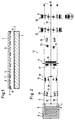
- the electrostatically chargeable adhesive plate in the exemplary embodiment shown has a base plate 1 to which a cover plate 3 or cover layer is fastened on the upper side, for example by means of an adhesive layer 2.
- the base plate 1 consists of a carrier material of high strength, for example made of wood or solid solid plastic, so that it supports the electrically active cover plate 3, which can also be provided in the form of a surface layer, without torsion and breakage and also with suitable starting points, for example for fastening aids such as eyelets or for bores.
- the electrically active cover plate 3 has on its underside a meander 4 in the form of correspondingly running conductor tracks for generating an electrostatic field which effects the sheet holder.
- the meander 4 is designed as a three-wire system. For this purpose there are two live meandering tracks 5, 6 are provided, between which a third meandering track 7 is arranged as a central conductor. This divides the electrostatic field into two halves of the same symmetry.
- All three meandering tracks 5, 6, 7 are surrounded by a framing conductor 8 which is fully and rigidly grounded and connected to the respective ends of the grounded third meandering track 7.
- the framing conductor 8 While the respective ends of the two live meander tracks 5, 6 are connected to the two high-voltage conductors 9, 10 of a power supply device 11, the framing conductor 8 is connected to a solid protective conductor 12 together with the grounded meander track 7. As can be seen from FIG. 2, this is looped through from the framing conductor 8 and the central conductor 7 of the meander 4 via a high-voltage cascade 13 and a mains disconnector 14 to the mains connection 15 (protective contact plug).
- the mains isolating part 14 which is designed as a mains transformer with primary winding 16 and secondary winding 17, separates the power supply device 11 into a primary circuit (on the right in FIG. 2) and in a secondary circuit (on the left in FIG. 2).
- the secondary winding 17 of the mains transformer 14 is rigidly grounded at its center via the protective conductor 12, so that the alternating voltage of the mains isolating part 14 is fed exactly in half to the following high-voltage cascade 13.
- the high-voltage cascade 13 which has correspondingly connected diodes 18 and capacitors 19, is rigidly grounded exactly in its center and is designed to be electrically strictly earth-symmetrical, so that it supplies two voltages which are reverse-polarized to earth, completely earth-symmetrically.
- Two real protective resistors 20 are provided in the output of the high-voltage cascade 13. These are dimensioned such that in normal operating conditions the voltage drop across them is insignificant, but that in the event of accidental contact with the adhesive plate, the short-circuit currents and discharge current surges of the capacitors 19 of the high-voltage cascade 13 are limited to such an extent that their diodes 18 remain undamaged.
- the high-voltage cascade 13 has an earth-symmetrically identical voltage limitation, which limits the two voltages of opposite polarity to earth supplied by the cascade 13.
- voltage limiting means in the illustrated embodiment in the form of varistors 21, are provided which limit the high DC voltage of opposite polarity to earth to a set level.
- the current limitation effected by means of the protective resistors 20 and the voltage limitation effected by means of the varistors 21 are designed symmetrically, so that each earth-symmetrical half of the secondary circuit of the power supply device 11 is protected independently and safely.
- the secondary high voltage prevailing in the secondary circuit is already roughly preset in the primary circuit of the power supply device 11, ie in front of the mains transformer 14. This is done by means of appropriate series resistors 22, which are designed either as real resistors and / or as reactive resistors. In this case, transmission losses through the system are minimized even when real series resistors 22 are used, because these series resistors 22 are arranged in front of the mains transformer 14. However, if these series resistors 22 are in the form of reactors or represent a combination of real and reactances, the secondary is roughly preset High voltage by means of the phase shift between current and voltage in AC mains. This setting is done almost lossless electrically.
- One or more capacitors 23 are arranged in front of the primary winding 16 of the mains transformer 14 for the purpose of reactive current compensation. As a result, the primary circuit is almost completely reduced in its current consumption or current flow to the pure active current consumption or active current flow. In connection with this, the inrush current of the mains transformer 14 is also significantly damped. This is done by means of one or more NTC resistors 24 (resistor with negative temperature coefficient or thermistor). As a result, the inrush current of the mains transformer 14 is damped to normal operating current. This means that the primary power supply fuses can be rated for the normal operational active current.
- a corresponding adjusting device or adjusting circuit 25 which has a resistance regulator with a reminder lamp.
- the resistance controller which is matched to the overall system, is made up of real and / or reactance resistors.
- the reminder lamp serves as a reminder that the adhesive force is in operation by the resistance regulator and that the adhesive force is reduced.
- the reminder lamp which is purely current-driven by a current transformer, is somewhat constant in its luminosity over the entire adjustment range, because the adjustment of the adhesive force caused by the resistance controller uses the phase shift in the AC alternating current to save losses. With this power adjustment, the system current remains relatively constant in relation to the very strongly changed adhesive force adjustment ratio.
- the entire system works on the basis of the network frequency purely analog and therefore does not generate a high frequency.
- the holding force adjustment effected by means of the adjusting circuit 25 and the presetting of the secondary high voltage effected by means of the series resistors 22 including the reactive current compensation achieved by means of the capacitors 23 and the attenuation of the inrush current achieved by means of the NTC resistors 24 work according to the analog principle.
Landscapes
- Emergency Protection Circuit Devices (AREA)
- Photoreceptors In Electrophotography (AREA)
- Polishing Bodies And Polishing Tools (AREA)
- Adhesives Or Adhesive Processes (AREA)
- Elimination Of Static Electricity (AREA)
- Rectifiers (AREA)
- Holding Or Fastening Of Disk On Rotational Shaft (AREA)
Claims (12)
- Plaquette adhésive susceptible d'être chargée de façon électrostatique pour maintenir en particulier des feuilles, des films, ou similaires en papier ou en matière plastique, comprenant une plaque de base (1), une plaque de couverture fixée sur cette dernière, ladite plaque de couverture présentant à la face inférieure un serpentin (4) sous la forme de pistes conductrices de tracé correspondant, afin de produire un champ électrostatique qui effectue le maintien des feuilles, et comprenant un dispositif d'alimentation en courant (11) auquel sont raccordées les pistes conductrices de la plaque de couverture (3), le serpentin (4) de la plaque de couverture (3) étant réalisé sous la forme d'un système à trois conducteurs avec deux pistes en serpentin (5, 6) qui conduisent le courant et une piste en serpentin (7) agencée entre elles en tant que conducteur médian, qui divise le champ électrostatique en deux moitiés symétriques par rapport à la terre,
caractérisée en ce que, pour empêcher un rayonnement latéral du champ électrostatique, le serpentin (4) est entouré par un conducteur d'entourage (8) mis à la terre, qui est relié au conducteur médian (7), et en ce qu'il est prévu un conducteur de protection massif (12) mis en boucle par le conducteur d'entourage (8) ainsi que par le conducteur médian (7) du serpentin (4) via une cascade (13) à haute tension et une partie d'isolement (14) vis-à-vis du réseau, jusqu'au raccordement au réseau (15). - Plaquette adhésive selon la revendication 1, caractérisée en ce que l'enroulement secondaire (17) de la partie d'isolement (14), réalisée sous la forme d'un transformateur de réseau, est relié de façon fixe à la terre en son milieu, de sorte que la tension alternative de la partie d'isolement (14) est alimentée en étant exactement réduite de moitié à la cascade (13) à haute tension qui suit.
- Plaquette adhésive selon l'une ou l'autre des revendications 1 et 2, caractérisée en ce que la cascade à haute tension (13) est réalisée avec ses diodes (18) et ses condensateurs (19), en vue d'augmenter et de redresser la tension, de manière symétrique par rapport à la terre et sur le plan électrique de sorte qu'elle produit une tension continue symétrique et de polarité opposée par rapport à la terre.
- Plaquette adhésive selon l'une des revendications 1 à 3, caractérisée en ce que la cascade à haute tension (13) comporte, en vue de limiter la tension à des valeurs égales symétriques, des moyens de limitation de tension, tels que des varistors (21) ou similaires, qui sont branchés entre le conducteur de protection médian (12) et les deux conducteurs à haute tension (9, 10), et qui limitent par rapport à la terre les deux tensions de polarité opposée fournies par la cascade à haute tension (13).
- Plaquette adhésive selon l'une des revendications 1 à 4, caractérisée en ce qu'elle est subdivisée, conjointement avec ses lignes d'alimentation (9, 10, 11) par deux résistances de protection (20) afin de limiter le courant de la cascade à haute tension (13) formant source, de telle sorte qu'en cas de contact inopiné l'énergie des condensateurs (19) de la cascade (13) se décharge uniquement de façon amortie.
- Plaquette adhésive selon l'une des revendications 1 à 5, caractérisée en ce qu'il est prévu dans le circuit primaire de la partie d'isolement (14) une ou plusieurs résistances préalables (22) pour effectuer un réglage préliminaire grossier de la haute tension secondaire.
- Plaquette adhésive selon l'une des revendications 1 à 6, caractérisée en ce qui est prévu dans le circuit primaire de la partie d'isolement (14) un ou plusieurs condensateurs (23) afin de compenser parfaitement la composante de courant réactif de sorte que grâce à cette compensation du courant réactif on élimine tous les courants d'aimantation inductifs du transformateur de réseau (14).
- Plaquette adhésive selon l'une des revendications 1 à 7, caractérisée en ce qui est prévu dans le circuit primaire de la partie d'isolement (14) une ou plusieurs résistances (24) à coefficient de température négatif, qui amortissent l'impulsion de courant à la fermeture du transformateur de réseau (14) à des intensités de courant normales en service.
- Plaquette adhésive selon l'une des revendications 1 à 8, caractérisée en ce que pour régler la force d'adhésion de la plaquette adhésive on prévoit dans le circuit primaire de la partie d'isolement (14) un plateau de résistances (25) qui est réalisé sous la forme d'une résistance réelle et/ou d'une réactance réglable.
- Plaquette adhésive selon la revendication 9, caractérisée en ce qu'il est prévu dans le circuit du plateau de résistances (25) une lampe-témoin sous la forme d'une lampe fluorescente.
- Plaquette adhésive selon l'une des revendications 1 à 10, caractérisée en ce que, pour éviter un rayonnement parasite à haute fréquence sur la base de la fréquence du courant alternatif du réseau, le dispositif d'alimentation en courant (11) est réalisé de manière à fonctionner de manière strictement analogique.
- Plaquette adhésive selon l'une des revendications 1 à 11, caractérisée en ce que la plaque de base (1) est réalisée en un matériau d'une solidité considérable, en particulier en bois ou en matière plastique massive solide, de telle manière qu'elle porte la plaque de couverture (3) ou la couche de couverture active sur le plan électrique, de manière à la protéger contre les torsions et les ruptures.
Applications Claiming Priority (2)
| Application Number | Priority Date | Filing Date | Title |
|---|---|---|---|
| DE4017786A DE4017786C1 (fr) | 1990-06-01 | 1990-06-01 | |
| DE4017786 | 1990-06-01 |
Publications (2)
| Publication Number | Publication Date |
|---|---|
| EP0480124A1 EP0480124A1 (fr) | 1992-04-15 |
| EP0480124B1 true EP0480124B1 (fr) | 1995-09-06 |
Family
ID=6407688
Family Applications (1)
| Application Number | Title | Priority Date | Filing Date |
|---|---|---|---|
| EP91108848A Expired - Lifetime EP0480124B1 (fr) | 1990-06-01 | 1991-05-29 | Plaque de maintien rechargeable électrostatiquement |
Country Status (8)
| Country | Link |
|---|---|
| EP (1) | EP0480124B1 (fr) |
| AT (1) | ATE127400T1 (fr) |
| AU (1) | AU7859591A (fr) |
| DE (2) | DE4017786C1 (fr) |
| IE (1) | IE911829A1 (fr) |
| PT (1) | PT97831A (fr) |
| WO (1) | WO1991018751A1 (fr) |
| ZA (1) | ZA914074B (fr) |
Families Citing this family (3)
| Publication number | Priority date | Publication date | Assignee | Title |
|---|---|---|---|---|
| DE4410091C2 (de) * | 1994-03-24 | 2003-01-09 | Helmut Woll | Verfahren zum Herstellen von elektrostatischen Hafttafeln |
| US7465684B2 (en) * | 2005-01-06 | 2008-12-16 | Buckeye Technologies Inc. | High strength and high elongation wipe |
| CN112933449B (zh) * | 2021-01-13 | 2022-01-21 | 安徽大学 | 一种生物压电式智能口罩及其智能控制方法 |
Family Cites Families (5)
| Publication number | Priority date | Publication date | Assignee | Title |
|---|---|---|---|---|
| DE1203969B (de) * | 1963-08-16 | 1965-10-28 | F L Moseley Company | Einrichtung zur Halterung eines blattfoermigen Materials durch elektrostatische Anziehungskraefte |
| DE3133367A1 (de) * | 1981-08-24 | 1985-04-25 | SKP Technik AG, Brugg | Vorrichtung zur halterung blattfoermiger gegenstaende, insbesondere zeichenbrett oder registrierplatte |
| DE8419399U1 (de) * | 1984-06-28 | 1985-07-25 | Wikete, Arno, 7542 Schömberg | Schreib- und Zeichenplatte mit elektrostatischer Papier- und Folienbefestigung |
| AT384780B (de) * | 1985-08-09 | 1988-01-11 | Goerz Electro Gmbh | Elektrostatische papierhalterung |
| FR2623445A1 (fr) * | 1987-11-19 | 1989-05-26 | Vinci Rene | Sous-main portable electronique |
-
1990
- 1990-06-01 DE DE4017786A patent/DE4017786C1/de not_active Expired - Fee Related
-
1991
- 1991-05-18 WO PCT/DE1991/000421 patent/WO1991018751A1/fr not_active Ceased
- 1991-05-18 AU AU78595/91A patent/AU7859591A/en not_active Abandoned
- 1991-05-29 IE IE182991A patent/IE911829A1/en unknown
- 1991-05-29 DE DE59106419T patent/DE59106419D1/de not_active Expired - Fee Related
- 1991-05-29 AT AT91108848T patent/ATE127400T1/de not_active IP Right Cessation
- 1991-05-29 ZA ZA914074A patent/ZA914074B/xx unknown
- 1991-05-29 EP EP91108848A patent/EP0480124B1/fr not_active Expired - Lifetime
- 1991-05-31 PT PT97831A patent/PT97831A/pt not_active Application Discontinuation
Also Published As
| Publication number | Publication date |
|---|---|
| ATE127400T1 (de) | 1995-09-15 |
| DE59106419D1 (de) | 1995-10-12 |
| PT97831A (pt) | 1993-06-30 |
| IE911829A1 (en) | 1991-12-04 |
| AU7859591A (en) | 1991-12-31 |
| EP0480124A1 (fr) | 1992-04-15 |
| WO1991018751A1 (fr) | 1991-12-12 |
| ZA914074B (en) | 1992-02-26 |
| DE4017786C1 (fr) | 1991-10-02 |
Similar Documents
| Publication | Publication Date | Title |
|---|---|---|
| EP0116275B1 (fr) | Compensateur de puissance réactive | |
| DE2524367A1 (de) | Schaltung zur umwandlung von wechselspannungen in eine gleichspannung konstanter groesse | |
| DE3338301C2 (fr) | ||
| EP0480124B1 (fr) | Plaque de maintien rechargeable électrostatiquement | |
| DE2729913B2 (de) | Entmagnetisierungsschaltungsanordnung in einem Farbfernsehempfänger und Farbfernsehempfänger mit einer solchen Anordnung | |
| DE2554825C3 (de) | Schaltungsanordnung zur Erzeugung einer Ausgangsspannung aus einer von einer Gleichspannungsquelle gelieferten Eingangsgleichspannung abhängig von einer vorgegebenen Sollspannung | |
| DE3308411C2 (de) | Spannungsversorgung für einen Elektroabscheider | |
| DE9006245U1 (de) | Elektrostatisch aufladbare Haftplatte | |
| DE3149447A1 (de) | Regelungsschaltung zum konstanthalten der betriebsspannung eines elektrischen verbrauchers | |
| EP0164774A1 (fr) | Dispositif de circuit pour régler la tension de l'arc dans des lampes à décharge à haute pression | |
| EP0120258B1 (fr) | Circuit économiseur d'énergie | |
| DE3418065C2 (fr) | ||
| EP0302433B1 (fr) | Convertisseur à récupération | |
| DE2742965A1 (de) | Vorrichtung zum unterbrechen eines gleichstromkreises | |
| EP2140735B1 (fr) | Ensemble circuit servant à amorcer et à faire fonctionner au moins une lampe à décharge | |
| DE2130324C3 (fr) | ||
| DE1187726B (de) | Anordnung zum Schutz einer mit Kathodenzerstaeubung arbeitenden ionischen Hochvakuumpumpen-Anordnung | |
| DE1171524B (de) | Wahlweise aus einer aufladbaren Batterie oder aus dem Wechselstromnetz zu betreibendes Elektronenblitzgeraet | |
| DE1936912C3 (de) | Schaltungsanordnung zur Abschaltung von Netzgeräten beim Anschalten an zu hohe Netzspannungen | |
| DE2708673C2 (de) | Schaltungsanordnung zur Einschalt-Strombegrenzung | |
| DE1025496B (de) | Strom- und Spannungsbegrenzung bei elektrostatischen Lackierungs- und Elektrofilteranlagen | |
| DE553192C (de) | Elektrische Schaltanordnung zur Speisung von Gleichstromkreisen, z. B. in Rundfunkgeraeten, aus einem Wechselstromnetz mittels Gleichrichters | |
| AT374310B (de) | Schaltungsanordnung fuer die versorgung von gleichstromverbrauchern aus einem wechselstromnetz | |
| DE3109087C2 (de) | Fernspeiseeinrichtung | |
| DE1557061C3 (de) | Einrichtung zum Regeln der Spannung eines Elektroabscheiders |
Legal Events
| Date | Code | Title | Description |
|---|---|---|---|
| PUAI | Public reference made under article 153(3) epc to a published international application that has entered the european phase |
Free format text: ORIGINAL CODE: 0009012 |
|
| AK | Designated contracting states |
Kind code of ref document: A1 Designated state(s): AT BE CH DE DK ES FR GB IT LI LU NL SE |
|
| 17P | Request for examination filed |
Effective date: 19921009 |
|
| 17Q | First examination report despatched |
Effective date: 19940426 |
|
| GRAA | (expected) grant |
Free format text: ORIGINAL CODE: 0009210 |
|
| AK | Designated contracting states |
Kind code of ref document: B1 Designated state(s): AT BE CH DE DK ES FR GB IT LI LU NL SE |
|
| PG25 | Lapsed in a contracting state [announced via postgrant information from national office to epo] |
Ref country code: IT Free format text: LAPSE BECAUSE OF FAILURE TO SUBMIT A TRANSLATION OF THE DESCRIPTION OR TO PAY THE FEE WITHIN THE PRE;WARNING: LAPSES OF ITALIAN PATENTS WITH EFFECTIVE DATE BEFORE 2007 MAY HAVE OCCURRED AT ANY TIME BEFORE 2007. THE CORRECT EFFECTIVE DATE MAY BE DIFFERENT FROM THE ONE RECORDED.SCRIBED TIME-LIMIT Effective date: 19950906 Ref country code: NL Free format text: LAPSE BECAUSE OF FAILURE TO SUBMIT A TRANSLATION OF THE DESCRIPTION OR TO PAY THE FEE WITHIN THE PRESCRIBED TIME-LIMIT Effective date: 19950906 Ref country code: FR Effective date: 19950906 Ref country code: BE Effective date: 19950906 Ref country code: DK Effective date: 19950906 Ref country code: GB Effective date: 19950906 Ref country code: ES Free format text: THE PATENT HAS BEEN ANNULLED BY A DECISION OF A NATIONAL AUTHORITY Effective date: 19950906 |
|
| REF | Corresponds to: |
Ref document number: 127400 Country of ref document: AT Date of ref document: 19950915 Kind code of ref document: T |
|
| REF | Corresponds to: |
Ref document number: 59106419 Country of ref document: DE Date of ref document: 19951012 |
|
| PG25 | Lapsed in a contracting state [announced via postgrant information from national office to epo] |
Ref country code: SE Effective date: 19951206 |
|
| NLV1 | Nl: lapsed or annulled due to failure to fulfill the requirements of art. 29p and 29m of the patents act | ||
| EN | Fr: translation not filed | ||
| GBV | Gb: ep patent (uk) treated as always having been void in accordance with gb section 77(7)/1977 [no translation filed] |
Effective date: 19950906 |
|
| PG25 | Lapsed in a contracting state [announced via postgrant information from national office to epo] |
Ref country code: AT Effective date: 19960529 |
|
| PG25 | Lapsed in a contracting state [announced via postgrant information from national office to epo] |
Ref country code: LU Free format text: LAPSE BECAUSE OF NON-PAYMENT OF DUE FEES Effective date: 19960531 Ref country code: LI Effective date: 19960531 Ref country code: CH Effective date: 19960531 |
|
| PLBE | No opposition filed within time limit |
Free format text: ORIGINAL CODE: 0009261 |
|
| STAA | Information on the status of an ep patent application or granted ep patent |
Free format text: STATUS: NO OPPOSITION FILED WITHIN TIME LIMIT |
|
| 26N | No opposition filed | ||
| PGFP | Annual fee paid to national office [announced via postgrant information from national office to epo] |
Ref country code: DE Payment date: 19961204 Year of fee payment: 6 |
|
| REG | Reference to a national code |
Ref country code: CH Ref legal event code: PL |
|
| PG25 | Lapsed in a contracting state [announced via postgrant information from national office to epo] |
Ref country code: DE Free format text: LAPSE BECAUSE OF NON-PAYMENT OF DUE FEES Effective date: 19980203 |