EP0480161A2 - Méthode pour calibrer un appareil de mesure - Google Patents
Méthode pour calibrer un appareil de mesure Download PDFInfo
- Publication number
- EP0480161A2 EP0480161A2 EP91114509A EP91114509A EP0480161A2 EP 0480161 A2 EP0480161 A2 EP 0480161A2 EP 91114509 A EP91114509 A EP 91114509A EP 91114509 A EP91114509 A EP 91114509A EP 0480161 A2 EP0480161 A2 EP 0480161A2
- Authority
- EP
- European Patent Office
- Prior art keywords
- lamellae
- measuring device
- test
- segments
- dielectric constant
- Prior art date
- Legal status (The legal status is an assumption and is not a legal conclusion. Google has not performed a legal analysis and makes no representation as to the accuracy of the status listed.)
- Granted
Links
Images


Classifications
-
- G—PHYSICS
- G01—MEASURING; TESTING
- G01R—MEASURING ELECTRIC VARIABLES; MEASURING MAGNETIC VARIABLES
- G01R35/00—Testing or calibrating of apparatus covered by the other groups of this subclass
- G01R35/005—Calibrating; Standards or reference devices, e.g. voltage or resistance standards, "golden" references
Definitions
- the invention is based on a method for calibrating a measuring device.
- a method for calibrating a measuring device uses a metallic outer sleeve, within which individual ring segments are arranged in parallel, each of which forms a capacitor with the outer part.
- the dielectric constant changes depending on the splitting of beam parts between the individual capacitor segments.
- a conclusion on the beam shape can be drawn from the change mentioned. This known method has proven to be capable of improvement.
- the method according to the invention with the characterizing features of the main claim has the advantage that the measuring accuracy of the fluid jet is improved and that above all the checking and calibration of the measuring device is possible in a simple manner.
- FIG. 1 shows a perspective view of the measuring device in FIG. 1, a calibration attachment in FIG. 2, likewise in a simplified and perspective representation, alternatively a calibration insert in FIGS. 3a to 3c, which permits the adjustment of an individual segment.
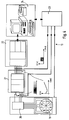
- Figure 4 shows the entire beam measuring device in a simplified representation.
- the entire measuring device is shown, the u. a. has a measuring disc 10, which consists of eight segments (0 to 7), each segment having four radially arranged lamellae, all designated 11, in such a way that they open a passage 12 in the middle thereof.
- the slats are vertical and - like the segments - have a regular division, i. H. their angular distances are exactly the same.
- the lamellae or segments 11 form capacitors whose capacitance C u when voltage is applied. a. depends essentially on the dielectric constant of the dielectric between the fins, e.g. B. air; they are made of copper.
- the measuring device is used in particular to measure jets emerging from an injection nozzle.
- the beam penetrates through the central opening 12. If it is not exactly concentric or diffuse or has side beams, these split-off parts penetrate between the lamellae, as a result of which the dielectric constant of the respective capacitor part changes.
- the capacity fluctuations are registered and recorded in the test and evaluation device 13. This gives an accurate picture of the nature of the beam. This can be visually observed or recorded on a screen.
- the device is particular designed to test throttle pin nozzles with a bevel for the intentional generation of a side jet.
- the mask in FIG. 2 consists of an annular outer body 15 with eight segments 16 made of plexiglass. Since the dielectric constant of the measuring device between the individual capacitors or segments is not always constant, mask 14 is used to calibrate the measuring device. It is inserted into the measuring disk in such a way that a lamella 17 rests on each lamella 11. The measuring device is then activated and the calibration is carried out. By introducing the plexiglass lamellae, the characteristic of this material causes a change in capacitance in the dielectric constant, which changes approximately in the same order of magnitude as is caused by a beam.
- the deviations are carried out in an evaluation device by a method as shown in FIG. 4.
- One capacitor is therefore calibrated for each insertion process. This is usually sufficient for checking the measuring device.
- the mask according to FIG. 2 can also be inserted twisted as often as it has lamellae (32 times).
- FIGS. 3a to 3c show an alternative to the mask according to FIG. 2 in different views.
- These calibration parts consist of individual segments 16 with test slats 17.
- all slats of a segment are checked (calibrated) at the same time.
- the successive insertion of such devices at different depths (3c) additionally allows the response behavior of the capacitors to be checked as a function of the insertion depth. This also applies to the mask according to FIG. 2.
- the measuring disk 10 is connected to an oscillator 20 which is operatively connected to an analog evaluation device 21 and a downstream capacitance measuring device 22. All three parts mentioned are also operatively connected to an electronic evaluation device 23, and this to a computer and display device 24. However, these parts have not been discussed further since it is not essential to the invention.
Landscapes
- Physics & Mathematics (AREA)
- General Physics & Mathematics (AREA)
- Measurement Of Resistance Or Impedance (AREA)
- Investigating Or Analyzing Materials By The Use Of Electric Means (AREA)
Applications Claiming Priority (2)
| Application Number | Priority Date | Filing Date | Title |
|---|---|---|---|
| DE4031754 | 1990-10-06 | ||
| DE4031754A DE4031754A1 (de) | 1990-10-06 | 1990-10-06 | Verfahren zum kalibrieren einer messeinrichtung |
Publications (3)
| Publication Number | Publication Date |
|---|---|
| EP0480161A2 true EP0480161A2 (fr) | 1992-04-15 |
| EP0480161A3 EP0480161A3 (fr) | 1994-02-23 |
| EP0480161B1 EP0480161B1 (fr) | 1995-11-02 |
Family
ID=6415778
Family Applications (1)
| Application Number | Title | Priority Date | Filing Date |
|---|---|---|---|
| EP91114509A Expired - Lifetime EP0480161B1 (fr) | 1990-10-06 | 1991-08-29 | Méthode pour calibrer un appareil de mesure |
Country Status (3)
| Country | Link |
|---|---|
| EP (1) | EP0480161B1 (fr) |
| JP (1) | JP3307662B2 (fr) |
| DE (2) | DE4031754A1 (fr) |
Family Cites Families (1)
| Publication number | Priority date | Publication date | Assignee | Title |
|---|---|---|---|---|
| DE3225554A1 (de) * | 1982-07-08 | 1984-01-12 | Robert Bosch Gmbh, 7000 Stuttgart | Messeinrichtung fuer fluidstrahlen |
-
1990
- 1990-10-06 DE DE4031754A patent/DE4031754A1/de not_active Withdrawn
-
1991
- 1991-08-29 DE DE59106819T patent/DE59106819D1/de not_active Expired - Fee Related
- 1991-08-29 EP EP91114509A patent/EP0480161B1/fr not_active Expired - Lifetime
- 1991-10-07 JP JP25882291A patent/JP3307662B2/ja not_active Expired - Fee Related
Also Published As
| Publication number | Publication date |
|---|---|
| DE59106819D1 (de) | 1995-12-07 |
| EP0480161A3 (fr) | 1994-02-23 |
| JPH04307361A (ja) | 1992-10-29 |
| JP3307662B2 (ja) | 2002-07-24 |
| EP0480161B1 (fr) | 1995-11-02 |
| DE4031754A1 (de) | 1992-04-09 |
Similar Documents
| Publication | Publication Date | Title |
|---|---|---|
| DE2942238A1 (de) | Verfahren und anordnung zum testen ionenselektiver elektroden | |
| DE3225554A1 (de) | Messeinrichtung fuer fluidstrahlen | |
| DE2212582A1 (de) | Vorrichtung zur UEberpruefung von Zuendanlagen | |
| DE3819101C2 (fr) | ||
| EP0480161B1 (fr) | Méthode pour calibrer un appareil de mesure | |
| DE2701777C2 (de) | Anordnung zur Erfassung der Spritzzeit und zum Ermitteln des von Einspritzdüsen erzeugten Strahlquerschnitts an Einspritzventilen | |
| DE2317793A1 (de) | Verfahren und vorrichtung zum orten einer quelle impulsartiger signale | |
| DE1977607U (de) | Messgefaess fuer eine einrichtung zum zaehlen von suspendierten teilchen. | |
| DE1802220B2 (de) | Verfahren und Vorrichtung zum Prüfen von Zigaretten | |
| CH622616A5 (fr) | ||
| DE2836925C3 (de) | Vorrichtung zur Kontrolle der Geometrie einer Ventilsitzringfase | |
| DE3441805C2 (fr) | ||
| DE102005045079A1 (de) | Konzept zum Testen eines Drucksensors und eine Düse | |
| DE2102005A1 (de) | Vorrichtung und Verfahren zur Harte messung | |
| DE102008040921A1 (de) | Referenzkörper zur Überprüfung von optischen oder taktilen Messsonden | |
| DE2918611C2 (de) | Gerät zur Messung einer ionisierenden Strahlung mit einer daran anschließbaren Meßsonde und Verfahren zur Einstellung eines Widerstandes der Meßsonde | |
| DE3135838A1 (de) | Verfahren zur fuellstandsmessung von mit pulvern oder fluessigkeiten gefuellten rohren oder huelsen | |
| DE2247032A1 (de) | Vorrichtung zur bestimmung wenigstens einer koordinate eines objektes, das entlang wenigstens einer koordinatenachse bewegbar ist | |
| DD287770A5 (de) | Kegelwinkelmessgeraet | |
| DE1773476A1 (de) | Verfahren und Einrichtung zum pneumatischen Messen | |
| DE3129998C2 (de) | "Verfahren und Vorrichtung zur zerstörungsfreien Messung des Ansprechdruckes von Umkehrberstscheiben" | |
| DE102023102206A1 (de) | Kontrastmessung zur Laserpulseinstellung | |
| DE3622902C2 (fr) | ||
| CH233888A (de) | Einrichtung zur oszillographischen Aufzeichnung, insbesondere einmaliger Vorgänge. | |
| DE2152654C3 (de) | Verfahren und Vorrichtung zur graphischen Ermittlung der Dehnungsgrenzen von Werkstoffproben |
Legal Events
| Date | Code | Title | Description |
|---|---|---|---|
| PUAI | Public reference made under article 153(3) epc to a published international application that has entered the european phase |
Free format text: ORIGINAL CODE: 0009012 |
|
| AK | Designated contracting states |
Kind code of ref document: A2 Designated state(s): DE FR GB IT |
|
| PUAL | Search report despatched |
Free format text: ORIGINAL CODE: 0009013 |
|
| AK | Designated contracting states |
Kind code of ref document: A3 Designated state(s): DE FR GB IT |
|
| 17P | Request for examination filed |
Effective date: 19940721 |
|
| 17Q | First examination report despatched |
Effective date: 19950309 |
|
| GRAA | (expected) grant |
Free format text: ORIGINAL CODE: 0009210 |
|
| AK | Designated contracting states |
Kind code of ref document: B1 Designated state(s): DE FR GB IT |
|
| ET | Fr: translation filed | ||
| REF | Corresponds to: |
Ref document number: 59106819 Country of ref document: DE Date of ref document: 19951207 |
|
| ITF | It: translation for a ep patent filed | ||
| GBT | Gb: translation of ep patent filed (gb section 77(6)(a)/1977) |
Effective date: 19960111 |
|
| PLBE | No opposition filed within time limit |
Free format text: ORIGINAL CODE: 0009261 |
|
| STAA | Information on the status of an ep patent application or granted ep patent |
Free format text: STATUS: NO OPPOSITION FILED WITHIN TIME LIMIT |
|
| 26N | No opposition filed | ||
| PGFP | Annual fee paid to national office [announced via postgrant information from national office to epo] |
Ref country code: FR Payment date: 20000822 Year of fee payment: 10 |
|
| PGFP | Annual fee paid to national office [announced via postgrant information from national office to epo] |
Ref country code: DE Payment date: 20001026 Year of fee payment: 10 |
|
| PGFP | Annual fee paid to national office [announced via postgrant information from national office to epo] |
Ref country code: GB Payment date: 20010814 Year of fee payment: 11 |
|
| REG | Reference to a national code |
Ref country code: GB Ref legal event code: IF02 |
|
| PG25 | Lapsed in a contracting state [announced via postgrant information from national office to epo] |
Ref country code: FR Free format text: LAPSE BECAUSE OF NON-PAYMENT OF DUE FEES Effective date: 20020430 |
|
| PG25 | Lapsed in a contracting state [announced via postgrant information from national office to epo] |
Ref country code: DE Free format text: LAPSE BECAUSE OF NON-PAYMENT OF DUE FEES Effective date: 20020501 |
|
| REG | Reference to a national code |
Ref country code: FR Ref legal event code: ST |
|
| PG25 | Lapsed in a contracting state [announced via postgrant information from national office to epo] |
Ref country code: GB Free format text: LAPSE BECAUSE OF NON-PAYMENT OF DUE FEES Effective date: 20020829 |
|
| GBPC | Gb: european patent ceased through non-payment of renewal fee |
Effective date: 20020829 |
|
| PG25 | Lapsed in a contracting state [announced via postgrant information from national office to epo] |
Ref country code: IT Free format text: LAPSE BECAUSE OF NON-PAYMENT OF DUE FEES;WARNING: LAPSES OF ITALIAN PATENTS WITH EFFECTIVE DATE BEFORE 2007 MAY HAVE OCCURRED AT ANY TIME BEFORE 2007. THE CORRECT EFFECTIVE DATE MAY BE DIFFERENT FROM THE ONE RECORDED. Effective date: 20050829 |