EP0480221A2 - Dispositif de commande avec au moins deux transmetteurs de signaux - Google Patents
Dispositif de commande avec au moins deux transmetteurs de signaux Download PDFInfo
- Publication number
- EP0480221A2 EP0480221A2 EP91116102A EP91116102A EP0480221A2 EP 0480221 A2 EP0480221 A2 EP 0480221A2 EP 91116102 A EP91116102 A EP 91116102A EP 91116102 A EP91116102 A EP 91116102A EP 0480221 A2 EP0480221 A2 EP 0480221A2
- Authority
- EP
- European Patent Office
- Prior art keywords
- signal
- housing
- button
- signal transmitters
- drive mechanism
- Prior art date
- Legal status (The legal status is an assumption and is not a legal conclusion. Google has not performed a legal analysis and makes no representation as to the accuracy of the status listed.)
- Granted
Links
Images

Classifications
-
- A—HUMAN NECESSITIES
- A47—FURNITURE; DOMESTIC ARTICLES OR APPLIANCES; COFFEE MILLS; SPICE MILLS; SUCTION CLEANERS IN GENERAL
- A47C—CHAIRS; SOFAS; BEDS
- A47C31/00—Details or accessories for chairs, beds, or the like, not provided for in other groups of this subclass, e.g. upholstery fasteners, mattress protectors, stretching devices for mattress nets
- A47C31/008—Use of remote controls
-
- A—HUMAN NECESSITIES
- A47—FURNITURE; DOMESTIC ARTICLES OR APPLIANCES; COFFEE MILLS; SPICE MILLS; SUCTION CLEANERS IN GENERAL
- A47C—CHAIRS; SOFAS; BEDS
- A47C20/00—Head-, foot- or like rests for beds, sofas or the like
- A47C20/04—Head-, foot- or like rests for beds, sofas or the like with adjustable inclination
- A47C20/041—Head-, foot- or like rests for beds, sofas or the like with adjustable inclination by electric motors
-
- F—MECHANICAL ENGINEERING; LIGHTING; HEATING; WEAPONS; BLASTING
- F15—FLUID-PRESSURE ACTUATORS; HYDRAULICS OR PNEUMATICS IN GENERAL
- F15B—SYSTEMS ACTING BY MEANS OF FLUIDS IN GENERAL; FLUID-PRESSURE ACTUATORS, e.g. SERVOMOTORS; DETAILS OF FLUID-PRESSURE SYSTEMS, NOT OTHERWISE PROVIDED FOR
- F15B7/00—Systems in which the movement produced is definitely related to the output of a volumetric pump; Telemotors
- F15B7/008—Systems in which the movement produced is definitely related to the output of a volumetric pump; Telemotors with rotary output
-
- F—MECHANICAL ENGINEERING; LIGHTING; HEATING; WEAPONS; BLASTING
- F15—FLUID-PRESSURE ACTUATORS; HYDRAULICS OR PNEUMATICS IN GENERAL
- F15B—SYSTEMS ACTING BY MEANS OF FLUIDS IN GENERAL; FLUID-PRESSURE ACTUATORS, e.g. SERVOMOTORS; DETAILS OF FLUID-PRESSURE SYSTEMS, NOT OTHERWISE PROVIDED FOR
- F15B7/00—Systems in which the movement produced is definitely related to the output of a volumetric pump; Telemotors
- F15B7/06—Details
- F15B7/08—Input units; Master units
-
- G—PHYSICS
- G05—CONTROLLING; REGULATING
- G05G—CONTROL DEVICES OR SYSTEMS INSOFAR AS CHARACTERISED BY MECHANICAL FEATURES ONLY
- G05G5/00—Means for preventing, limiting or returning the movements of parts of a control mechanism, e.g. locking controlling member
- G05G5/005—Means for preventing, limiting or returning the movements of parts of a control mechanism, e.g. locking controlling member for preventing unintentional use of a control mechanism
-
- H—ELECTRICITY
- H01—ELECTRIC ELEMENTS
- H01H—ELECTRIC SWITCHES; RELAYS; SELECTORS; EMERGENCY PROTECTIVE DEVICES
- H01H3/00—Mechanisms for operating contacts
- H01H3/02—Operating parts, i.e. for operating driving mechanism by a mechanical force external to the switch
- H01H3/20—Operating parts, i.e. for operating driving mechanism by a mechanical force external to the switch wherein an auxiliary movement thereof, or of an attachment thereto, is necessary before the main movement is possible or effective, e.g. for unlatching, for coupling
-
- H—ELECTRICITY
- H01—ELECTRIC ELEMENTS
- H01H—ELECTRIC SWITCHES; RELAYS; SELECTORS; EMERGENCY PROTECTIVE DEVICES
- H01H9/00—Details of switching devices, not covered by groups H01H1/00 - H01H7/00
- H01H9/02—Bases, casings, or covers
- H01H9/0214—Hand-held casings
Definitions
- the present invention relates to a control device with at least two signal generators, each having a drive mechanism.
- a disadvantage here is the lack of clarity about the locking already carried out and the separate setting of the locking as well as the high costs for such systems.
- the invention seeks to remedy this.
- the invention has for its object to improve a control device of the type mentioned so that the locking can be carried out on the control box of the bed itself.
- the drive mechanism has a button and that the locking element can be brought into and out of engagement with the button. This safely prevents the patient from activating the bed motor and at the same time enables the locking to be checked easily.
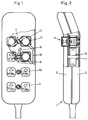
- Figures 1 and 2 show a control device for hospital beds with a housing 1, consisting of lower housing part 2 and upper housing part 3, which are connected to each other by screws, not shown, with a number of pneumatic pushbuttons 4, which are each arranged in pairs next to one another and functionally assigned and with a number of locking arrangements 5 according to the invention, which are arranged pivotably between two assigned pushbuttons 4.
- bearing sections 6 are provided in the upper and lower parts 2, 3 of the housing 1.
- the locking arrangement 5 consists of an organ with an axis 7, which are mounted in the bearing sections 6, and two tabs 8, 9, which protrude diametrically from the axis 7 and are formed integrally therewith.
- the bearing bore in the upper part 2 is open to the outside and the end face of the axis 7 is arranged flush with the surface of the upper part 2.
- this end face engaging means 10 are provided, in which an actuator (Not shown) can be used to pivot the locking member 5. Since the engagement means are visible from the outside, it can be read according to the invention whether the assigned pushbuttons 4 are locked.
- FIG. 3 shows the embodiment of the pneumatic push-button switch according to the invention, which is shown in the control device according to FIGS. 1 and 2.
- the pushbutton switch 1 contains a one-way working piston 11 with reset function and a pushbutton 12.
- the working piston 11 has a cylindrical housing 13 open on one side with a connecting piece 14 for a hose 15 (FIG. 1) and with recesses on the open side in order to close the pushbutton vent, a piston 16 with an annular portion 17 which abuts the inside of the housing 13, and a compression spring 18 which is arranged between the bottom 19 of the housing 13 and the piston 16 to reset the piston 16.
- the button 12 is a cap with a square basic shape. At the open end 4, the push button 12 has a flange 21 with which the push button 12 rests on the housing. Furthermore, a plunger 22, against which the piston 16 rests, is formed inside the cap.
- the working piston 11 is pivotally arranged in an annular extension 23 which is formed in one piece with the lower housing part 3.
- a hole 24 is formed in the bottom of the lower housing part 3, which is formed centrally to the shoulder 23, on the underside of the housing 13 of the working cylinder 11 a shoulder 25 is arranged, and a flange 26 is provided in the hole 24 is inserted and encompasses the approach 25.
- the locking member 5 has two tabs 8, 9, which rest against the housing 13 of the working cylinder 11 below the flange 21 of the pushbutton 12 when the locking member 5 is pivoted. These rags 8,9 serve in this position as a stop for the pushbutton 12, whereby the push-in movement of the pushbutton is blocked and the signal output is prevented.
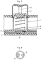
- FIG. 4 shows a second embodiment of a locking arrangement according to the invention, in which the locking is carried out on the rear of the housing 1.
- the housing 13 of the working piston 11 is pivotally arranged in the annular extension 23 in the lower housing part 3.
- a cutout 28 is therefore provided in the projection 23.
- the housing 13 of the working piston 11 when the button 12 is locked. Since the button 12 has a square shape, it is guided in a stable position in the upper housing part 2, i.e. the bearing of the cutouts, not shown, in the flange 21 is not changed when the button 12 is pressed in with respect to the housing 13 of the working piston 11. As a result, the flange 21 will rest on the shoulders 29 when the pushbutton 12 is pressed in and the push-in movement is blocked, so that the signal output is prevented. If the housing 13 or the working piston 11 is pivoted in the direction of arrow A and thus the lugs 29, they assume a position such that they are aligned with the recesses in the flange, not shown.
- engagement means are provided in the end face of the extension 25, which are designed analogously to the engagement means 10 shown in FIG.
- a valve is provided in the second embodiment in order to prevent the signal output.
- a channel 31 is provided instead of the connecting piece 14 and the hose.
- This channel 31 leads on the one hand into a plug arrangement (not shown) on a narrow side of the housing and on the other hand into the valve opening and communicates via an annular recess 32 with the working chamber of the working piston 11 and also via a second channel 33 with a vent hole 34 which is outside the working piston 11 opens into the housing 1.
- valve body 35 is disc-shaped and has in one side a recess 36 and a sealing ring 37 which are diametrically opposed to one another.
- engagement means (not shown) are provided, which can be designed analogously to the engagement means 10 of the first embodiment.
- the valve body 35 is rotatably mounted in the bottom of the lower housing part 3 and can be operated from the outside. 6 shows the valve body in such a way that the channel 31 is connected to the vent opening 34 via the recess 36 and the channel 33, so that when the pushbutton 12 is pressed in, the signal medium (air) is expelled via the vent opening 34, as a result of which the signal is emitted is prevented via the channel 31.
- valve body 35 If the valve body 35 is rotated, the connection between the channels 31 and 33 is interrupted while being sealed by the sealing ring 37.
- the pushbutton 12 When the pushbutton 12 is pressed in, the signal medium is passed on via the channel 31 and a signal is emitted.
- the embodiments of the signal transmitters described above are pneumatic pushbuttons with air as the signal medium.
- this can be done in the same way in order to prevent the signal output in the case of electrical pushbutton switches.
Landscapes
- Engineering & Computer Science (AREA)
- Physics & Mathematics (AREA)
- Fluid Mechanics (AREA)
- General Engineering & Computer Science (AREA)
- Mechanical Engineering (AREA)
- General Physics & Mathematics (AREA)
- Nursing (AREA)
- General Health & Medical Sciences (AREA)
- Health & Medical Sciences (AREA)
- Automation & Control Theory (AREA)
- Burglar Alarm Systems (AREA)
- Invalid Beds And Related Equipment (AREA)
- Component Parts Of Construction Machinery (AREA)
- Lock And Its Accessories (AREA)
- Apparatus For Radiation Diagnosis (AREA)
- Measuring Pulse, Heart Rate, Blood Pressure Or Blood Flow (AREA)
- Actuator (AREA)
- Selective Calling Equipment (AREA)
- Air Bags (AREA)
Applications Claiming Priority (2)
| Application Number | Priority Date | Filing Date | Title |
|---|---|---|---|
| CH3242/90A CH681833A5 (fr) | 1990-10-09 | 1990-10-09 | |
| CH3242/90 | 1990-10-09 |
Publications (3)
| Publication Number | Publication Date |
|---|---|
| EP0480221A2 true EP0480221A2 (fr) | 1992-04-15 |
| EP0480221A3 EP0480221A3 (en) | 1992-07-01 |
| EP0480221B1 EP0480221B1 (fr) | 1995-05-17 |
Family
ID=4251724
Family Applications (1)
| Application Number | Title | Priority Date | Filing Date |
|---|---|---|---|
| EP91116102A Expired - Lifetime EP0480221B1 (fr) | 1990-10-09 | 1991-09-21 | Dispositif de commande avec au moins deux transmetteurs de signaux |
Country Status (4)
| Country | Link |
|---|---|
| EP (1) | EP0480221B1 (fr) |
| AT (1) | ATE122806T1 (fr) |
| CH (1) | CH681833A5 (fr) |
| DE (1) | DE59105508D1 (fr) |
Cited By (3)
| Publication number | Priority date | Publication date | Assignee | Title |
|---|---|---|---|---|
| GB2349429A (en) * | 1999-04-20 | 2000-11-01 | Kipley Roydon Marks | Air switch operator |
| US9653227B2 (en) | 2011-10-13 | 2017-05-16 | Dewertokin Gmbh | Mechanically lockable hand switch |
| DE102006003891B4 (de) * | 2006-01-27 | 2018-05-30 | Leopold Kostal Gmbh & Co. Kg | Tastschalter und Verwendung des Tastschalters |
Families Citing this family (3)
| Publication number | Priority date | Publication date | Assignee | Title |
|---|---|---|---|---|
| SE521739C2 (sv) * | 1999-11-19 | 2003-12-02 | Bt Ind Ab | Förfarande för anpassining av reglage vid maskiner samt reglage för utövande av förfarandet |
| DK1671340T3 (da) * | 2003-10-10 | 2014-05-05 | Linak As | Elektrisk håndbetjening, især til elektrisk indstillelige hospitals- og plejesenge |
| ATE543192T1 (de) * | 2005-11-11 | 2012-02-15 | Linak As | Elektrische handsteuerung insbesondere für elektrisch einstellbare krankenhaus- und pflegebetten |
Family Cites Families (2)
| Publication number | Priority date | Publication date | Assignee | Title |
|---|---|---|---|---|
| US3080720A (en) * | 1960-06-23 | 1963-03-12 | Simmons Co | Remote control switch operating device |
| CA1263541A (fr) * | 1987-01-13 | 1989-12-05 | Bell-Northern Research Ltd. | Mecanisme a bouton-poussoir commande par outil pour controler le fonctionnement d'un systeme de verrouillage sur panneau |
-
1990
- 1990-10-09 CH CH3242/90A patent/CH681833A5/de not_active IP Right Cessation
-
1991
- 1991-09-21 AT AT91116102T patent/ATE122806T1/de not_active IP Right Cessation
- 1991-09-21 DE DE59105508T patent/DE59105508D1/de not_active Expired - Fee Related
- 1991-09-21 EP EP91116102A patent/EP0480221B1/fr not_active Expired - Lifetime
Cited By (5)
| Publication number | Priority date | Publication date | Assignee | Title |
|---|---|---|---|---|
| GB2349429A (en) * | 1999-04-20 | 2000-11-01 | Kipley Roydon Marks | Air switch operator |
| US6357233B1 (en) | 1999-04-20 | 2002-03-19 | Kipley Roydon Marks | Air switch operator |
| GB2349429B (en) * | 1999-04-20 | 2003-10-15 | Kipley Roydon Marks | Air switch operator |
| DE102006003891B4 (de) * | 2006-01-27 | 2018-05-30 | Leopold Kostal Gmbh & Co. Kg | Tastschalter und Verwendung des Tastschalters |
| US9653227B2 (en) | 2011-10-13 | 2017-05-16 | Dewertokin Gmbh | Mechanically lockable hand switch |
Also Published As
| Publication number | Publication date |
|---|---|
| ATE122806T1 (de) | 1995-06-15 |
| EP0480221A3 (en) | 1992-07-01 |
| EP0480221B1 (fr) | 1995-05-17 |
| DE59105508D1 (de) | 1995-06-22 |
| CH681833A5 (fr) | 1993-05-28 |
Similar Documents
| Publication | Publication Date | Title |
|---|---|---|
| EP1204846B1 (fr) | Actionneur rotatif | |
| EP0265883B1 (fr) | Commutateur rotatif | |
| EP0623942A1 (fr) | Codeur | |
| EP1690272B1 (fr) | Circuit et dispositif de detection de diverses positions d'un element de porte | |
| EP0172926B1 (fr) | Adaptateur de manoeuvre pour dispositifs de commande ou de signalisation, en particulier interrupteur d'arrêt d'urgence | |
| DE4443726A1 (de) | Mehrrichtungs-Eingabeschalter | |
| DE3041470C2 (fr) | ||
| EP0480221A2 (fr) | Dispositif de commande avec au moins deux transmetteurs de signaux | |
| DE102005001560A1 (de) | Drehsteller für elektrische oder elektronische Geräte in einem Kraftfahrzeug | |
| DE69614587T2 (de) | Verriegelungsmechanismus für mit einem Schlüssel betätigbarer Schalter | |
| EP0496105B1 (fr) | Armature sanitaire pour un fonctionnement à distance | |
| CH629882A5 (de) | Ventil zur steuerung fluidischer medien. | |
| DE19544467C1 (de) | Elektrische Signalgabeeinrichtung | |
| DE1150433B (de) | Fluessigkeitsdruckbetaetigter elektrischer Kleinschalter | |
| DE69808529T2 (de) | Pneumatisches Ventil, insbesondere für eine Kraftfahrzeugbremsvorrichtung | |
| DE2651376C2 (de) | Drucktastenanordnung zur Betätigung mindestens eines Schaltkontaktes eines elektrischen Schalters | |
| DE3532988C2 (de) | Elektrohydraulische Schaltvorrichtung | |
| EP0777246B1 (fr) | Interrupteur électrique | |
| CH679078A5 (fr) | ||
| EP0954000A2 (fr) | Interrupteur à pression | |
| DE3519368A1 (de) | Drehschalter | |
| EP0939416B1 (fr) | Interrupteur actionné par pression | |
| DE20305387U1 (de) | Not-Aus-Gerät mit integrierten Schaltelementen | |
| DE3877663T2 (de) | Indifferent arbeitender und ausloesepunkt-schalter. | |
| DE3805506C2 (de) | Mehrstellungsventil |
Legal Events
| Date | Code | Title | Description |
|---|---|---|---|
| PUAI | Public reference made under article 153(3) epc to a published international application that has entered the european phase |
Free format text: ORIGINAL CODE: 0009012 |
|
| AK | Designated contracting states |
Kind code of ref document: A2 Designated state(s): AT BE DE DK ES FR GB IT LU NL SE |
|
| PUAL | Search report despatched |
Free format text: ORIGINAL CODE: 0009013 |
|
| AK | Designated contracting states |
Kind code of ref document: A3 Designated state(s): AT BE DE DK ES FR GB IT LU NL SE |
|
| 17P | Request for examination filed |
Effective date: 19921219 |
|
| 17Q | First examination report despatched |
Effective date: 19940324 |
|
| GRAA | (expected) grant |
Free format text: ORIGINAL CODE: 0009210 |
|
| AK | Designated contracting states |
Kind code of ref document: B1 Designated state(s): AT BE DE DK ES FR GB IT LU NL SE |
|
| PG25 | Lapsed in a contracting state [announced via postgrant information from national office to epo] |
Ref country code: IT Free format text: LAPSE BECAUSE OF FAILURE TO SUBMIT A TRANSLATION OF THE DESCRIPTION OR TO PAY THE FEE WITHIN THE PRE;WARNING: LAPSES OF ITALIAN PATENTS WITH EFFECTIVE DATE BEFORE 2007 MAY HAVE OCCURRED AT ANY TIME BEFORE 2007. THE CORRECT EFFECTIVE DATE MAY BE DIFFERENT FROM THE ONE RECORDED.SCRIBED TIME-LIMIT Effective date: 19950517 Ref country code: BE Effective date: 19950517 Ref country code: NL Free format text: LAPSE BECAUSE OF NON-PAYMENT OF DUE FEES Effective date: 19950517 Ref country code: ES Free format text: THE PATENT HAS BEEN ANNULLED BY A DECISION OF A NATIONAL AUTHORITY Effective date: 19950517 Ref country code: DK Effective date: 19950517 Ref country code: GB Effective date: 19950517 |
|
| REF | Corresponds to: |
Ref document number: 122806 Country of ref document: AT Date of ref document: 19950615 Kind code of ref document: T |
|
| REF | Corresponds to: |
Ref document number: 59105508 Country of ref document: DE Date of ref document: 19950622 |
|
| PG25 | Lapsed in a contracting state [announced via postgrant information from national office to epo] |
Ref country code: SE Effective date: 19950817 |
|
| ET | Fr: translation filed | ||
| PG25 | Lapsed in a contracting state [announced via postgrant information from national office to epo] |
Ref country code: AT Effective date: 19950921 |
|
| PG25 | Lapsed in a contracting state [announced via postgrant information from national office to epo] |
Ref country code: LU Free format text: LAPSE BECAUSE OF NON-PAYMENT OF DUE FEES Effective date: 19950930 |
|
| NLV1 | Nl: lapsed or annulled due to failure to fulfill the requirements of art. 29p and 29m of the patents act | ||
| GBV | Gb: ep patent (uk) treated as always having been void in accordance with gb section 77(7)/1977 [no translation filed] |
Effective date: 19950517 |
|
| PLBE | No opposition filed within time limit |
Free format text: ORIGINAL CODE: 0009261 |
|
| STAA | Information on the status of an ep patent application or granted ep patent |
Free format text: STATUS: NO OPPOSITION FILED WITHIN TIME LIMIT |
|
| 26N | No opposition filed | ||
| PGFP | Annual fee paid to national office [announced via postgrant information from national office to epo] |
Ref country code: DE Payment date: 20010713 Year of fee payment: 11 |
|
| PGFP | Annual fee paid to national office [announced via postgrant information from national office to epo] |
Ref country code: FR Payment date: 20010727 Year of fee payment: 11 |
|
| PG25 | Lapsed in a contracting state [announced via postgrant information from national office to epo] |
Ref country code: DE Free format text: LAPSE BECAUSE OF NON-PAYMENT OF DUE FEES Effective date: 20030401 |
|
| PG25 | Lapsed in a contracting state [announced via postgrant information from national office to epo] |
Ref country code: FR Free format text: LAPSE BECAUSE OF NON-PAYMENT OF DUE FEES Effective date: 20030603 |
|
| REG | Reference to a national code |
Ref country code: FR Ref legal event code: ST |