EP0480221B1 - Steuervorrichtung mit mindestens zwei Signalgebern - Google Patents
Steuervorrichtung mit mindestens zwei Signalgebern Download PDFInfo
- Publication number
- EP0480221B1 EP0480221B1 EP91116102A EP91116102A EP0480221B1 EP 0480221 B1 EP0480221 B1 EP 0480221B1 EP 91116102 A EP91116102 A EP 91116102A EP 91116102 A EP91116102 A EP 91116102A EP 0480221 B1 EP0480221 B1 EP 0480221B1
- Authority
- EP
- European Patent Office
- Prior art keywords
- signal transmitters
- locking member
- control device
- order
- locking
- Prior art date
- Legal status (The legal status is an assumption and is not a legal conclusion. Google has not performed a legal analysis and makes no representation as to the accuracy of the status listed.)
- Expired - Lifetime
Links
- 230000007246 mechanism Effects 0.000 claims description 4
- 230000005540 biological transmission Effects 0.000 abstract 1
- 230000000903 blocking effect Effects 0.000 description 2
- 230000006835 compression Effects 0.000 description 1
- 238000007906 compression Methods 0.000 description 1
- 230000001419 dependent effect Effects 0.000 description 1
- 230000000474 nursing effect Effects 0.000 description 1
- 238000002560 therapeutic procedure Methods 0.000 description 1
Images
Classifications
-
- A—HUMAN NECESSITIES
- A47—FURNITURE; DOMESTIC ARTICLES OR APPLIANCES; COFFEE MILLS; SPICE MILLS; SUCTION CLEANERS IN GENERAL
- A47C—CHAIRS; SOFAS; BEDS
- A47C31/00—Details or accessories for chairs, beds, or the like, not provided for in other groups of this subclass, e.g. upholstery fasteners, mattress protectors, stretching devices for mattress nets
- A47C31/008—Use of remote controls
-
- A—HUMAN NECESSITIES
- A47—FURNITURE; DOMESTIC ARTICLES OR APPLIANCES; COFFEE MILLS; SPICE MILLS; SUCTION CLEANERS IN GENERAL
- A47C—CHAIRS; SOFAS; BEDS
- A47C20/00—Head-, foot- or like rests for beds, sofas or the like
- A47C20/04—Head-, foot- or like rests for beds, sofas or the like with adjustable inclination
- A47C20/041—Head-, foot- or like rests for beds, sofas or the like with adjustable inclination by electric motors
-
- F—MECHANICAL ENGINEERING; LIGHTING; HEATING; WEAPONS; BLASTING
- F15—FLUID-PRESSURE ACTUATORS; HYDRAULICS OR PNEUMATICS IN GENERAL
- F15B—SYSTEMS ACTING BY MEANS OF FLUIDS IN GENERAL; FLUID-PRESSURE ACTUATORS, e.g. SERVOMOTORS; DETAILS OF FLUID-PRESSURE SYSTEMS, NOT OTHERWISE PROVIDED FOR
- F15B7/00—Systems in which the movement produced is definitely related to the output of a volumetric pump; Telemotors
- F15B7/008—Systems in which the movement produced is definitely related to the output of a volumetric pump; Telemotors with rotary output
-
- F—MECHANICAL ENGINEERING; LIGHTING; HEATING; WEAPONS; BLASTING
- F15—FLUID-PRESSURE ACTUATORS; HYDRAULICS OR PNEUMATICS IN GENERAL
- F15B—SYSTEMS ACTING BY MEANS OF FLUIDS IN GENERAL; FLUID-PRESSURE ACTUATORS, e.g. SERVOMOTORS; DETAILS OF FLUID-PRESSURE SYSTEMS, NOT OTHERWISE PROVIDED FOR
- F15B7/00—Systems in which the movement produced is definitely related to the output of a volumetric pump; Telemotors
- F15B7/06—Details
- F15B7/08—Input units; Master units
-
- G—PHYSICS
- G05—CONTROLLING; REGULATING
- G05G—CONTROL DEVICES OR SYSTEMS INSOFAR AS CHARACTERISED BY MECHANICAL FEATURES ONLY
- G05G5/00—Means for preventing, limiting or returning the movements of parts of a control mechanism, e.g. locking controlling member
- G05G5/005—Means for preventing, limiting or returning the movements of parts of a control mechanism, e.g. locking controlling member for preventing unintentional use of a control mechanism
-
- H—ELECTRICITY
- H01—ELECTRIC ELEMENTS
- H01H—ELECTRIC SWITCHES; RELAYS; SELECTORS; EMERGENCY PROTECTIVE DEVICES
- H01H3/00—Mechanisms for operating contacts
- H01H3/02—Operating parts, i.e. for operating driving mechanism by a mechanical force external to the switch
- H01H3/20—Operating parts, i.e. for operating driving mechanism by a mechanical force external to the switch wherein an auxiliary movement thereof, or of an attachment thereto, is necessary before the main movement is possible or effective, e.g. for unlatching, for coupling
-
- H—ELECTRICITY
- H01—ELECTRIC ELEMENTS
- H01H—ELECTRIC SWITCHES; RELAYS; SELECTORS; EMERGENCY PROTECTIVE DEVICES
- H01H9/00—Details of switching devices, not covered by groups H01H1/00 - H01H7/00
- H01H9/02—Bases, casings, or covers
- H01H9/0214—Hand-held casings
Definitions
- the invention relates to a control device with at least two signal generators located next to one another, in particular for controlling hospital furniture, each of which has a drive mechanism with button buttons.
- Such a control device is known from US-A-3,080,720.
- This known control device serves as remote control of a control box. This enables the patient to carry out the various movements in his hospital bed himself. However, if an unauthorized movement of the hospital bed (not desired by the doctor or the nurses) should not take place, this blocking of the hospital bed movement would have to be carried out on the switch box itself, because no such blocking can be carried out on the control device itself.
- CA-A-1 263 541 discloses a switch which can be tilted into two positions, in which the tilting movement can be blocked by a rotatable eccentric cam, so that the switch is held in its off position. If you arranged two such switches next to each other, you would have two eccentric cams, which are located one behind the other and could be actuated by a single rotating axis.
- This axis lies transversely to the direction of movement of the switch or would lie transversely to the direction of movement of the two switches and must therefore lie below the switch or switches, as a result of which the thickness of the control device would be greatly increased, especially if the signal transmitters are pneumatic pushbuttons, in which then there must still be pistons and resilient return members (as in the subject of US-A-3 080 720).
- a disadvantage here is the lack of clarity about the locking already carried out and the separate setting of the locking outside the control device, as well as the high costs for such systems.
- the invention seeks to remedy this.
- the design of the control device according to the invention results from the characterizing part of patent claim 1. This allows the locking of the control device of the bed itself.
- X-ray units, therapy tables, nursing beds or hospital beds come into consideration as hospital furniture.
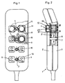
- Figures 1 and 2 show a control device for hospital beds with a housing 1, consisting of a lower housing part 3 and upper housing part 2, which are connected to each other by screws, not shown, with a number of pneumatic pushbuttons 4, which are arranged in pairs next to each other and functionally assigned and with a number of locking elements 5, which are arranged pivotably between two assigned pushbuttons 4.
- 1 bearing sections are in the upper and lower part 2, 3 of the housing 6 provided.
- the locking member 5 has an axis 7, which is mounted in a bearing section 6, and two tabs 8, 9, which protrude diametrically from the axis 7 and are formed integrally therewith.
- the bearing bore is open to the outside and the end face of the axis 7 is provided with an engagement means 10, into which a handling element (socket wrench), not shown, can be inserted by hand in order to rotate the locking element 5. Since the engagement means 10 are visible from the outside, it can be read whether the assigned pushbuttons 4 are locked or not.
- a handling element socketet wrench
- the pushbutton switch 4 contains a one-way working piston 16 with reset function and a pushbutton 12.
- the working piston 16 is seated in a cylinder 13 open on one side with a connecting piece 14 for a hose 15 (FIG. 1) and with lateral recesses in order to vent the pushbutton switch.
- the piston 16 lies sealingly against the inner wall of the cylinder 14.
- the button 12 is a cap with a square basic shape. At the open end, the pushbutton 12 has a flange 21. Furthermore, a plunger 22, against which the piston 16 rests, is formed inside the knob 12.
- the two tabs 8, 9 of the locking member 5 rest against the cylinder 13 below the flange 21 of the pushbutton 12. In this position, these tabs 8, 9 serve as a stop for the pushbutton 12, as a result of which the push-in movement of the pushbutton is blocked and the signal output is prevented. Since the button has a square shape, it is guided in a stable position in the upper housing part 2.
- the signal transmitters described above are pneumatic pushbuttons with air as the signal medium. In order to prevent the signal output from electrical pushbuttons, this can be done in the same way.
Landscapes
- Engineering & Computer Science (AREA)
- Physics & Mathematics (AREA)
- Fluid Mechanics (AREA)
- General Engineering & Computer Science (AREA)
- Mechanical Engineering (AREA)
- General Physics & Mathematics (AREA)
- Nursing (AREA)
- General Health & Medical Sciences (AREA)
- Health & Medical Sciences (AREA)
- Automation & Control Theory (AREA)
- Burglar Alarm Systems (AREA)
- Invalid Beds And Related Equipment (AREA)
- Component Parts Of Construction Machinery (AREA)
- Lock And Its Accessories (AREA)
- Apparatus For Radiation Diagnosis (AREA)
- Measuring Pulse, Heart Rate, Blood Pressure Or Blood Flow (AREA)
- Actuator (AREA)
- Selective Calling Equipment (AREA)
- Air Bags (AREA)
Description
- Die Erfindung betrifft eine Steuervorrichtung mit mindestens zwei nebeneinander liegenden Signalgebern, insbesondere zur Steuerung von Spitalmobiliar, die jeweils einen Antriebsmechanismus mit Tastenknöpfen aufweisen.
- Eine derartige Steuervorrichtung ist aus der US-A-3,080,720 bekannt. Diese bekannte Steuervorrichtung dient als Fernsteuerung eines Schaltkastens. Der Patient kann hierdurch selbst die verschiedenen Bewegungen bei seinem Spitalbett vornehmen. Sollte hierbei aber eine unbefugte (vom Arzt oder von den Krankenschwestern nicht gewünschte) Spitalbett-Bewegung unterbleiben, müsste diese Sperrung der Spitalbett-Bewegung am Schaltkasten selbst vorgenommen werden, denn an der Steuervorrichtung selbst kann keine derartige Sperrung vorgenommen werden.
- Durch die CA-A-1 263 541 ist ein in zwei Stellungen kippbarer Schalter bekannt, bei dem die Kippbewegung durch einen drehbaren Exzenternocken gesperrt werden kann, so dass der Schalter in seiner Aus-Stellung gehalten wird. Würde man zwei solche Schalter nebeneinander anordnen, hätte man zwei Exzenternocken, die hintereinander liegen und durch eine einzige drehbare Achse betätigt werden könnten. Diese Achse liegt quer zur Bewegungsrichtung des Schalters bzw. würde quer liegen zur Bewegungsrichtung der beiden Schalter und muss daher unterhalb des oder der Schalter liegen, wodurch die Dicke der Steuervorrichtung stark vergrössert werden würde, besonders dann, wenn die Signalgeber pneumatische Tastschalter sind, bei denen dann noch Kolben und federelastische Rückstellorgane vorhanden sein müssen (wie beim Gegenstand der US-A-3 080 720).
- Insbesondere bei der Steuerung von Bettenmotoren für Spitalbetten, bei der jeweils zwei Signalgeber für die Steuerung eines Motors benötigt werden, waren besondere Massnahmen erforderlich, um eine unbefugte Verstellung von Teilen des Bettes zu verhindern. Wegen den hohen Sicherheitsanforderungen mussten besondere Verriegelungsschaltungen in eigens dafür vorgesehenen Schaltkästen vorgesehen werden.
- Als nachteilig erweist sich dabei die Unübersichtlichkeit über die bereits vorgenommene Verriegelung und die gesonderte Einstellung der Verriegelung ausserhalb der Steuervorrichtung als auch die hohen Kosten für solche Anlagen.
- Hier will die Erfindung Abhilfe schaffen. Die erfindungsgemässe Ausbildung der Steuervorrichtung ergibt sich aus dem kennzeichnenden Teil des Patentanspruchs 1. Hierdurch kann die Verriegelung an der Steuervorrichtung des Bettes selbst vorgenommen werden.
- Als Spitalmobiliar kommen Röntgeneinheiten, Therapietische, Pflegebetten oder Spitalbetten infrage.
- Weitere Ausführungsformen der Erfindung ergeben sich aus den abhängigen Ansprüchen.
- Im folgenden wird die Erfindung anhand eines Ausführungsbeispiels in der beiliegenden Zeichnung erläutert.
- Es zeigen:
- Figur 1 eine teilweise aufgebrochen dargestellte Draufsicht auf die Steuervorrichtung, und
- Figur 2 eine teilweise aufgebrochen dargestellte Seitenansicht der Steuervorrichtung gemäss Figur 1.
- Die Figuren 1 und 2 zeigen eine Steuervorrichtung für Spitalbetten mit einem Gehäuse 1, bestehend aus einem Gehäuseunterteil 3 und Gehäuseoberteil 2, die durch nicht dargestellte Schrauben miteinander verbunden sind, mit einer Anzahl von pneumatischen Tastschaltern 4, die jeweils paarweise nebeneinanderliegend angeordnet und funktionsmässig zugeordnet sind und mit einer Anzahl von Verriegelungsorganen 5, die zwischen zwei zugeordneten Tastschaltern 4 schwenkbar angeordnet sind. Hierzu sind im Ober- und Unterteil 2, 3 des Gehäuses 1 Lagerabschnitte 6 vorgesehen. Das Verriegelungsorgan 5 hat eine Achse 7, die in einem Lagerabschnitt 6 gelagert ist, und zwei Lappen 8,9, die diametral von der Achse 7 abstehen und einstückig mit dieser ausgebildet sind. Ferner ist im Oberteil 2 die Lagerbohrung nach aussen offen und die Stirnfläche der Achse 7 ist mit einem Eingriffsmittel 10 versehen, in die ein nicht dargestelltes Handhabungsorgan (Steckschlüssel) von Hand einsetzbar ist, um das Verriegelungsorgan 5 zu drehen. Da die Eingriffsmittel 10 von aussen sichtbar sind, kann abgelesen werden, ob die zugeordneten Tastschalter 4 verriegelt sind oder nicht.
- Der Tastschalter 4 enthält einen Einweg-Arbeitskolben 16 mit Rückstellfunktion und einen Tastknopf 12. Der Arbeitskolben 16 sitzt in einem einseitig offenen Zylinder 13 mit einem Anschlussstutzen 14 für einen Schlauch 15 (Figur 1) und mit seitlichen Ausnehmungen, um den Tastschalter zu entlüften. Der Kolben 16 liegt abdichtend an der Innenwandung des Zylinders 14 an. Eine Druckfeder 18, die zwischen dem Boden des Zylinders 13 und dem Kolben 16 angeordnet ist dient dazu, den Kolben 16 und den Tastknopf 12 zurückzustellen.
- Der Tastknopf 12 ist eine Kappe mit viereckiger Grundform. Am offenen Ende hat der Tastknopf 12 einen Flansch 21. Ferner ist innerhalb des Knopfes 12 ein Stössel 22 angeformt, an dem der Kolben 16 anliegt.
- Die zwei Lappen 8,9 des Verriegelungsorganes 5 liegen in der Betriebsstellung des Verriegelungsorgans 5 unterhalb des Flansches 21 des Tastknopfes 12 am Zylinder 13 an. Diese Lappen 8,9 dienen in dieser Stellung als Anschlag für den Tastknopf 12, wodurch die Eindrückbewegung des Tastknopfes blockiert wird, und die Signalabgabe verhindert wird. Da der Tastenknopf eine viereckige Form hat, wird er lagestabil im Gehäuseoberteil 2 geführt.
- Die vorstehend beschriebenen Signalgeber sind pneumatische Tastschalter mit Luft als Signalmedium. Um die Signalabgabe bei elektrischen Tastschaltern zu verhindern, kann dies auf die gleiche Art und Weise erfolgen.
Claims (6)
- Steuervorrichtung mit mindestens zwei nebeneinander liegenden Signalgebern (4), insbesondere zur Steuerung von Spitalmobiliar, die jeweils einen Antriebsmechanismus (12,16,13,18) mit Tastenknöpfen (12) aufweisen, gekennzeichnet durch ein einziges Verriegelungsorgan (5) für zwei nebeneinander liegende Signalgeber (4), das mit diesen beiden Signalgebern (4) in Eingriff bringbar ist, um die Signalausgabe zu verhindern, wobei das Verriegelungsorgan (5) zwischen den beiden nebeneinanderliegenden Antriebsmechanismen (12,16,13,18) schwenkbar angeordnet ist, um die Tastenknöpfe (12) der beiden nebeneinander liegen Signalgeber (4) gleichzeitig zu blockieren.
- Vorrichtung nach Anspruch 1, dadurch gekennzeichnet, dass das Verriegelungsorgan (5) eine Schwenkachse (7) und zwei davon radial abstehende Lappen (8,9) aufweist, die in der Betriebsstellung des Verriegelungsorgans (5) in den Verschiebeweg der beiden Tastenknöpfe (12) der beiden nebeneinander liegenden Signalgeber (4) schwenkbar sind.
- Vorrichtung nach Anspruch 1 oder 2, dadurch gekennzeichnet, dass das Verriegelungsorgan (5) mit einem Eingriffsmittel (10) versehen ist, um das Verriegelungsorgan (5) in seine Betriebsstellung und aus seiner Betriebsstellung zu bringen.
- Vorrichtung nach Anspruch 1, dadurch gekennzeichnet, dass jeder Antriebsmechanismus neben dem Tastenknopf (12) noch einen Zylinder (13), einen darin geführten Kolben (16) und ein als Feder ausgebildetes Rückstellorgan (18) für den Kolben (16) und Tastenknopf (12) umfasst.
- Vorrichtung nach Anspruch 3, dadurch gekennzeichnet, dass das Eingriffsmittel (10) für je ein Verriegelungsorgan (5) auf der Vorderseite des Vorrichtungsgehäuses liegt, um die Verriegelung des Signalgebers (4) anzuzeigen.
- Vorrichtung nach einem der Ansprüche 1 bis 5, dadurch gekennzeichnet, dass die Signalgeber (4) pneumatische Tastschalter sind.
Applications Claiming Priority (2)
| Application Number | Priority Date | Filing Date | Title |
|---|---|---|---|
| CH3242/90A CH681833A5 (de) | 1990-10-09 | 1990-10-09 | |
| CH3242/90 | 1990-10-09 |
Publications (3)
| Publication Number | Publication Date |
|---|---|
| EP0480221A2 EP0480221A2 (de) | 1992-04-15 |
| EP0480221A3 EP0480221A3 (en) | 1992-07-01 |
| EP0480221B1 true EP0480221B1 (de) | 1995-05-17 |
Family
ID=4251724
Family Applications (1)
| Application Number | Title | Priority Date | Filing Date |
|---|---|---|---|
| EP91116102A Expired - Lifetime EP0480221B1 (de) | 1990-10-09 | 1991-09-21 | Steuervorrichtung mit mindestens zwei Signalgebern |
Country Status (4)
| Country | Link |
|---|---|
| EP (1) | EP0480221B1 (de) |
| AT (1) | ATE122806T1 (de) |
| CH (1) | CH681833A5 (de) |
| DE (1) | DE59105508D1 (de) |
Cited By (1)
| Publication number | Priority date | Publication date | Assignee | Title |
|---|---|---|---|---|
| WO2013053764A1 (de) | 2011-10-13 | 2013-04-18 | Dewertokin Gmbh | Mechanisch sperrbarer handschalter |
Families Citing this family (5)
| Publication number | Priority date | Publication date | Assignee | Title |
|---|---|---|---|---|
| US6357233B1 (en) | 1999-04-20 | 2002-03-19 | Kipley Roydon Marks | Air switch operator |
| SE521739C2 (sv) * | 1999-11-19 | 2003-12-02 | Bt Ind Ab | Förfarande för anpassining av reglage vid maskiner samt reglage för utövande av förfarandet |
| DK1671340T3 (da) * | 2003-10-10 | 2014-05-05 | Linak As | Elektrisk håndbetjening, især til elektrisk indstillelige hospitals- og plejesenge |
| ATE543192T1 (de) * | 2005-11-11 | 2012-02-15 | Linak As | Elektrische handsteuerung insbesondere für elektrisch einstellbare krankenhaus- und pflegebetten |
| DE102006003891B4 (de) * | 2006-01-27 | 2018-05-30 | Leopold Kostal Gmbh & Co. Kg | Tastschalter und Verwendung des Tastschalters |
Family Cites Families (2)
| Publication number | Priority date | Publication date | Assignee | Title |
|---|---|---|---|---|
| US3080720A (en) * | 1960-06-23 | 1963-03-12 | Simmons Co | Remote control switch operating device |
| CA1263541A (en) * | 1987-01-13 | 1989-12-05 | Bell-Northern Research Ltd. | Tool operated pushbutton mechanism for controlling the actuation of a panel-latching system |
-
1990
- 1990-10-09 CH CH3242/90A patent/CH681833A5/de not_active IP Right Cessation
-
1991
- 1991-09-21 AT AT91116102T patent/ATE122806T1/de not_active IP Right Cessation
- 1991-09-21 DE DE59105508T patent/DE59105508D1/de not_active Expired - Fee Related
- 1991-09-21 EP EP91116102A patent/EP0480221B1/de not_active Expired - Lifetime
Cited By (4)
| Publication number | Priority date | Publication date | Assignee | Title |
|---|---|---|---|---|
| WO2013053764A1 (de) | 2011-10-13 | 2013-04-18 | Dewertokin Gmbh | Mechanisch sperrbarer handschalter |
| DE102011084464A1 (de) | 2011-10-13 | 2013-04-18 | Dewert Antriebs- Und Systemtechnik Gmbh | Mechanisch sperrbarer Schalter |
| DE102011084464B4 (de) * | 2011-10-13 | 2013-09-05 | Dewert Antriebs- Und Systemtechnik Gmbh | Mechanisch sperrbare Kabelfernbedienung |
| CN104106119A (zh) * | 2011-10-13 | 2014-10-15 | 德韦尔托金有限责任公司 | 可机械锁定的手动开关 |
Also Published As
| Publication number | Publication date |
|---|---|
| ATE122806T1 (de) | 1995-06-15 |
| EP0480221A3 (en) | 1992-07-01 |
| EP0480221A2 (de) | 1992-04-15 |
| DE59105508D1 (de) | 1995-06-22 |
| CH681833A5 (de) | 1993-05-28 |
Similar Documents
| Publication | Publication Date | Title |
|---|---|---|
| DE69014330T2 (de) | Behälterkappe mit Anzeigevorrichtung. | |
| EP0123184B1 (de) | Tastaturanordnung | |
| EP1336691A1 (de) | Sanitäre Näherungsarmatur | |
| EP3511967B1 (de) | Set aus adaptermodulen | |
| EP0480221B1 (de) | Steuervorrichtung mit mindestens zwei Signalgebern | |
| EP0961958B1 (de) | Betätigungsvorrichtung für ein heizkörperventil | |
| DE202006021036U1 (de) | Elektrische Handbedienung, insbesondere für elektrisch ein- bzw. verstellbare Krankenhaus- und Pflegebetten | |
| DE2853880C2 (de) | Druckknopftaster | |
| EP0172926A1 (de) | Betätigungsvorsatz für elektrische Befehls- und Meldegeräte, insbesondere Not-Aus-Schalter | |
| DE102005001560A1 (de) | Drehsteller für elektrische oder elektronische Geräte in einem Kraftfahrzeug | |
| DE102005063321B4 (de) | Steuereinrichtung mit Handbedienung für Verstellantriebe | |
| EP0325194B1 (de) | Schaltbares Ueberdruckventil für strömende Medien | |
| DE19544467C1 (de) | Elektrische Signalgabeeinrichtung | |
| DE2534179A1 (de) | Schaltervorrichtung zur stellungsbegrenzung | |
| EP1451651A2 (de) | Elektromotorischer möbelantrieb | |
| DE3514312A1 (de) | Behaeltnis, insbesondere fuer medikamente | |
| EP4170210B1 (de) | Ventileinrichtung sowie fahrzeug mit einer ventileinrichtung | |
| DE29510495U1 (de) | Betätigungseinrichtung für Toiletten | |
| DE4107076C2 (de) | Kombinationsschloß mit veränderbarem Schlüsselgeheimnis für Behältnisse, wie Koffer, Aktentaschen od. dgl. | |
| DE102017105461A1 (de) | Manuell betätigbares Bedienelement | |
| WO1993007782A1 (de) | Stuhl, insbesondere bürostuhl | |
| DE8327028U1 (de) | Permutationsschloß | |
| DE4111150A1 (de) | Sicherheitsschalter | |
| DE29905043U1 (de) | Fernbedienungs-Vorrichtung | |
| DE1466117C3 (de) |
Legal Events
| Date | Code | Title | Description |
|---|---|---|---|
| PUAI | Public reference made under article 153(3) epc to a published international application that has entered the european phase |
Free format text: ORIGINAL CODE: 0009012 |
|
| AK | Designated contracting states |
Kind code of ref document: A2 Designated state(s): AT BE DE DK ES FR GB IT LU NL SE |
|
| PUAL | Search report despatched |
Free format text: ORIGINAL CODE: 0009013 |
|
| AK | Designated contracting states |
Kind code of ref document: A3 Designated state(s): AT BE DE DK ES FR GB IT LU NL SE |
|
| 17P | Request for examination filed |
Effective date: 19921219 |
|
| 17Q | First examination report despatched |
Effective date: 19940324 |
|
| GRAA | (expected) grant |
Free format text: ORIGINAL CODE: 0009210 |
|
| AK | Designated contracting states |
Kind code of ref document: B1 Designated state(s): AT BE DE DK ES FR GB IT LU NL SE |
|
| PG25 | Lapsed in a contracting state [announced via postgrant information from national office to epo] |
Ref country code: IT Free format text: LAPSE BECAUSE OF FAILURE TO SUBMIT A TRANSLATION OF THE DESCRIPTION OR TO PAY THE FEE WITHIN THE PRE;WARNING: LAPSES OF ITALIAN PATENTS WITH EFFECTIVE DATE BEFORE 2007 MAY HAVE OCCURRED AT ANY TIME BEFORE 2007. THE CORRECT EFFECTIVE DATE MAY BE DIFFERENT FROM THE ONE RECORDED.SCRIBED TIME-LIMIT Effective date: 19950517 Ref country code: BE Effective date: 19950517 Ref country code: NL Free format text: LAPSE BECAUSE OF NON-PAYMENT OF DUE FEES Effective date: 19950517 Ref country code: ES Free format text: THE PATENT HAS BEEN ANNULLED BY A DECISION OF A NATIONAL AUTHORITY Effective date: 19950517 Ref country code: DK Effective date: 19950517 Ref country code: GB Effective date: 19950517 |
|
| REF | Corresponds to: |
Ref document number: 122806 Country of ref document: AT Date of ref document: 19950615 Kind code of ref document: T |
|
| REF | Corresponds to: |
Ref document number: 59105508 Country of ref document: DE Date of ref document: 19950622 |
|
| PG25 | Lapsed in a contracting state [announced via postgrant information from national office to epo] |
Ref country code: SE Effective date: 19950817 |
|
| ET | Fr: translation filed | ||
| PG25 | Lapsed in a contracting state [announced via postgrant information from national office to epo] |
Ref country code: AT Effective date: 19950921 |
|
| PG25 | Lapsed in a contracting state [announced via postgrant information from national office to epo] |
Ref country code: LU Free format text: LAPSE BECAUSE OF NON-PAYMENT OF DUE FEES Effective date: 19950930 |
|
| NLV1 | Nl: lapsed or annulled due to failure to fulfill the requirements of art. 29p and 29m of the patents act | ||
| GBV | Gb: ep patent (uk) treated as always having been void in accordance with gb section 77(7)/1977 [no translation filed] |
Effective date: 19950517 |
|
| PLBE | No opposition filed within time limit |
Free format text: ORIGINAL CODE: 0009261 |
|
| STAA | Information on the status of an ep patent application or granted ep patent |
Free format text: STATUS: NO OPPOSITION FILED WITHIN TIME LIMIT |
|
| 26N | No opposition filed | ||
| PGFP | Annual fee paid to national office [announced via postgrant information from national office to epo] |
Ref country code: DE Payment date: 20010713 Year of fee payment: 11 |
|
| PGFP | Annual fee paid to national office [announced via postgrant information from national office to epo] |
Ref country code: FR Payment date: 20010727 Year of fee payment: 11 |
|
| PG25 | Lapsed in a contracting state [announced via postgrant information from national office to epo] |
Ref country code: DE Free format text: LAPSE BECAUSE OF NON-PAYMENT OF DUE FEES Effective date: 20030401 |
|
| PG25 | Lapsed in a contracting state [announced via postgrant information from national office to epo] |
Ref country code: FR Free format text: LAPSE BECAUSE OF NON-PAYMENT OF DUE FEES Effective date: 20030603 |
|
| REG | Reference to a national code |
Ref country code: FR Ref legal event code: ST |