EP0480351A1 - Formschliessvorrichtung - Google Patents
Formschliessvorrichtung Download PDFInfo
- Publication number
- EP0480351A1 EP0480351A1 EP91117044A EP91117044A EP0480351A1 EP 0480351 A1 EP0480351 A1 EP 0480351A1 EP 91117044 A EP91117044 A EP 91117044A EP 91117044 A EP91117044 A EP 91117044A EP 0480351 A1 EP0480351 A1 EP 0480351A1
- Authority
- EP
- European Patent Office
- Prior art keywords
- shutter
- piston
- base plate
- hollow section
- cylinder
- Prior art date
- Legal status (The legal status is an assumption and is not a legal conclusion. Google has not performed a legal analysis and makes no representation as to the accuracy of the status listed.)
- Granted
Links
Images

Classifications
-
- B—PERFORMING OPERATIONS; TRANSPORTING
- B29—WORKING OF PLASTICS; WORKING OF SUBSTANCES IN A PLASTIC STATE IN GENERAL
- B29C—SHAPING OR JOINING OF PLASTICS; SHAPING OF MATERIAL IN A PLASTIC STATE, NOT OTHERWISE PROVIDED FOR; AFTER-TREATMENT OF THE SHAPED PRODUCTS, e.g. REPAIRING
- B29C45/00—Injection moulding, i.e. forcing the required volume of moulding material through a nozzle into a closed mould; Apparatus therefor
- B29C45/17—Component parts, details or accessories; Auxiliary operations
- B29C45/64—Mould opening, closing or clamping devices
- B29C45/67—Mould opening, closing or clamping devices hydraulic
- B29C45/6707—Mould opening, closing or clamping devices hydraulic without relative movement between the piston and the cylinder of the clamping device during the mould opening or closing movement
- B29C45/6714—Mould opening, closing or clamping devices hydraulic without relative movement between the piston and the cylinder of the clamping device during the mould opening or closing movement using a separate element transmitting the mould clamping force from the clamping cylinder to the mould
Definitions
- This invention relates to a so-called shutter-type clamping device.
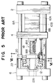
- Figs. 5 and 6 shows a conventional shutter-type clamping device for use in an injection molding machine or the like (USP No. 4,201,553).
- the device shown includes a stationary platen 2, a movable platen 4, a base plate 6, tie bars 8A through 8D, and molds 10A and 10B respectively attached to the stationary and movable platens 2 and 4.
- the reference numeral 14 indicates a cylinder firmly attached to the base plate 6, and, the reference numeral 16 indicates a flange provided at the opening of the cylinder 14.
- a protrusion 18 which is composed of a nut 18A and a screw bolt 18B.
- This protrusion 18 has the function of adjusting the mold thickness by varying the length of that section thereof in which the nut and the screw bolt are engaged with each other, and is formed as a cylinder whose size is such that it can enter the hollow section 12A of the piston 12 mentioned above.
- a shutter 20 by means of which the end opening of the hollow section 12A can be closed.
- This shutter 20 is arranged in such a manner as to be slidable along the tie bar 8A and as to be able to appropriately follow the axial movement of the piston 12 by means of a shutter gap adjustment mechanism 22.
- this shutter 20 consists of a swing arm 20B adapted to swing around the tie bar 8A, and a shutter body 20A attached to this swing arm, with the hollow section 12A of the piston 12 being opened and closed by a cylinder 28.
- the reference numeral 26 indicates a moving cylinder for opening and closing the movable platen 4.
- This conventional shutter-type clamping device closes the shutter 20 when performing clamping, transmitting the pressing force of the clamping piston 12 to the movable platen 4 through the protrusion 18.
- the shutter 20 is opened, whereby the protrusion 18 of the movable plate 4 is allowed to enter the hollow section 12A of the piston 12, so that the movable platen 4 can retreat.
- the shutter 20, or the cylinder 28 for driving the same is attached to the tie bar 8A or 8D, so that the shutter 20, the cylinder 28, which drives it, and the piston 12 make separate movements, resulting in an unstable shutter operation, which has a bad influence on the mounting quality of the members connecting the shutter 20 and the shutter driving cylinder 28 with each other.
- This invention has been made in view of the above-mentioned problems in the prior art. It is accordingly an object of this invention to provide a shutter-type clamping device which helps to improve the shutter opening/closing operation in terms of safety and attain a high level of operational efficiency in the assembly and replacement of the members related to the shutter, thereby making it possible to reduce parts cost and realize a quality clamping device.
- the present invention provides a shutter-type clamping device comprising a stationary platen; a movable platen; a base plate; a clamping piston which is lodged in a cylinder provided on the base plate and which has a hollow section; a protrusion provided on the movable platen and having configuration which allows it to enter the hollow section of the piston; and a shutter which allows or hinders the entry of the protrusion into the above-mentioned hollow section; the shutter being attached to the above-mentioned piston and arranged in such a manner as to be capable of moving forwards and backwards and incapable of rotating with respect to a member on the side of the base plate.
- the shutter is not attached to the tie bar, etc. but to the piston itself. Further, the shutter is arranged in such a manner as to be capable of moving forwards and backwards and incapable of rotating with respect to a member on the side of the base plate, for example, the cylinder firmly attached to the base plate.
- the shutter when the piston moves in the longitudinal (axial) direction, the shutter always moves with it in the same direction, enabling the end opening of the hollow section of the piston to be always opened or closed with a high level of precision. Further, since this shutter is arranged in such a manner as to be capable of moving forwards and backwards and incapable of rotating with respect to a member on the side of the base plate, it can smoothly follow the forward or backward movement of the piston and, at the same time, is prevented from rotating with the piston, thus making it possible to perform clamping in a very stable manner.
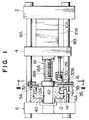
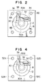
- Figs. 1 and 2 show a shutter-type clamping device in accordance with an embodiment of this invention.
- the components which are the same as or analogous to those of the above-described conventional example are indicated by the same reference numerals.
- the shutter 30 and the cylinder 32 for opening and closing the same are attached to the piston 12 through the intermediation of a guide plate 34.
- the shutter 30 is mainly composed of a shutter body 30A and a swing arm 30B.
- the swing arm 30B is rotatably supported by a shaft 36, around which it can make a swinging movement.
- the shaft 36 is attached to the piston 12 through the intermediation of a guide plate.
- the other end of this shaft 36 can slide in the axial direction by means of a guide 14A protruding from the clamping cylinder 14 and, at the same time, the shutter 30 and the cylinder 32 for driving the same are prevented from rotating with the piston 12.
- the mold thickness adjustment in this embodiment is effected by means of the protrusion 18.
- This protrusion 18 consists of a nut 18A and a screw bolt 18B, and the length of that portion of the screw bolt 18B protruding from the nut 18A is variable, whereby the mold thickness can be adjusted.
- the shutter drive cylinder 32 is driven to swing the shutter 30 as indicated by the dashed line of Fig. 2, thereby opening the hollow section 12A of the piston 12, so that the protrusion 18, which also serves as the mold thickness adjusting mechanism, can enter the hollow section 12A of the clamping piston 12.
- the movable platen 4 can be freely moved in the longitudinal direction by driving a moving cylinder 29.
- clamping piston 12 is at the left-hand (retreated) position as seen in the drawing.
- the movable platen 4 When performing clamping, the movable platen 4 is moved in the above-described state until the mold surfaces meet each other. Then, the shutter drive cylinder 32 makes a closing movement, bringing the shutter 30 to a position between the screw bolt 18B of the protrusion 18 and the hollow section 12A of the piston 12 (i.e., the position indicated by the solid line of Fig. 2). Afterwards, pressure oil is fed into a rear oil chamber 40 of the clamping cylinder 14, and the oil in a front oil chamber 42 is discharged to a tank, thereby causing the piston 12 to move forwards to be pressed against the protrusion 18 of the movable platen 4 through the shutter 30.
- the clamping piston 12 makes a forward or a backward movement in accordance with the clamping or the mold opening/closing movement. Since the shutter 30 and the shutter drive cylinder 32 are attached to the piston 12, the shutter 30 and the piston 12 are always united in their forward and backward movements, so that there is no risk of the shutter 30 and the piston 12 interfering with each other or of an excessive gap being generated, thus making it possible to perform shutter operation always in a smooth manner.
- the shutter and the members related thereto are independent of the other parts such as the tie bars, whereby the operational efficiency in the replacement or mounting of the shutter is greatly improved.
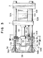
- Figs. 3 and 4 show another embodiment of this invention.
- the above-mentioned protrusion 18 is formed simply as a solid protrusion 50, with the mold thickness adjustment mechanism being provided as a separate component.
- screw sections 54A through 54D are provided at the ends of the tie bars 52A through 52D.
- Tie bar nuts 56A through 56D are engaged with these screw sections 54A through 54D, and, by turning these tie bar nuts 56A through 56D, the longitudinal position of the base plate 56 with respect to the tie bars 52A through 52D is adjusted.
- These tie bar nuts 56A through 56D are rotatably supported by the base plate 56.
- the tie bar nuts 56A through 56D are connected with each other through a timing belt 58 (or gears or the like), so that, by means of a single motor (not shown), all the tie bar nuts 56A through 56D can be simultaneously rotated in the same direction and by the same amount.
- the shutter drive cylinder 32 is also attached to the piston 12 through the intermediation of the guide plate 34, this guide plate 34 is not indispensable, either; the cylinder 32 may be directly attached to the piston 12.
- guide plates 34 and 38 are formed as separate components, it is also possible for them to constitute one component.
- the shutter is of a swing type, it may also be of a linear-reciprocation type. In that case, it is possible to provide a plate having a guide section for supporting the shutter in such a manner as to allow it to make a linear reciprocating movement. Alternatively, only the guide may be directly attached to the piston.
- the shutter and the drive mechanism thereof be directly or indirectly attached to the piston in such a manner as to be united with the piston in terms of movement, and that some means be provided which prevents the piston and the shutter mechanism from rotating with respect to the clamping cylinder.
Landscapes
- Engineering & Computer Science (AREA)
- Manufacturing & Machinery (AREA)
- Mechanical Engineering (AREA)
- Moulds For Moulding Plastics Or The Like (AREA)
Applications Claiming Priority (2)
| Application Number | Priority Date | Filing Date | Title |
|---|---|---|---|
| JP2270265A JP2793708B2 (ja) | 1990-10-08 | 1990-10-08 | シャッタ開閉タイプの型締装置 |
| JP270265/90 | 1990-10-08 |
Publications (3)
| Publication Number | Publication Date |
|---|---|
| EP0480351A1 true EP0480351A1 (de) | 1992-04-15 |
| EP0480351B1 EP0480351B1 (de) | 1995-06-14 |
| EP0480351B2 EP0480351B2 (de) | 1998-04-22 |
Family
ID=17483845
Family Applications (1)
| Application Number | Title | Priority Date | Filing Date |
|---|---|---|---|
| EP91117044A Expired - Lifetime EP0480351B2 (de) | 1990-10-08 | 1991-10-07 | Formschliessvorrichtung |
Country Status (4)
| Country | Link |
|---|---|
| US (1) | US5195431A (de) |
| EP (1) | EP0480351B2 (de) |
| JP (1) | JP2793708B2 (de) |
| DE (1) | DE69110393T3 (de) |
Cited By (1)
| Publication number | Priority date | Publication date | Assignee | Title |
|---|---|---|---|---|
| EP1025975A4 (de) * | 1998-08-25 | 2004-01-07 | Sodick Co Ltd | Formklemmvorrichtung für spritzgiessmaschinen und formöffnungskontrollverfahren dafür |
Families Citing this family (2)
| Publication number | Priority date | Publication date | Assignee | Title |
|---|---|---|---|---|
| JP3752806B2 (ja) * | 1997-09-26 | 2006-03-08 | 浅之助 千坂 | 射出圧縮成形装置 |
| EP2813342A1 (de) | 2009-11-30 | 2014-12-17 | Husky Injection Molding Systems S.A. | Gussformvorrichtung |
Citations (4)
| Publication number | Priority date | Publication date | Assignee | Title |
|---|---|---|---|---|
| US3737278A (en) * | 1971-02-25 | 1973-06-05 | Battenfeld Maschfab | Mould closing means |
| AT359228B (de) * | 1977-12-20 | 1980-10-27 | Battenfeld Maschfab | Formschliessvorrichtung, insbesondere an druck- giess- und/oder spritzgiessmaschinen fuer metalle und kunststoffe |
| EP0139771A2 (de) * | 1983-09-29 | 1985-05-08 | Karl Hehl | Formschliesseinheit einer Kunststoff-Spritzgiessmaschine |
| GB2151975A (en) * | 1983-12-21 | 1985-07-31 | Nissei Plastics Ind Co | Mould clamping apparatus |
Family Cites Families (1)
| Publication number | Priority date | Publication date | Assignee | Title |
|---|---|---|---|---|
| JPS5195929A (en) * | 1975-02-21 | 1976-08-23 | Shashutsuseikeikino katajimesochi |
-
1990
- 1990-10-08 JP JP2270265A patent/JP2793708B2/ja not_active Expired - Fee Related
-
1991
- 1991-10-07 EP EP91117044A patent/EP0480351B2/de not_active Expired - Lifetime
- 1991-10-07 DE DE69110393T patent/DE69110393T3/de not_active Expired - Fee Related
- 1991-10-07 US US07/772,292 patent/US5195431A/en not_active Expired - Fee Related
Patent Citations (4)
| Publication number | Priority date | Publication date | Assignee | Title |
|---|---|---|---|---|
| US3737278A (en) * | 1971-02-25 | 1973-06-05 | Battenfeld Maschfab | Mould closing means |
| AT359228B (de) * | 1977-12-20 | 1980-10-27 | Battenfeld Maschfab | Formschliessvorrichtung, insbesondere an druck- giess- und/oder spritzgiessmaschinen fuer metalle und kunststoffe |
| EP0139771A2 (de) * | 1983-09-29 | 1985-05-08 | Karl Hehl | Formschliesseinheit einer Kunststoff-Spritzgiessmaschine |
| GB2151975A (en) * | 1983-12-21 | 1985-07-31 | Nissei Plastics Ind Co | Mould clamping apparatus |
Cited By (1)
| Publication number | Priority date | Publication date | Assignee | Title |
|---|---|---|---|---|
| EP1025975A4 (de) * | 1998-08-25 | 2004-01-07 | Sodick Co Ltd | Formklemmvorrichtung für spritzgiessmaschinen und formöffnungskontrollverfahren dafür |
Also Published As
| Publication number | Publication date |
|---|---|
| DE69110393T3 (de) | 1998-10-08 |
| DE69110393T2 (de) | 1995-11-30 |
| US5195431A (en) | 1993-03-23 |
| DE69110393D1 (de) | 1995-07-20 |
| EP0480351B2 (de) | 1998-04-22 |
| JP2793708B2 (ja) | 1998-09-03 |
| JPH04146105A (ja) | 1992-05-20 |
| EP0480351B1 (de) | 1995-06-14 |
Similar Documents
| Publication | Publication Date | Title |
|---|---|---|
| US5135385A (en) | Clamping system | |
| US6517337B1 (en) | Injection molding machine having a modular construction which comprises a plurality of drive groups | |
| US6945765B2 (en) | Hydraulic clamping device for molding machines | |
| JP3240275B2 (ja) | 射出成形機の型締装置 | |
| US5238394A (en) | Mold clamping apparatus for molding apparatus | |
| JP4684675B2 (ja) | 型締装置 | |
| DE69421112T2 (de) | Roboter | |
| JP2645795B2 (ja) | スタックモ−ルドを備えた射出成形装置 | |
| US7316259B2 (en) | Diecasting machine | |
| JP3582826B2 (ja) | 型締装置における型締連係装置 | |
| EP0480351B1 (de) | Formschliessvorrichtung | |
| US5895670A (en) | Two-platen injection molding machine without tie bars | |
| DE102005004135B4 (de) | Formverklemmeinheit und -verfahren | |
| JP3927066B2 (ja) | 型締装置 | |
| DE4218822C2 (de) | Vorrichtung zum Auswerfen von Spritzgußteilen aus Spritzgußformen | |
| JPH11291311A (ja) | 射出成形機の型締装置 | |
| JP3917480B2 (ja) | 型締装置およびその作動方法 | |
| DE19544329A1 (de) | Einrichtung zum Spritzgießen von Kunststoffen | |
| JPH07112469A (ja) | 型締装置 | |
| US20030147989A1 (en) | Die clamping unit of an injection molding machine | |
| JPH10258451A (ja) | 射出成形機の型締装置 | |
| JP2610194B2 (ja) | スライドコア付き金型 | |
| WO2007031377A1 (de) | Spritzgiessmaschine | |
| AT524325B1 (de) | Einspritzaggregat für eine Formgebungsmaschine | |
| JPS6297820A (ja) | 複合式型締装置 |
Legal Events
| Date | Code | Title | Description |
|---|---|---|---|
| PUAI | Public reference made under article 153(3) epc to a published international application that has entered the european phase |
Free format text: ORIGINAL CODE: 0009012 |
|
| AK | Designated contracting states |
Kind code of ref document: A1 Designated state(s): AT BE CH DE DK ES FR GB GR IT LI LU NL SE |
|
| 17P | Request for examination filed |
Effective date: 19920730 |
|
| 17Q | First examination report despatched |
Effective date: 19940125 |
|
| GRAA | (expected) grant |
Free format text: ORIGINAL CODE: 0009210 |
|
| RBV | Designated contracting states (corrected) |
Designated state(s): DE GB |
|
| AK | Designated contracting states |
Kind code of ref document: B1 Designated state(s): DE GB |
|
| REF | Corresponds to: |
Ref document number: 69110393 Country of ref document: DE Date of ref document: 19950720 |
|
| PLBI | Opposition filed |
Free format text: ORIGINAL CODE: 0009260 |
|
| 26 | Opposition filed |
Opponent name: BATTENFELD GMBH Effective date: 19951016 |
|
| PLBF | Reply of patent proprietor to notice(s) of opposition |
Free format text: ORIGINAL CODE: EPIDOS OBSO |
|
| PLBF | Reply of patent proprietor to notice(s) of opposition |
Free format text: ORIGINAL CODE: EPIDOS OBSO |
|
| PLAW | Interlocutory decision in opposition |
Free format text: ORIGINAL CODE: EPIDOS IDOP |
|
| PLAW | Interlocutory decision in opposition |
Free format text: ORIGINAL CODE: EPIDOS IDOP |
|
| PUAH | Patent maintained in amended form |
Free format text: ORIGINAL CODE: 0009272 |
|
| STAA | Information on the status of an ep patent application or granted ep patent |
Free format text: STATUS: PATENT MAINTAINED AS AMENDED |
|
| 27A | Patent maintained in amended form |
Effective date: 19980422 |
|
| AK | Designated contracting states |
Kind code of ref document: B2 Designated state(s): DE GB |
|
| REG | Reference to a national code |
Ref country code: GB Ref legal event code: IF02 |
|
| PGFP | Annual fee paid to national office [announced via postgrant information from national office to epo] |
Ref country code: GB Payment date: 20021002 Year of fee payment: 12 |
|
| PGFP | Annual fee paid to national office [announced via postgrant information from national office to epo] |
Ref country code: DE Payment date: 20021011 Year of fee payment: 12 |
|
| PG25 | Lapsed in a contracting state [announced via postgrant information from national office to epo] |
Ref country code: GB Free format text: LAPSE BECAUSE OF NON-PAYMENT OF DUE FEES Effective date: 20031007 |
|
| PG25 | Lapsed in a contracting state [announced via postgrant information from national office to epo] |
Ref country code: DE Free format text: LAPSE BECAUSE OF NON-PAYMENT OF DUE FEES Effective date: 20040501 |
|
| GBPC | Gb: european patent ceased through non-payment of renewal fee |
Effective date: 20031007 |