EP0480392A2 - Dispositif pour signaler l'état de machines ou de processus - Google Patents
Dispositif pour signaler l'état de machines ou de processus Download PDFInfo
- Publication number
- EP0480392A2 EP0480392A2 EP91117177A EP91117177A EP0480392A2 EP 0480392 A2 EP0480392 A2 EP 0480392A2 EP 91117177 A EP91117177 A EP 91117177A EP 91117177 A EP91117177 A EP 91117177A EP 0480392 A2 EP0480392 A2 EP 0480392A2
- Authority
- EP
- European Patent Office
- Prior art keywords
- signalling device
- module
- modules
- light
- stack
- Prior art date
- Legal status (The legal status is an assumption and is not a legal conclusion. Google has not performed a legal analysis and makes no representation as to the accuracy of the status listed.)
- Withdrawn
Links
Images




Classifications
-
- F—MECHANICAL ENGINEERING; LIGHTING; HEATING; WEAPONS; BLASTING
- F21—LIGHTING
- F21V—FUNCTIONAL FEATURES OR DETAILS OF LIGHTING DEVICES OR SYSTEMS THEREOF; STRUCTURAL COMBINATIONS OF LIGHTING DEVICES WITH OTHER ARTICLES, NOT OTHERWISE PROVIDED FOR
- F21V3/00—Globes; Bowls; Cover glasses
-
- F—MECHANICAL ENGINEERING; LIGHTING; HEATING; WEAPONS; BLASTING
- F21—LIGHTING
- F21S—NON-PORTABLE LIGHTING DEVICES; SYSTEMS THEREOF; VEHICLE LIGHTING DEVICES SPECIALLY ADAPTED FOR VEHICLE EXTERIORS
- F21S8/00—Lighting devices intended for fixed installation
-
- F—MECHANICAL ENGINEERING; LIGHTING; HEATING; WEAPONS; BLASTING
- F21—LIGHTING
- F21V—FUNCTIONAL FEATURES OR DETAILS OF LIGHTING DEVICES OR SYSTEMS THEREOF; STRUCTURAL COMBINATIONS OF LIGHTING DEVICES WITH OTHER ARTICLES, NOT OTHERWISE PROVIDED FOR
- F21V17/00—Fastening of component parts of lighting devices, e.g. shades, globes, refractors, reflectors, filters, screens, grids or protective cages
- F21V17/10—Fastening of component parts of lighting devices, e.g. shades, globes, refractors, reflectors, filters, screens, grids or protective cages characterised by specific fastening means or way of fastening
- F21V17/104—Fastening of component parts of lighting devices, e.g. shades, globes, refractors, reflectors, filters, screens, grids or protective cages characterised by specific fastening means or way of fastening using feather joints, e.g. tongues and grooves, with or without friction
-
- F—MECHANICAL ENGINEERING; LIGHTING; HEATING; WEAPONS; BLASTING
- F21—LIGHTING
- F21V—FUNCTIONAL FEATURES OR DETAILS OF LIGHTING DEVICES OR SYSTEMS THEREOF; STRUCTURAL COMBINATIONS OF LIGHTING DEVICES WITH OTHER ARTICLES, NOT OTHERWISE PROVIDED FOR
- F21V17/00—Fastening of component parts of lighting devices, e.g. shades, globes, refractors, reflectors, filters, screens, grids or protective cages
- F21V17/10—Fastening of component parts of lighting devices, e.g. shades, globes, refractors, reflectors, filters, screens, grids or protective cages characterised by specific fastening means or way of fastening
- F21V17/16—Fastening of component parts of lighting devices, e.g. shades, globes, refractors, reflectors, filters, screens, grids or protective cages characterised by specific fastening means or way of fastening by deformation of parts; Snap action mounting
- F21V17/164—Fastening of component parts of lighting devices, e.g. shades, globes, refractors, reflectors, filters, screens, grids or protective cages characterised by specific fastening means or way of fastening by deformation of parts; Snap action mounting the parts being subjected to bending, e.g. snap joints
-
- G—PHYSICS
- G07—CHECKING-DEVICES
- G07C—TIME OR ATTENDANCE REGISTERS; REGISTERING OR INDICATING THE WORKING OF MACHINES; GENERATING RANDOM NUMBERS; VOTING OR LOTTERY APPARATUS; ARRANGEMENTS, SYSTEMS OR APPARATUS FOR CHECKING NOT PROVIDED FOR ELSEWHERE
- G07C3/00—Registering or indicating the condition or the working of machines or other apparatus, other than vehicles
-
- F—MECHANICAL ENGINEERING; LIGHTING; HEATING; WEAPONS; BLASTING
- F21—LIGHTING
- F21W—INDEXING SCHEME ASSOCIATED WITH SUBCLASSES F21K, F21L, F21S and F21V, RELATING TO USES OR APPLICATIONS OF LIGHTING DEVICES OR SYSTEMS
- F21W2111/00—Use or application of lighting devices or systems for signalling, marking or indicating, not provided for in codes F21W2102/00 – F21W2107/00
- F21W2111/02—Use or application of lighting devices or systems for signalling, marking or indicating, not provided for in codes F21W2102/00 – F21W2107/00 for roads, paths or the like
Definitions
- the present invention relates generally to signalling devices for indicating the operating status of machinery or processes and, more particularly, to such signalling devices that are elevated in order to enhance their visibility.
- Elevated signalling devices are well-known in factory-type environments where numerous industrial machines are present. Generally, such signalling devices are mounted on a pole so they are high above each machine and clearly visible from a distance. Each device typically has a plurality of differently colored lights for visually signalling the operating status of each machine.
- each of the lights is responsive to an operating status of the machine to which the device is connected.
- a typical device may have five lights colored clear, blue, red, amber and green.
- An illuminated clear light may indicate that it is time to change a component on the machine, while an illuminated green light may indicate the machine is operating in cycle.
- the relative positioning of the lights is usually insignificant because someone monitoring the device is usually too far away to distinguish the positions of the lights.
- the colors of the lights are very important, however, because even at a distance an illuminated light of one color is immediately distinguishable from the other lights of different colors.
- Elevated signalling devices are particularly effective in environments where the level of background noise is very high and there is a danger that an audible alarm will not be heard. Furthermore, the elevated signalling devices can distinguish between various malfunctioning conditions by relating different conditions to different colors of lights or to different frequencies of flashing lights. In a crowded factory, a system of elevated signalling devices enables maintenance people to quickly locate and identify specific problems in a large number of operating machines. Such a system is extremely effective and efficient because it enables a single individual to monitor a large number of machines from a distance where the operating status of all the machines can be simultaneously observed.
- An additional object of the present invention is to provide a signalling device having a plurality of stacked light modules that can be serviced without necessarily requiring the stack of modules to be disassembled.
- Another object of the present invention is to provide a signalling device comprising a plurality of stacked light modules that can be quickly and easily assembled or disassembled when necessary without the use of bolts or screws.
- a further object of the present invention is to provide a signalling device of stacked modules that is able to create a permanent record of conditions indicated by the lights of the device.
- the present invention contemplates a signalling device comprising a plurality of differently colored light modules stacked one above the other and having a communications bus comprising a plurality of channels that extends throughout the stack of light modules.
- Each light module is connected to and identified by a different one of the channels, thus enabling the light modules to be arranged in any order and still function properly.
- At least one cover plate on each of the light modules may be removed without requiring the light module to be removed from its stack. This feature enables both the interior of the light modules to be serviced and the color of the cover plates to be changed without requiring disassembly of the stack.
- a conventional data logger is connected to the device for recording the changing status of the lights, which in turn is indicative of a status of the machine or process being monitored.
- an exemplary environment for signalling device 14 of the invention includes an assembly line 10 having a plurality of machines 12.
- Each of the signalling devices 14 is associated with one of the machines 12 and is mounted atop a pole 16 high above the machine 12 so that the lights of the device are clearly visible at a distance.
- the pole 16 serves as means for supporting the signalling device 14 and also as a conduit for wiring between the machine 12 and the signalling device 14.
- a data logger 18 is connected to each signalling device 14 via wires in the pole 16.
- Each data logger is conventional and may, for example, be Model No. 740 by Keithley Scanning Co.
- signals from the machines 12 may also activate audio alarms if desired.
- This illustrated signalling device 14 has three identical light modules 20-22 stacked end-to-end, one above the other, as shown in FIG. 2. Other embodiments may have a smaller or larger number of light modules. Moreover, the signalling device 14 may have other orientations than that illustrated, such as being stacked horizontally instead of vertically. Each light module 20-22 of the signalling device 14 has differently colored transparent cover plates or lens 30-32. The light modules 20-22 are preferably constructed of sturdy plastic, such as polycarbonate. However, other suitable materials may be used.
- the cover plates 30-32 are preferably fluted lens - - i.e., lens having a horizontally rippled surface on the inside and a vertically rippled on the outside in order to disperse light waves produced by a light bulb 80 inside each of the light modules 20-22 so as to increase the visibility of the module.
- a base member 38 mounts the light modules 20-22 to the pole 16 and also interlinks wiring 40 from the machine 12 to the modules.
- the base 38 is preferably made of a metal such as zinc and is formed by conventional casting processes.
- the base 38 includes a plurality of external flanges 41 that collectively function as a heat sink to dissipate heat produced by a resistor 70 that reduces voltage supplied to the light modules 20-22 thus increasing bulb life.
- the resistor 70 functions as a voltage reducing element, and therefore, other embodiments may replace the resistor 70 with another type of voltage reducing element such as a Sidac (made by Motorola) or other semiconductor.
- the resistor 70 is secured to the base 38 by a receptacle 73 that enables heat to be directly transferred to the flanges 41.
- a signal bus having a plurality of channels extends through all of the light modules for the purpose of carrying signals to each of the modules.
- Each light module is responsive to the signals of one of the channels. Because the bus extends the length of the stacked modules, each module can be placed anywhere in the stack and, still function completely as intended.
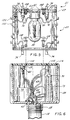
- FIG. 6 is a cross-sectional view of the base 38 illustrating its internal wiring.
- the base 38 includes a threaded receptacle for receiving a threaded end of the pole 16.
- Inside the pole 16 is a cable 60 containing the plurality of wires 40 provided from the machine 12.
- the wires 40 are connected to socket 62.
- Socket 62 contains pins 59, which each correspond to one of the channels 51-55, except one pin corresponds to a hot line 50 in the signal bus 42. Socket 62 begins the signal bus 42.
- a ground wire 64 is referenced to the base 38 by way of a ground bolt 66.
- Each light module 20-24 is identical except for two features: the color of the cover plates and the unique channels 51-55 to which light bulbs 80 in the light modules 20-24 are connected. Therefore, only the module 20 will be described in detail.
- the module 20 is illustrated in an exploded view in order to clearly show its structure.
- Each module is structurally identical to the module 20 and differs only electrically in that each module is responsive to a different one of the channels 51-55. They are all connected to hot line 50 since it provides a power source for the lights of the modules.
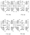
- FIGS. 8a-8e provide a detailed understanding of the alternative wiring schemes for the modules 20-24.
- Means for coupling partitions of the signal bus 42 located in the base 38 and the light module 20 are provided by plugs 74 in the module (FIG. 5) and sockets 62 in the base (FIG. 6).
- Contacts 63 of a light bulb socket 81 fit into indentation 65 on top plate 67 of the light module 20, thus enabling the light modules 20-24 to stack together evenly.
- the indentation 65 may be a hole in the top plate 67.
- the signal bus 42 extends from the base 38 through light module 20.
- An upper portion of FIG. 5 illustrates plugs 78 of the next light module 21 being coupled to sockets 76 of the light module 20. In this manner, the signal bus 42 continues to extend through the succession of stacked light modules 20-24. This important aspect of the invention provides for the unique module to illuminate regardless of its position in the stack.
- a standard color configuration for the signalling device may have five light modules colored clear, blue, red, amber and green. Each color may have a particular meaning in its application.
- the clear light module may indicate that it is time to change a component on the machine; the blue light module may indicate that three consecutive faulty parts have been produced; the red light module may indicate that the machine has stopped due to a fault; the amber light module may indicate that the machine is waiting for parts to be loaded or taken away; and the green light module may indicate that the machine is operating in cycle.
- a light module may also remain in a constantly lit mode or a flash mode when activated, wherein each of these modes indicates a specific operating status of a machine or process.
- FIG. 3 is an exploded view of the module 20 that more clearly shows the pins 86 of sockets 76, the plugs 74, and the plurality of channels 51-55 which make up the portion of the signal bus 42 in each module.
- the signal bus 42 in the illustrated embodiment includes one power line 50 and five machine-status lines 51-55. More generally, if n is the number of total lines, then up to (n - 1) modules may be used in the signalling device to provide a unique response for each machine status line. Although FIG. 1 only shows three light modules 20-22 in the signalling device 14, the illustrated embodiment has five channels 51-55 that will accommodate up to five light modules in a manner such that each module is responsive to a different one of the channels. Other embodiments having a different number of channels may provide for more or less light modules that may be arranged in any order and still function properly.
- FIGS. 8a-8e illustrates the light bulb socket 81 of the module 20 connected to different channels 51-55.
- the five alternative wiring schemes of FIGS. 8a-8e illustrate how five modules can be stacked end-to-end and provide a unique response to status signals from one of the machines 12. If each of the wiring schemes of FIGS. 8a-8e represents a different module, a stack of five modules may be assembled by joining the sockets and plugs to provide a signalling device wherein each module is uniquely responsive to one of the channels defining the machine status lines. Because of the signal bus structure of the device, the modules can be stacked in any order. For example, FIG.
- FIGS. 8a-8e illustrate a socket 81 being connected to a unique position in socket 76 for each one of the channels 52-55, respectively, while maintaining the connection to line 50.
- the signal bus in the illustrated, preferred embodiment employs a plurality of individual wires that each carry a unique status signal for a specific module. In other embodiments, however, the signal bus may be one wire (plus a return wire) common to all modules.
- This common line, or "party line” communicates serial data words that may be digital or analog, but each data word includes an address code to identify the module for which the data word was intended. The data words instruct the modules to activate or deactivate.
- each module has an address recognition means (ARM), such as a microprocessor or other decoding intelligence.
- ARM reads the address code of each received data word and determines if a data word is an instruction for that specific module, or if the received data word should be ignored. In this manner, all modules receive every communicated data word, but the ARM in each module determines if a module should respond to that data word.
- FIG. 9 illustrates a substantially complete wiring diagram for a signal bus utilizing a plurality of individual lines.
- FIG. 9 exemplifies a five-module embodiment wherein two of the light modules 21, 23 are continuously lit (on steady) when activated and two of the light modules 20, 22 flash when activated.
- FIG. 9 illustrates the signalling device with modules of all five possible configurations as shown in FIGS. 8a-8e. Each of the five possible configurations are embodied in one of the five modules 20-24 in FIG. 9. Because the machine 12 is providing only four (4) status signals to the signalling device 14, one of the five light modules is responsive to an unused channel (module 24) and is inoperative in the embodiment of FIG. 9.
- Dotted line 90 separates internal wiring of the signalling device 14 and a control system for the signalling device 14.
- the dotted line 90 represents the wiring 40 entering a bottom of the pole 16.
- a cap 92, the light modules 20-24 and the lines 50-55 are illustrated in a matrix format in order to clearly show the wiring scheme of the assembled device.
- each of the light bulb sockets 81 in light modules 20-24 is wired to hot wire 50 and one of the return channels 51-55.
- channels 51-55 may be hot wires and wire 50 the return.
- the resistor 70 serves to drop voltage from the power input 94 to each of the light modules 20-24. The resistor 70 steps the voltage down so as to increase the life of the bulbs 80 in the light modules 20-24 and to reduce frequency of maintenance.
- the two light modules 20, 22 have their return channels 51, 53 connected to the electronic flasher 72 in order to cause the light modules 20, 22 to flash when activated.
- light modules 21, 23 are directly connected to common return 96 to cause the light modules 21, 23 to remain constantly lit when activated.
- FIG. 9 also illustrates how an unused light module, here the clear light module 24, is connected in the signalling device 14.
- each of the light modules 20-24 may be serviced without requiring the stacked modules to be disassembled.
- transverse frame supports 98 of the light module frame include pairs of posts 100, 102 for securing the cover plates 30 to the frame of the light module 20.
- the cover plates are made of a material capable of yielding relatively easily, such as flexible plastic, which enables the cover plates 30 to slide over the posts 100, 102 and snap into place.
- apertures 104 on one side of the cover plate are first placed over widely spaced posts 102 on the transverse frame support 98 of the light module 20.
- the cover plate 30 is then pushed over the pair of posts 100 located on the opposite transverse frame support 98 of the other side of the light module 20.
- the faces of the posts are angled to gradually stretch the cover plate as it is pushed over the posts in order to mate the posts with apertures 104.
- the second cover plate 30 is attached to the light module 20 in the same fashion.
- FIG. 4 illustrates in phantom how the cover plate 30 yields radially as it is being attached to or removed from the transverse frame support 98 of the light module 20.
- a pry slot 106 is provided in one edge of the cover plate.
- a flat blade screwdriver is inserted into the pry slot 106 to radially expand the cover plate in the area of the pair of posts 100, sliding the cover plate off the posts and then lifting the cover plate 30 off the more widely spaced pair of posts 102.
- the other cover plate 30 of the module 20 is also equipped with a pry slot 106 and may be removed from the light module 20 in the same manner. After one cover plate 30 is removed, the internal components of the light module 20 are made readily accessible to a service person. The other cover plate retains the color identity of the light module during service.
- a service person is able to access all the internal components of a light module 20 without having to remove the light module 20 from its stacked arrangement in the signalling device 14. Furthermore, this feature enables the color of the light module 20 to be changed if desired without requiring the module to be removed from the signalling device 14. A service person simply removes the cover plates 30 and replaces them with new cover plates 30 of the desired color. Such a feature enables light modules 20-24 to be quickly and economically modified.
- the transverse frame support 98 is made of a transparent material such as clear plastic. Transparent frame supports 98 do not block light emitted from the light bulb 80, thus preventing a blind spot from being created between the light bulb 80 and a monitoring person.
- the light modules 20-24 are designed to utilize dilating rivets 108 enabling the signalling device 14 to be quickly and easily assembled or disassembled.
- the dilating rivets 108 are part No. SR-5075 manufactured by Richo Corporation of Chicago, Illinois.
- the dilating rivets 108 are designed to expand after they are inserted into mounting holes 110. Pressing down on a head of the rivet 108 causes a distal end of the dilating rivet to expand and secure the rivet 108 in the mounting hole 110.
- the bottom light module 20 is attached to the base 38 by first coupling the plugs 74 of the light module 20 into the sockets 62 of the base 38, making sure that the pins 59 of the sockets 62 align correctly with the corresponding holes of the plugs 74. Once the corresponding plugs 74 and sockets 62 are connected, the light module 20 is secured to the base 38 by inserting a dilating rivet 110 into each of the mounting holes 110 and then pressing down on the head of each dilating rivet 108 in order to expand the distal ends and secure each rivet 108 in a mounting hole 110.
- a second light module 21 is secured to the bottom light module 20 in the same manner as the bottom light module 20 is secured to the base 38. This sequence is repeated until all the light modules are secured to form the signalling device 14.
- the order the light modules 20-24 are stacked does not effect their functioning properly as long as the desired cover plates are attached to a light module of the proper channel. If not, the desired color of cover plates may be easily replaced as discussed above.
- the cap 92 is secured to the top of the stack. The cap 92 functions to protect the top light module 22 and provide the signalling device 14 with a finished look. Snap rivets 109 are molded into the cap 92 for fastening the cap 92 to the mounting holes 110 in the top of the uppermost light module (see FIG. 2).
- the cover plates 30-32 are removed from the light module frames according to the previously discussed technique.
- the dilating rivets 108 may be disassembled by first gently prying up the head of each rivet 108 with a flat blade screwdriver in order to contract the distal ends, and then removing each rivet 110 from the mounting holes 110.
- the cap 92 also can be removed by gently prying up the snap rivets 109.
- the base 38 may be serviced by unscrewing the four flat head screws 112 that secure the base top 114 to the base 38.
- a separate data logger 18 may be provided for each signalling device 14.
- the data logger 18 automatically records on/off time of each of the light modules 20-24 (FIG. 9) and activation time of each module. In this manner, a person is not required to waste his or her time by manually recording activity of the signalling device 14 and hence machine or process time.
- data logger 18 automatically prints out an activity record 19 of its corresponding signalling device 14 and the service person simply collects the printouts from each data logger 18 at the end of each day.
- the data loggers 18 enable accurate records to be made of signalling device activity while allowing service persons to make more efficient use of their time.
Landscapes
- Engineering & Computer Science (AREA)
- General Engineering & Computer Science (AREA)
- Physics & Mathematics (AREA)
- General Physics & Mathematics (AREA)
- Arrangement Of Elements, Cooling, Sealing, Or The Like Of Lighting Devices (AREA)
- Circuit Arrangement For Electric Light Sources In General (AREA)
- Illuminated Signs And Luminous Advertising (AREA)
Applications Claiming Priority (2)
| Application Number | Priority Date | Filing Date | Title |
|---|---|---|---|
| US07/595,209 US5103215A (en) | 1990-10-10 | 1990-10-10 | Device for signalling status of machines or processes |
| US595209 | 1990-10-10 |
Publications (2)
| Publication Number | Publication Date |
|---|---|
| EP0480392A2 true EP0480392A2 (fr) | 1992-04-15 |
| EP0480392A3 EP0480392A3 (en) | 1992-12-02 |
Family
ID=24382229
Family Applications (1)
| Application Number | Title | Priority Date | Filing Date |
|---|---|---|---|
| EP19910117177 Withdrawn EP0480392A3 (en) | 1990-10-10 | 1991-10-09 | Device for signalling status of machines or processes |
Country Status (5)
| Country | Link |
|---|---|
| US (1) | US5103215A (fr) |
| EP (1) | EP0480392A3 (fr) |
| JP (1) | JPH04314087A (fr) |
| CA (1) | CA2053053C (fr) |
| MX (1) | MX9101513A (fr) |
Cited By (6)
| Publication number | Priority date | Publication date | Assignee | Title |
|---|---|---|---|---|
| GB2344200A (en) * | 1998-11-26 | 2000-05-31 | Schneider Electric Ind Sa | Signalling device |
| EP1239214A3 (fr) * | 2001-03-10 | 2005-04-06 | Karl Jautz Elektrotechnische Spezialfabrik KG | Colonne de signalisation lumineuse |
| AT501053B1 (de) * | 2004-12-22 | 2006-06-15 | Auer Fabrik Elek Scher Maschin | Warnlichtsäule |
| WO2006066300A1 (fr) * | 2004-12-22 | 2006-06-29 | J. Auer - Fabrik Elektrischer Maschinen Gesellschaft M.B.H. | Colonne lumineuse d'avertissement |
| EP2141443A3 (fr) * | 2008-07-03 | 2012-05-09 | Rheinmetall Landsysteme GmbH | Affichage de l'état d'une station d'armement ou d'un système d'arme |
| WO2016154042A1 (fr) * | 2015-03-20 | 2016-09-29 | Federal Signal Corporation | Système d'avertissement à sous-systèmes modularisés |
Families Citing this family (14)
| Publication number | Priority date | Publication date | Assignee | Title |
|---|---|---|---|---|
| US5736942A (en) * | 1996-07-25 | 1998-04-07 | Randolph; Glenn Edgar | Key pad for communicating with a microprocessor |
| US5963126A (en) * | 1997-02-27 | 1999-10-05 | Star Headlight And Lantern Co, Inc | Visual signaling device |
| AU6442598A (en) * | 1997-02-27 | 1998-09-18 | Star Headlight & Lantern Co., Inc. | Visual signaling device |
| US5898380A (en) * | 1997-07-10 | 1999-04-27 | Chi; Yu-Tsang | Shock endurable alarm lamp |
| DE19854666C2 (de) * | 1998-11-26 | 2003-01-02 | Schneider Electric Gmbh | Signaleinrichtung |
| US6626557B1 (en) | 1999-12-29 | 2003-09-30 | Spx Corporation | Multi-colored industrial signal device |
| DE10343529A1 (de) * | 2003-09-19 | 2005-04-21 | Pepperl & Fuchs | Vorrichtung zur optischen Übermittlung von Information |
| FR2869975B1 (fr) * | 2004-05-04 | 2006-06-16 | Schneider Electric Ind Sas | Colonne de signalisation verrouillable |
| FR2905501A1 (fr) * | 2006-08-31 | 2008-03-07 | Neopost Technologies Sa | Machine a affranchir pour ligne d'insertion d'enveloppes a haute cadence |
| JP2014112524A (ja) | 2012-11-12 | 2014-06-19 | Ricoh Co Ltd | 非水電解液蓄電素子 |
| DE102014114111A1 (de) * | 2014-09-29 | 2016-03-31 | Werma Holding Gmbh + Co. Kg | Optisches Signalgerät |
| US20160097493A1 (en) * | 2014-10-02 | 2016-04-07 | Taylor W. Anderson | Method and apparatus for a lighting assembly with an integrated auxiliary electronic component port |
| CN110118397A (zh) * | 2018-02-06 | 2019-08-13 | 富泰华工业(深圳)有限公司 | 空气净化装置 |
| TWI853515B (zh) * | 2023-03-30 | 2024-08-21 | 啓碁科技股份有限公司 | 具有光指示功能之電子裝置 |
Family Cites Families (15)
| Publication number | Priority date | Publication date | Assignee | Title |
|---|---|---|---|---|
| US3299264A (en) * | 1964-08-28 | 1967-01-17 | Willis L Lipscomb | End plate for lighting fixtures |
| FR1526306A (fr) * | 1967-04-14 | 1968-05-24 | Schlumberger Cie N | Dispositif électrique de signalisation |
| US3555543A (en) * | 1969-09-29 | 1971-01-12 | Bell Telephone Labor Inc | Modular visual indicator having interlocking indicator base modules |
| FR2128998A5 (fr) * | 1971-03-10 | 1972-10-27 | Telemecanique Electrique | |
| US3818439A (en) * | 1972-04-11 | 1974-06-18 | Work Area Protection Corp | Warning light assembly with modularized inserts |
| FR2196101A5 (fr) * | 1972-08-08 | 1974-03-08 | Elfverson Goran | |
| JPS5029150U (fr) * | 1973-07-13 | 1975-04-02 | ||
| US4017831A (en) * | 1976-03-15 | 1977-04-12 | The Boeing Company | N/C machine paging, status and report system |
| JPS53135176A (en) * | 1977-04-28 | 1978-11-25 | Fukuba Kogyo Kk | Manual cleaner |
| US4364105A (en) * | 1979-05-03 | 1982-12-14 | Esquire, Inc. | Stacked fixtures with angularly positioned lamps and downwardly light-directing reflectors |
| US4399434A (en) * | 1981-06-08 | 1983-08-16 | Bielat Norbert J | Line indicating apparatus |
| FR2517021B1 (fr) * | 1981-11-23 | 1986-09-05 | Telemecanique Electrique | Colonne lumineuse |
| US4668935A (en) * | 1982-12-22 | 1987-05-26 | Mcdermott Julian A | Visual alarm reliability assurance system |
| JPS60196624A (ja) * | 1984-03-19 | 1985-10-05 | Nissin Electric Co Ltd | デ−タロガ |
| JP2724492B2 (ja) * | 1989-02-08 | 1998-03-09 | 株式会社エスジー | データロガー |
-
1990
- 1990-10-10 US US07/595,209 patent/US5103215A/en not_active Expired - Fee Related
-
1991
- 1991-10-09 CA CA002053053A patent/CA2053053C/fr not_active Expired - Fee Related
- 1991-10-09 JP JP3262421A patent/JPH04314087A/ja active Pending
- 1991-10-09 EP EP19910117177 patent/EP0480392A3/en not_active Withdrawn
- 1991-10-10 MX MX9101513A patent/MX9101513A/es unknown
Cited By (9)
| Publication number | Priority date | Publication date | Assignee | Title |
|---|---|---|---|---|
| GB2344200A (en) * | 1998-11-26 | 2000-05-31 | Schneider Electric Ind Sa | Signalling device |
| FR2786592A1 (fr) * | 1998-11-26 | 2000-06-02 | Schneider Electric Ind Sa | Appareil de signalisation des etats de fonctionnement de machines |
| GB2344200B (en) * | 1998-11-26 | 2003-09-24 | Schneider Electric Ind Sa | Signalling device |
| EP1239214A3 (fr) * | 2001-03-10 | 2005-04-06 | Karl Jautz Elektrotechnische Spezialfabrik KG | Colonne de signalisation lumineuse |
| AT501053B1 (de) * | 2004-12-22 | 2006-06-15 | Auer Fabrik Elek Scher Maschin | Warnlichtsäule |
| WO2006066300A1 (fr) * | 2004-12-22 | 2006-06-29 | J. Auer - Fabrik Elektrischer Maschinen Gesellschaft M.B.H. | Colonne lumineuse d'avertissement |
| EP2141443A3 (fr) * | 2008-07-03 | 2012-05-09 | Rheinmetall Landsysteme GmbH | Affichage de l'état d'une station d'armement ou d'un système d'arme |
| WO2016154042A1 (fr) * | 2015-03-20 | 2016-09-29 | Federal Signal Corporation | Système d'avertissement à sous-systèmes modularisés |
| US9886832B2 (en) | 2015-03-20 | 2018-02-06 | Federal Signal Corporation | Warning system devices |
Also Published As
| Publication number | Publication date |
|---|---|
| EP0480392A3 (en) | 1992-12-02 |
| JPH04314087A (ja) | 1992-11-05 |
| CA2053053C (fr) | 1997-06-03 |
| US5103215A (en) | 1992-04-07 |
| MX9101513A (es) | 1992-06-05 |
| CA2053053A1 (fr) | 1992-04-11 |
Similar Documents
| Publication | Publication Date | Title |
|---|---|---|
| CA2053053C (fr) | Dispositif de signalisation d'etat de machines ou de procedes | |
| US12478010B2 (en) | Integrated ceiling device with mechanical arrangement for a light source | |
| CA2653899C (fr) | Barre lumineuse | |
| US4617614A (en) | Electric light fixture | |
| US5539623A (en) | Lighting device used in an exit sign | |
| US20030030567A1 (en) | Flexible functionality of stack light | |
| US6457270B1 (en) | Universal emergency sign | |
| EP1113215A2 (fr) | Dispositif de signalisation industriel multicolore | |
| US7905640B2 (en) | Light bar and method for making | |
| US20180266722A1 (en) | Illumination grille and assembly method | |
| US5803589A (en) | Ceiling lighting fixture | |
| US3868682A (en) | Light column having stacked elements | |
| US20220381429A1 (en) | Ceiling fan with ceiling projection function | |
| US20220146064A1 (en) | Lighting fixtures with led modules configured for tool-less attachment | |
| WO2006031487A2 (fr) | Indicateur visuel multicolore, a etats multiples, antideflagrant | |
| JPH0439235B2 (fr) | ||
| KR200484595Y1 (ko) | 배전반용 조명기구 | |
| WO2004086321A2 (fr) | Indicateur lumineux d'appel infirmier | |
| CN210955412U (zh) | 一种物联网防火墙报警装置 | |
| KR20180085959A (ko) | 수배전반용 안전 관리 장치 | |
| CN222233109U (zh) | 一种消防警报装置 | |
| CN209835373U (zh) | 一种便于检修的电梯轿厢 | |
| JPH0227291U (fr) | ||
| JP2531168Y2 (ja) | 信号灯 | |
| EP3399534B1 (fr) | Ensemble de montage de del et/ou d'unités de contact et unités à del pour circuits de commande électriques d'installations industrielles |
Legal Events
| Date | Code | Title | Description |
|---|---|---|---|
| PUAI | Public reference made under article 153(3) epc to a published international application that has entered the european phase |
Free format text: ORIGINAL CODE: 0009012 |
|
| AK | Designated contracting states |
Kind code of ref document: A2 Designated state(s): DE ES FR IT |
|
| PUAL | Search report despatched |
Free format text: ORIGINAL CODE: 0009013 |
|
| AK | Designated contracting states |
Kind code of ref document: A3 Designated state(s): DE ES FR IT |
|
| 17P | Request for examination filed |
Effective date: 19930529 |
|
| STAA | Information on the status of an ep patent application or granted ep patent |
Free format text: STATUS: THE APPLICATION IS DEEMED TO BE WITHDRAWN |
|
| 18D | Application deemed to be withdrawn |
Effective date: 19940503 |