EP0480443A2 - Dispositif de fixation pour tube flexible - Google Patents
Dispositif de fixation pour tube flexible Download PDFInfo
- Publication number
- EP0480443A2 EP0480443A2 EP91117327A EP91117327A EP0480443A2 EP 0480443 A2 EP0480443 A2 EP 0480443A2 EP 91117327 A EP91117327 A EP 91117327A EP 91117327 A EP91117327 A EP 91117327A EP 0480443 A2 EP0480443 A2 EP 0480443A2
- Authority
- EP
- European Patent Office
- Prior art keywords
- ring
- fastening
- stationary ring
- flexible tube
- wall part
- Prior art date
- Legal status (The legal status is an assumption and is not a legal conclusion. Google has not performed a legal analysis and makes no representation as to the accuracy of the status listed.)
- Withdrawn
Links
Images



Classifications
-
- F—MECHANICAL ENGINEERING; LIGHTING; HEATING; WEAPONS; BLASTING
- F16—ENGINEERING ELEMENTS AND UNITS; GENERAL MEASURES FOR PRODUCING AND MAINTAINING EFFECTIVE FUNCTIONING OF MACHINES OR INSTALLATIONS; THERMAL INSULATION IN GENERAL
- F16F—SPRINGS; SHOCK-ABSORBERS; MEANS FOR DAMPING VIBRATION
- F16F9/00—Springs, vibration-dampers, shock-absorbers, or similarly-constructed movement-dampers using a fluid or the equivalent as damping medium
- F16F9/32—Details
- F16F9/38—Covers for protection or appearance
-
- B—PERFORMING OPERATIONS; TRANSPORTING
- B60—VEHICLES IN GENERAL
- B60G—VEHICLE SUSPENSION ARRANGEMENTS
- B60G15/00—Resilient suspensions characterised by arrangement, location or type of combined spring and vibration damper, e.g. telescopic type
- B60G15/02—Resilient suspensions characterised by arrangement, location or type of combined spring and vibration damper, e.g. telescopic type having mechanical spring
- B60G15/06—Resilient suspensions characterised by arrangement, location or type of combined spring and vibration damper, e.g. telescopic type having mechanical spring and fluid damper
- B60G15/062—Resilient suspensions characterised by arrangement, location or type of combined spring and vibration damper, e.g. telescopic type having mechanical spring and fluid damper the spring being arranged around the damper
- B60G15/063—Resilient suspensions characterised by arrangement, location or type of combined spring and vibration damper, e.g. telescopic type having mechanical spring and fluid damper the spring being arranged around the damper characterised by the mounting of the spring on the damper
-
- B—PERFORMING OPERATIONS; TRANSPORTING
- B60—VEHICLES IN GENERAL
- B60G—VEHICLE SUSPENSION ARRANGEMENTS
- B60G15/00—Resilient suspensions characterised by arrangement, location or type of combined spring and vibration damper, e.g. telescopic type
- B60G15/02—Resilient suspensions characterised by arrangement, location or type of combined spring and vibration damper, e.g. telescopic type having mechanical spring
- B60G15/06—Resilient suspensions characterised by arrangement, location or type of combined spring and vibration damper, e.g. telescopic type having mechanical spring and fluid damper
- B60G15/067—Resilient suspensions characterised by arrangement, location or type of combined spring and vibration damper, e.g. telescopic type having mechanical spring and fluid damper characterised by the mounting on the vehicle body or chassis of the spring and damper unit
- B60G15/068—Resilient suspensions characterised by arrangement, location or type of combined spring and vibration damper, e.g. telescopic type having mechanical spring and fluid damper characterised by the mounting on the vehicle body or chassis of the spring and damper unit specially adapted for MacPherson strut-type suspension
-
- B—PERFORMING OPERATIONS; TRANSPORTING
- B60—VEHICLES IN GENERAL
- B60G—VEHICLE SUSPENSION ARRANGEMENTS
- B60G2200/00—Indexing codes relating to suspension types
- B60G2200/40—Indexing codes relating to the wheels in the suspensions
- B60G2200/46—Indexing codes relating to the wheels in the suspensions camber angle
-
- B—PERFORMING OPERATIONS; TRANSPORTING
- B60—VEHICLES IN GENERAL
- B60G—VEHICLE SUSPENSION ARRANGEMENTS
- B60G2202/00—Indexing codes relating to the type of spring, damper or actuator
- B60G2202/30—Spring/Damper and/or actuator Units
- B60G2202/31—Spring/Damper and/or actuator Units with the spring arranged around the damper, e.g. MacPherson strut
- B60G2202/312—The spring being a wound spring
-
- B—PERFORMING OPERATIONS; TRANSPORTING
- B60—VEHICLES IN GENERAL
- B60G—VEHICLE SUSPENSION ARRANGEMENTS
- B60G2204/00—Indexing codes related to suspensions per se or to auxiliary parts
- B60G2204/10—Mounting of suspension elements
- B60G2204/12—Mounting of springs or dampers
- B60G2204/124—Mounting of coil springs
-
- B—PERFORMING OPERATIONS; TRANSPORTING
- B60—VEHICLES IN GENERAL
- B60G—VEHICLE SUSPENSION ARRANGEMENTS
- B60G2204/00—Indexing codes related to suspensions per se or to auxiliary parts
- B60G2204/10—Mounting of suspension elements
- B60G2204/12—Mounting of springs or dampers
- B60G2204/124—Mounting of coil springs
- B60G2204/1242—Mounting of coil springs on a damper, e.g. MacPerson strut
-
- B—PERFORMING OPERATIONS; TRANSPORTING
- B60—VEHICLES IN GENERAL
- B60G—VEHICLE SUSPENSION ARRANGEMENTS
- B60G2204/00—Indexing codes related to suspensions per se or to auxiliary parts
- B60G2204/10—Mounting of suspension elements
- B60G2204/12—Mounting of springs or dampers
- B60G2204/128—Damper mount on vehicle body or chassis
-
- B—PERFORMING OPERATIONS; TRANSPORTING
- B60—VEHICLES IN GENERAL
- B60G—VEHICLE SUSPENSION ARRANGEMENTS
- B60G2204/00—Indexing codes related to suspensions per se or to auxiliary parts
- B60G2204/40—Auxiliary suspension parts; Adjustment of suspensions
- B60G2204/418—Bearings, e.g. ball or roller bearings
-
- B—PERFORMING OPERATIONS; TRANSPORTING
- B60—VEHICLES IN GENERAL
- B60G—VEHICLE SUSPENSION ARRANGEMENTS
- B60G2204/00—Indexing codes related to suspensions per se or to auxiliary parts
- B60G2204/40—Auxiliary suspension parts; Adjustment of suspensions
- B60G2204/43—Fittings, brackets or knuckles
-
- B—PERFORMING OPERATIONS; TRANSPORTING
- B60—VEHICLES IN GENERAL
- B60G—VEHICLE SUSPENSION ARRANGEMENTS
- B60G2204/00—Indexing codes related to suspensions per se or to auxiliary parts
- B60G2204/40—Auxiliary suspension parts; Adjustment of suspensions
- B60G2204/44—Centering or positioning means
-
- B—PERFORMING OPERATIONS; TRANSPORTING
- B60—VEHICLES IN GENERAL
- B60G—VEHICLE SUSPENSION ARRANGEMENTS
- B60G2204/00—Indexing codes related to suspensions per se or to auxiliary parts
- B60G2204/40—Auxiliary suspension parts; Adjustment of suspensions
- B60G2204/44—Centering or positioning means
- B60G2204/4404—Retainers for holding a fixing element, e.g. bushing, nut, bolt etc., until it is tightly fixed in position
-
- B—PERFORMING OPERATIONS; TRANSPORTING
- B60—VEHICLES IN GENERAL
- B60G—VEHICLE SUSPENSION ARRANGEMENTS
- B60G2204/00—Indexing codes related to suspensions per se or to auxiliary parts
- B60G2204/40—Auxiliary suspension parts; Adjustment of suspensions
- B60G2204/45—Stops limiting travel
- B60G2204/4502—Stops limiting travel using resilient buffer
-
- B—PERFORMING OPERATIONS; TRANSPORTING
- B60—VEHICLES IN GENERAL
- B60G—VEHICLE SUSPENSION ARRANGEMENTS
- B60G2204/00—Indexing codes related to suspensions per se or to auxiliary parts
- B60G2204/40—Auxiliary suspension parts; Adjustment of suspensions
- B60G2204/46—Means for locking the suspension
-
- B—PERFORMING OPERATIONS; TRANSPORTING
- B60—VEHICLES IN GENERAL
- B60G—VEHICLE SUSPENSION ARRANGEMENTS
- B60G2204/00—Indexing codes related to suspensions per se or to auxiliary parts
- B60G2204/61—Adjustable during maintenance
-
- Y—GENERAL TAGGING OF NEW TECHNOLOGICAL DEVELOPMENTS; GENERAL TAGGING OF CROSS-SECTIONAL TECHNOLOGIES SPANNING OVER SEVERAL SECTIONS OF THE IPC; TECHNICAL SUBJECTS COVERED BY FORMER USPC CROSS-REFERENCE ART COLLECTIONS [XRACs] AND DIGESTS
- Y10—TECHNICAL SUBJECTS COVERED BY FORMER USPC
- Y10T—TECHNICAL SUBJECTS COVERED BY FORMER US CLASSIFICATION
- Y10T403/00—Joints and connections
- Y10T403/32—Articulated members
- Y10T403/32606—Pivoted
- Y10T403/32631—Universal ball and socket
- Y10T403/32729—Externally packed
Definitions
- the present invention relates to a bracket to be used exclusively for fixing to a prescribed member a flexible tube such as the protective boot installed in an automobile suspension device, for example.
- the automobile suspension devices come in several types and are represented by those of the strut type.
- the suspension device of the strut type is so constructed that a lower receiving plate is fixed to the upper terminal part of a dumper case, an upper receiving plate is rotatably disposed on the upper terminal part of a piston rod adapted to slide inside the dumper case, a compression coil spring is interposed between the upper and lower receiving plates, a protective boot made of rubber is wrapped around the projected periphery of the piston rod, and the upper terminal part of the protective boot is fixed on the side of the upper receiving plate.
- the protective boot is fixed on the side of the upper terminal part thereof to the upper receiving plate and is not fixed but left free on the side of the lover terminal part thereof.
- the protective boot is required to be fixed additionally on the side of the lower terminal part thereof to the upper side of the dumper case and consequently to be allowed to close the open region so as to protect the sealed surfaces against access thereto of the dirt, dust, etc.
- the compression coil spring is expanded or contracted proportionately to the slide motion of the piston rod inside the dumper case to allow the wheel to move vertically.
- the compression coil spring is suffered to twist and, as a result, the upper receiving plate supporting the compression coil spring thereon is synchronously rotated in the same direction.
- the protective boot in the light of this structural characteristic, is so constructed as to be fixed not only on the side of the upper terminal part thereof but also on the side of the lover terminal part thereof, then in consequence of this fixation on the side of the lover terminal part thereof, the rotation of the upper receiving plate synchronized with the twisting of the compression coil spring causes the upper terminal part of the protective boot fixed to the upper receiving plate to be automatically twisted in the same direction.
- the upper terminal part of the protective boot will fatigue and sustain breakage owing to the sympathetic twist of the upper terminal part of the protective boot.
- the primary object of the present invention which has been developed to fulfill the demand is to provide a novel fixing bracket which prevents the terminal parts of a flexible tube from being twisted in consequence of the rotation of a pertinent member and precludes the possibility of the terminal parts of the flexible tube being broken through fatigue.
- a fixing bracket which comprises a stationary ring fixed on the side of a prescribed member, a spacer ring fitted to the stationary ring and a fastening ring fitted to the spacer ring for fastening a terminal part of a flexible tube, the spacer ring being provided with resilient supporting arms capable of rotatably supporting the fastening ring, the fastening ring being rotatably retained in place on the stationary ring via the spacer ring by virtue of the resilient force of the resilient supporting arms.
- a fixing bracket comprising a stationary ring fixed on the side of a prescribed member and a fastening ring fitted to a terminal part of a flexible tube, the stationary ring being provided with resilient supporting arms capable of rotatably supporting the fastening ring, the fastening ring being rotatably retained in place directly on the stationary ring by virtue of the resilient force of the resilient supporting arms.
- FIG. 1 is a cross sectional view illustrating the essential part of a suspension device in which one embodiment of the fixing bracket according to the present invention is used.
- FIG. 2 is a perspective view illustrating the fixing bracket in an exploded state.
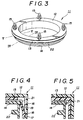
- FIG. 3 is a perspective view illustrating the fixing bracket in an assembled state.
- FIG. 4 is a cross sectional view taken along line IV-IV in FIG. 3.
- FIG. 5 is a cross sectional view taken along line V-V in FIG. 3.
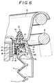
- FIG. 6 is an enlarged, partially cutaway, cross sectional view illustrating the fixing bracket which has the upper terminal part of a protective boot fixed to an upper receiving plate.
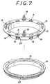
- FIG. 7 is an exploded perspective view illustrating another embodiment of the fixing bracket according to the present invention.
- FIG. 8 is a cross sectional view illustrating the fixing bracket of FIG. 7, but in an assembled state cut at a position of a resilient supporting arm thereof.
- FIG. 9 is a cross sectional view illustrating the fixing bracket of FIG. 7, but in an assembled state cut at a position of a resilient engaging leg thereof.
- the fixing bracket involved in the first embodiment illustrated in FIGS. 1 to 6 has been developed for the purpose of fastening the upper terminal part of a protective boot which is installed in an automobile suspension device.
- This suspension device is of the strut type. As illustrated in FIG. 1, this suspension device is so constructed that a lower receiving plate 3 is fixed to the upper terminal part of a dumper case 1, an upper receiving plate 4 is rotatably disposed through a bearing 5 on the dumper case 1, a compression coil spring 6 is interposed between the upper and lower receiving plates 3 and 4, and a protective boot 7 is wrapped around the projecting periphery of the piston rod 2.
- reference numeral 8 stands for a dumper rubber member inserted in the upper part of the piston rod 2 and numeral 9 for a hydraulic pipe connected to the interior of the dumper case 1 through the interior of the piston rod 2.
- the bracket 11 is composed of three parts, i.e. stationary ring 12 formed in a cross section roughly of the shape of the letter L, a spacer ring 13 and a fastening ring 14 all made of synthetic resin.
- the stationary ring 12 is so constructed that a plurality of resilient engaging legs 15 adapted to be fastened to as many engaging holes H bored in the upper receiving plate 4 are integrally projected from a horizontal wall part, depressed parts 16 of a prescribed width are formed equidistantly in the outer side of a vertical wall part, and lock claws 17 are formed one each along the lower edges of the depressed part 16.
- the spacer ring 13 is so constructed that a plurality of engaging claws 18 adapted to plunge into the depressed parts 16 of the stationary ring 12 and engage with the lock claws 17 are integrally formed inside the lower part of a vertical wall part and a plurality of outwardly projecting resilient supporting arms 19 extend aslant through an empty space from the engaging claws 18 in a vertical wall part.
- the fastening ring 14 is so constructed that an annular shoulder part 21 adapted to be rotatably supported on the terminal edges of the resilient supporting arms 19 is formed projectingly along the inner terminal edge of a horizontal wall part and, at the same time, an annular hooking part 22 adapted to catch hold of the upper terminal part 7a of the protective boot 7 is integrally projected from the outside of the vertical wall part.
- the attachment of the upper terminal part 7a of the protective boot 7 to the upper receiving plate 4 by the use of the fixing bracket 11 constructed as described above is accomplished by causing the upper terminal part 7a of the protective boot 7 to be caught on the annular hooking part 22 and consequently enabling the protective boot 7 to be readily fastened to the fixing bracket 11 and thereafter forcing the resilient engaging legs 15 formed on the stationary ring 12 of the fixing bracket 11 into engagement with the corresponding engaging holes H of the upper receiving plate 4.
- the fixing bracket 11 is secured fast to the upper receiving plate 4 and, at the same time, the upper terminal part 7a of the protective boot 7 is attached infallibly, though indirectly, to the upper receiving plate 4 as illustrated in FIG. 1 and FIG. 6.
- the illustrated suspension device is so constructed that when the lower terminal part 7b of the protective boot 7 is retained in place by a retaining part 10 disposed fast on the upper terminal part of the dumper case 1, the lower terminal part 7b of the protective boot 7 is consequently fixed and the region which would remain open in the conventional suspension device is closed.
- the upper terminal part 7a of the protective boot 7 is attached to the upper receiving plate 4 through the fixing bracket 11, only the stationary ring 12 and the spacer ring 13 of the fixing bracket 11 are rotated jointly with the upper receiving plate 4 when the upper receiving plate 4 is rotated synchronously with the twisting of the compression coil spring 6.
- the fastening ring 14 which fastens the protective boot 7 merely allows synchronous rotation of these rings 12 and 13 and does not allow itself to be jointly rotated therewith.
- the fastening ring 14 is retained in place on the stationary ring 12 by virtue of the resilient force derived from the resilient supporting arms 19 of the spacer ring 13, of course, ensures smooth relative rotation between the stationary ring 12 and the fastening ring 14, allows efficient absorption of the vibration on the side of the protective boot 7 by the flexion of the resilient supporting arms 19, and warrants efficient absorption of dimensional error between the fastening ring 14 and the spacer ring 13.
- the fixing bracket 11 of the second embodiment also has been developed for the purpose of fastening the upper terminal 7a of the protective boot 7 installed in the aforementioned automobile suspension device, but is characterized by decreasing the number of the component parts to two, i.e. a stationary ring 12 and a fastening ring 14 as illustrated in FIG. 7, thereby improving the assembling operation.
- the stationary ring 12 is so constructed that a plurality of resilient engaging legs 15 adapted to be fastened to as many engaging holes H bored in the upper receiving plate 4 are integrally projected from a horizontal wall part in the same manner as in the first embodiment and that a plurality of outwardly projecting resilient supporting arms 19 provided on the spacer ring 13 in the first embodiment are formed on the stationary ring 12 so as to extend aslant from a vertical wall part through empty spaces 23.
- the fastening ring 14 of the same construction as in the first embodiment can be applied to the second embodiment. Therefore, the annular shoulder part 21 of the fastening ring 14 is resiliently supported by the leading ends of the supporting arms 19 of the stationary ring 12 to rotatably support the fastening ring 12 directly on the stationary ring 14.
- Reference symbol A in FIGS. 7 and 8 designates apertures for use in the mold releasing operation.
- the fastening ring 14 when the fastening ring 14 is fitted directly on the stationary ring 12 from the outside with the aid of the flexibility of the resilient supporting arms 19 of the stationary ring 12, the fastening ring 14 is eventually retained rotatably on the stationary ring 12 without use of the spacer ring 13 used in the first embodiment. Therefore, the same function and effect as in the first embodiment can be obtained according to the second embodiment by the following steps, not illustrated in FIGS. 7 to 9, of causing the upper terminal part 7a of the protective boot 7 to be caught on the annular hooking part 22 of the fastening ring 14 and forcing the resilient engaging legs 15 of the stationary ring 12 into engagement with the corresponding engaging holes H of the upper receiving plate 4.
- the fixing bracket 11 of either the first embodiment or the second embodiment according to the present invention is ideally used when the protective boot 7 installed in a hydraulically controlled automobile suspension device which is expected to manifest a particularly high sealing property is attached to the upper receiving plate 4. It goes without saying that the present invention should not be limited to use for the protective boot of this kind but may be applied to any flexible tube which requires the fixing side terminal part thereof to be prevented from a twist.
- the fixing bracket of the present invention comprises a stationary ring to be fixed on a prescribed member, a spacer ring to be fitted to the stationary ring, and a fastening ring adapted to fasten a terminal part of a flexible tube and to be fitted to the spacer ring, the spacer ring being provided with resilient supporting arms, the fastening ring being rotatably retained on the stationary ring through the spacer ring by virtue of the resilient force derived from the resilient supporting arms, or comprises a stationary ring to be fixed on a prescribed member and a fastening ring adapted to fasten a terminal part of a flexible tube and to be fitted to the stationary ring, the stationary ring being provided with resilient supporting arms, the fastening ring being rotatably retained directly on the stationary ring by virtue of the resilient force derived from the resilient supporting arms.
- the fixing bracket is infallibly fixed on a prescribed member through the stationary ring and since the flexible tube fastened by the fastening ring is allowed to be freely rotated relative to the stationary ring, the possibility that the terminal part of the flexible tube sill be twisted in consequence of the rotation of the prescribed member and will eventuallybe broken through fatigue can be avoided.
- the fastening ring is rotatably retained in place by the stationary ring by virtue of the resilient force derived from the resilient supporting arms of the spacer ring or of the stationary ring has the advantage of ensuring smooth relative rotation, allowing highly efficient absorption of the vibration on the side of the flexible tube by the flexion of the resilient supporting arms, and effectively absorbing the dimensional error between the fastening ring and the spacer ring.
- the fixing bracket of the present invention When the fixing bracket of the present invention is used in a hydraulically controlled automobile suspension device which is expected to manifest a high sealing property, therefore, it is possible to completely avoid the possibility that the upper terminal part of the protective boot will be twisted in consequence of the fixation of the lower terminal part of the protective boot and will be eventually broken through fatigue.
Landscapes
- Engineering & Computer Science (AREA)
- Mechanical Engineering (AREA)
- General Engineering & Computer Science (AREA)
- Vehicle Body Suspensions (AREA)
- Sealing Devices (AREA)
- Diaphragms And Bellows (AREA)
Applications Claiming Priority (2)
| Application Number | Priority Date | Filing Date | Title |
|---|---|---|---|
| JP1990106573U JPH0463863U (fr) | 1990-10-12 | 1990-10-12 | |
| JP106573/90 | 1990-10-12 |
Publications (2)
| Publication Number | Publication Date |
|---|---|
| EP0480443A2 true EP0480443A2 (fr) | 1992-04-15 |
| EP0480443A3 EP0480443A3 (en) | 1992-10-14 |
Family
ID=14436988
Family Applications (1)
| Application Number | Title | Priority Date | Filing Date |
|---|---|---|---|
| EP19910117327 Withdrawn EP0480443A3 (en) | 1990-10-12 | 1991-10-10 | Fixing bracket for flexible tube |
Country Status (3)
| Country | Link |
|---|---|
| US (1) | US5172999A (fr) |
| EP (1) | EP0480443A3 (fr) |
| JP (1) | JPH0463863U (fr) |
Cited By (3)
| Publication number | Priority date | Publication date | Assignee | Title |
|---|---|---|---|---|
| US5470049A (en) * | 1992-04-03 | 1995-11-28 | Dr. Ing. H.C.F. Porsche Ag | Bearing for a spring strut of a motor vehicle |
| EP0733824A1 (fr) * | 1995-03-23 | 1996-09-25 | Tokai Rubber Industries, Ltd. | Système de suspension |
| FR3032913A1 (fr) * | 2015-02-25 | 2016-08-26 | Skf Ab | Dispositif de butee de suspension a moyens d'encliquetage |
Families Citing this family (20)
| Publication number | Priority date | Publication date | Assignee | Title |
|---|---|---|---|---|
| US5636955A (en) * | 1996-01-03 | 1997-06-10 | Hathaway; Dana B. | Surface mount ring assembly for loudspeaker |
| US5772380A (en) * | 1996-12-20 | 1998-06-30 | The Boeing Company | Roto-slot adjustable attachment device |
| DE19745348A1 (de) * | 1997-10-14 | 1999-04-15 | Mann & Hummel Filter | Dichtungselement |
| FR2777611B1 (fr) * | 1998-04-17 | 2000-06-30 | Eurostyle Sa | Clip d'agrafage |
| US6976770B2 (en) * | 2002-10-14 | 2005-12-20 | Guide Corporation | Hermetically sealed lamp housing and method of making |
| JP4074180B2 (ja) * | 2002-11-21 | 2008-04-09 | 株式会社東郷製作所 | スペーサ |
| US7048265B2 (en) * | 2003-07-21 | 2006-05-23 | Basf Corporation | Two stage isolation mount assembly |
| US7252059B2 (en) * | 2005-05-17 | 2007-08-07 | Delphi Technologies, Inc. | Closure assembly for a camshaft phaser |
| US7281705B2 (en) * | 2005-07-22 | 2007-10-16 | Basf Corporation | Jounce assembly for a suspension system |
| US7837182B2 (en) * | 2007-03-26 | 2010-11-23 | Vibracoustic North America, L.P. | Dust boot retention system |
| US8186657B2 (en) | 2007-09-06 | 2012-05-29 | Firestone Industrial Products Company, Llc | Air spring modular piston |
| US20110311335A1 (en) * | 2010-06-21 | 2011-12-22 | Douglas Wike | Removable fastener |
| JP5246297B2 (ja) * | 2011-05-16 | 2013-07-24 | 日産自動車株式会社 | サスペンション組み付け構造、スプリングシート、サスペンション組み付け方法 |
| JP5800147B2 (ja) * | 2011-11-16 | 2015-10-28 | ポップリベット・ファスナー株式会社 | スプリング拘束クリップ |
| DE102013217587B4 (de) | 2012-09-10 | 2021-10-07 | Ford Global Technologies, Llc | Federbeinlager, Federbein und Kraftfahrzeug |
| JP5924422B2 (ja) * | 2012-12-26 | 2016-05-25 | トヨタ自動車株式会社 | 車両用サスペンション装置及び車両用サスペンション装置の組立方法 |
| JP5998162B2 (ja) * | 2014-02-06 | 2016-09-28 | Kyb株式会社 | ショックアブソーバ |
| JP6463200B2 (ja) * | 2015-03-31 | 2019-01-30 | Kyb株式会社 | スプリングガイド及びサスペンション装置 |
| US10618366B2 (en) * | 2016-07-08 | 2020-04-14 | Continental Automotive Systems, Inc. | Vehicle air strut with twist lock closure cover |
| EP4313637A1 (fr) * | 2021-03-31 | 2024-02-07 | Firestone Industrial Products Company, LLC | Ensembles d'éléments d'extrémité et ensembles de ressort pneumatique et d?amortisseur comprenant ceux-ci |
Family Cites Families (9)
| Publication number | Priority date | Publication date | Assignee | Title |
|---|---|---|---|---|
| CA724877A (en) * | 1966-01-04 | B. Zeigler Philip | Lubricant purging sealed ball joint assembly | |
| US3547474A (en) * | 1969-07-15 | 1970-12-15 | Trw Inc | Boot seal |
| US4146258A (en) * | 1976-10-29 | 1979-03-27 | Step-Rite Limited | Sealing device for electrical meter |
| US4440372A (en) * | 1981-03-18 | 1984-04-03 | Haworth, Inc. | Bellows mounting arrangement for swivel chair |
| US4531759A (en) * | 1983-08-04 | 1985-07-30 | General Motors Corporation | Suspension strut for vehicles with onboard service of shock absorber cartridge |
| GB2176571B (en) * | 1985-04-24 | 1988-07-13 | Honda Motor Co Ltd | Shock absorber mount assembly for motor vehicle suspension |
| EP0320149A1 (fr) * | 1987-12-09 | 1989-06-14 | Lord Corporation | Support à une plaque à montage rapide |
| DE3844009A1 (de) * | 1988-12-27 | 1990-06-28 | Continental Ag | Innenbefestigung von faltenbaelgen |
| US4989884A (en) * | 1989-03-13 | 1991-02-05 | Goodman Clarence R | Automotive boot |
-
1990
- 1990-10-12 JP JP1990106573U patent/JPH0463863U/ja active Pending
-
1991
- 1991-10-03 US US07/770,429 patent/US5172999A/en not_active Expired - Fee Related
- 1991-10-10 EP EP19910117327 patent/EP0480443A3/en not_active Withdrawn
Cited By (5)
| Publication number | Priority date | Publication date | Assignee | Title |
|---|---|---|---|---|
| US5470049A (en) * | 1992-04-03 | 1995-11-28 | Dr. Ing. H.C.F. Porsche Ag | Bearing for a spring strut of a motor vehicle |
| EP0733824A1 (fr) * | 1995-03-23 | 1996-09-25 | Tokai Rubber Industries, Ltd. | Système de suspension |
| US5676355A (en) * | 1995-03-23 | 1997-10-14 | Tokai Rubber Industries, Ltd. | Suspension system |
| FR3032913A1 (fr) * | 2015-02-25 | 2016-08-26 | Skf Ab | Dispositif de butee de suspension a moyens d'encliquetage |
| US9925839B2 (en) * | 2015-02-25 | 2018-03-27 | Aktiebolaget Skf | Suspension bump stop device with latching means |
Also Published As
| Publication number | Publication date |
|---|---|
| JPH0463863U (fr) | 1992-05-29 |
| EP0480443A3 (en) | 1992-10-14 |
| US5172999A (en) | 1992-12-22 |
Similar Documents
| Publication | Publication Date | Title |
|---|---|---|
| EP0480443A2 (fr) | Dispositif de fixation pour tube flexible | |
| US6042071A (en) | Fuel cylinder attaching structure in motorcar | |
| US4422724A (en) | Rear view mirror arrangement to be mounted on a vehicle door | |
| KR100503667B1 (ko) | 사전 조립된 헤드 보호 요소(헤드백)를 가진 차량의 루프 패널 라이닝 | |
| US2881995A (en) | Vibration damping shock absorbing support | |
| US6347427B2 (en) | Wiper device for vehicle | |
| US5570867A (en) | Shock mount assembly | |
| US5641152A (en) | Vibration damper and a bearing support for a vibration damper | |
| US4969542A (en) | Dust shield for a damper | |
| US6126155A (en) | Breaking and upper spring seat assembly for a spring and strut module of an automotive vehicle | |
| JPH0762489B2 (ja) | 2つの段階のねじり振動止め装置をもったクラッチ板 | |
| AU2003204306A1 (en) | Dust cover receiving structure of shock absorber | |
| US4331349A (en) | Structure for mounting a safety belt arrangement onto an automotive vehicle | |
| US6431640B1 (en) | Assist grip | |
| JPH11252675A (ja) | マイクロホン | |
| JP4367835B2 (ja) | 油圧緩衝器の懸架ばね支持構造 | |
| JP4188270B2 (ja) | 車両用懸架装置 | |
| US5620171A (en) | Spring sheet structure | |
| JP2002031181A (ja) | 油圧緩衝器のダストカバー取付構造 | |
| JP2005265154A (ja) | 油圧緩衝器におけるダストカバーの取付構造 | |
| KR100527941B1 (ko) | 보행자 보호를 위한 후드 오버슬램범퍼 | |
| JPH02236028A (ja) | 自動車両用円板ブレーキ | |
| US4875560A (en) | Damping force adjustable hydraulic shock absorber | |
| JP2000266102A (ja) | ストラットダンパのダストカバー取付構造 | |
| WO1996023676A1 (fr) | Ensembles retroviseurs |
Legal Events
| Date | Code | Title | Description |
|---|---|---|---|
| PUAI | Public reference made under article 153(3) epc to a published international application that has entered the european phase |
Free format text: ORIGINAL CODE: 0009012 |
|
| AK | Designated contracting states |
Kind code of ref document: A2 Designated state(s): DE FR GB |
|
| PUAL | Search report despatched |
Free format text: ORIGINAL CODE: 0009013 |
|
| AK | Designated contracting states |
Kind code of ref document: A3 Designated state(s): DE FR GB |
|
| 17P | Request for examination filed |
Effective date: 19930326 |
|
| 17Q | First examination report despatched |
Effective date: 19940422 |
|
| STAA | Information on the status of an ep patent application or granted ep patent |
Free format text: STATUS: THE APPLICATION IS DEEMED TO BE WITHDRAWN |
|
| 18D | Application deemed to be withdrawn |
Effective date: 19940905 |