EP0480664A2 - Verbesserungen für Pulverbeschichtungskabinen mit geregelter Lüftung zur Beschichtung von Kraftfahrzeugen - Google Patents
Verbesserungen für Pulverbeschichtungskabinen mit geregelter Lüftung zur Beschichtung von Kraftfahrzeugen Download PDFInfo
- Publication number
- EP0480664A2 EP0480664A2 EP91309191A EP91309191A EP0480664A2 EP 0480664 A2 EP0480664 A2 EP 0480664A2 EP 91309191 A EP91309191 A EP 91309191A EP 91309191 A EP91309191 A EP 91309191A EP 0480664 A2 EP0480664 A2 EP 0480664A2
- Authority
- EP
- European Patent Office
- Prior art keywords
- air
- zone
- coating
- powder
- booth
- Prior art date
- Legal status (The legal status is an assumption and is not a legal conclusion. Google has not performed a legal analysis and makes no representation as to the accuracy of the status listed.)
- Granted
Links
Images

Classifications
-
- B—PERFORMING OPERATIONS; TRANSPORTING
- B05—SPRAYING OR ATOMISING IN GENERAL; APPLYING FLUENT MATERIALS TO SURFACES, IN GENERAL
- B05B—SPRAYING APPARATUS; ATOMISING APPARATUS; NOZZLES
- B05B16/00—Spray booths
- B05B16/20—Arrangements for spraying in combination with other operations, e.g. drying; Arrangements enabling a combination of spraying operations
- B05B16/25—Arrangements for spraying in combination with other operations, e.g. drying; Arrangements enabling a combination of spraying operations for both automatic and manual spraying
-
- B—PERFORMING OPERATIONS; TRANSPORTING
- B05—SPRAYING OR ATOMISING IN GENERAL; APPLYING FLUENT MATERIALS TO SURFACES, IN GENERAL
- B05C—APPARATUS FOR APPLYING FLUENT MATERIALS TO SURFACES, IN GENERAL
- B05C5/00—Apparatus in which liquid or other fluent material is projected, poured or allowed to flow on to the surface of the work
-
- B—PERFORMING OPERATIONS; TRANSPORTING
- B05—SPRAYING OR ATOMISING IN GENERAL; APPLYING FLUENT MATERIALS TO SURFACES, IN GENERAL
- B05B—SPRAYING APPARATUS; ATOMISING APPARATUS; NOZZLES
- B05B14/00—Arrangements for collecting, re-using or eliminating excess spraying material
- B05B14/40—Arrangements for collecting, re-using or eliminating excess spraying material for use in spray booths
- B05B14/48—Arrangements for collecting, re-using or eliminating excess spraying material for use in spray booths specially adapted for particulate material
-
- B—PERFORMING OPERATIONS; TRANSPORTING
- B05—SPRAYING OR ATOMISING IN GENERAL; APPLYING FLUENT MATERIALS TO SURFACES, IN GENERAL
- B05B—SPRAYING APPARATUS; ATOMISING APPARATUS; NOZZLES
- B05B16/00—Spray booths
- B05B16/60—Ventilation arrangements specially adapted therefor
-
- Y—GENERAL TAGGING OF NEW TECHNOLOGICAL DEVELOPMENTS; GENERAL TAGGING OF CROSS-SECTIONAL TECHNOLOGIES SPANNING OVER SEVERAL SECTIONS OF THE IPC; TECHNICAL SUBJECTS COVERED BY FORMER USPC CROSS-REFERENCE ART COLLECTIONS [XRACs] AND DIGESTS
- Y02—TECHNOLOGIES OR APPLICATIONS FOR MITIGATION OR ADAPTATION AGAINST CLIMATE CHANGE
- Y02P—CLIMATE CHANGE MITIGATION TECHNOLOGIES IN THE PRODUCTION OR PROCESSING OF GOODS
- Y02P70/00—Climate change mitigation technologies in the production process for final industrial or consumer products
- Y02P70/10—Greenhouse gas [GHG] capture, material saving, heat recovery or other energy efficient measures, e.g. motor control, characterised by manufacturing processes, e.g. for rolling metal or metal working
Definitions
- This invention relates to a spray booth for applying powder coating material onto objects such as automotive or other vehicle bodies in which the velocity of the air flow through the powder spray booth is controlled in accordance with the position of the vehicle body therein to avoid exceeding a predetermined maximum velocity.
- Spray booths of this type include an elongated tunnel-like construction having an inlet for the ingress of the vehicle body, a coating application area, a paint curing or drying area in some designs and an outlet for the egress of the vehicle body.
- Conditioned air is introduced by an air feed blower into a plenum chamber at the top of the spray booth and is directed downwardly toward the vehicle body moving through the booth.
- This flow of conditioned air picks up oversprayed coating material, i.e., material which does not adhere to the vehicle body, and is then drawn downwardly through the sides and/or floor of the booth by one or more air exhaust fans.
- Filters are provided to remove painting mists, organic solvents and any other contaminants from the air, and the resulting filtered or clean air is withdrawn from the booth for expulsion to atmosphere or for recirculation to the conditioned air supply.
- US 4,261,256 the speed of the air exhaust fan is dependent upon the pressure sensed with-in the interior of the booth in an effort to maintain a substantially constant air flow velocity through the booth and to avoid the discharge of contaminants within the booth from its inlet or outlet.
- US 4,653,387 includes an air infeed fan and an air exhaust fan whose speed of operation is varied in response to the air flow sensed at the inlet and/or outlet to the booth.
- Variation in the air velocity within a spray booth is of particular concern when using powder coating material as opposed to the atomized liquid paint employed in the spray booths of US 4261256 and US 4653387.
- Powder coating material is much lighter and less dense than atomized paint particles, and thus considerations of uniform air velocity within the interior of the spray booth become much more important in the application of powder coating material than that of liquid coating.
- the spray booth is divided into two or more paint spraying areas each having a separate plenum chamber for the introduction of conditioned air therein.
- No paint is applied to the vehicle body in the buffer or dead zones between the spraying zones.
- the buffer or dead zones are provided to avoid the transmission of atomized paint particles from one spraying zone downstream to the next spraying zone.
- the buffer zones have either no forceable ventilation or, alternatively, are ducted to blow air in a direction toward one of the adjacent spraying areas.
- particulate powder material being lower in density and lighter in weight than liquid paint
- the draft or wake developed by movement of the vehicle body could pull relatively large quantities of the powder material overspray from one coating zone, through a buffer zone and into the downstream coating zone. This can disrupt the application of coating material applied by spraying devices within the downstream spraying area, resulting in an unacceptable finish on the vehicle body.
- Apparatus for applying powder coating material onto objects in accordance with the invention comprises a spray booth which provides a controlled area in which to apply powder material onto objects moving therethrough, powder collection means located at the bottom of the spray booth for collecting oversprayed powder from the interior of the spray booth, air supply means for introducing a volume of air into the spray booth to assist in the transmission of oversprayed powder through the bottom of the spray booth and into the powder collection means, and air exhaust means for withdrawing a volume of air from the powder collection means, characterised in that control means are connected to the air supply means and to the air exhaust means to control the rate at which air is introduced into the spray booth and the rate at which air is withdrawn from the spray booth so that the velocity of the air within the spray booth is maintained below a predetermined maximum velocity throughout movement of an object therethrough.
- the interior of the spray booth is preferably formed with a first coating zone, a second coating zone and a transition zone between the first and second coating zones, the air supply means being adapted to introduce a separate volume of air into each of the first and second coating zones and the transition zone, the air exhaust means being adapted to withdraw a separate volume of air from the powder collection means in the area of each of the first and second coating zones and the transition zone, and the control means being adapted to control individually the flow rate at which each of the separate volumes of air are introduced into and withdrawn from, the first and second coating zones and the transition zone respectively.
- the interior of the booth is divided into separate coating zones in which powder coating material may be applied to different areas of the vehicle body, and "knock-down" or transition zones at the entrance and exit to the booth and between the coating zones in which excess, oversprayed powder coating material may be collected.
- One coating zone may be a "cut-in" zone located near the inlet of the booth where the interior areas of the vehicle doors, hood, trunk, roof or other hard to reach areas are coated with hand-held or robotically manipulated powder dispensers.
- a side coating zone is located downstream from the cut-in zone, with a transition zone interposed therebetween, within which automatically manipulated powder dispensers apply coating material onto the vertically oriented exterior areas of the vehicle body such as the doors and fenders.
- a second transition zone is located downstream from the side coating zone which leads to an overhead spraying zone having automatically manipulated powder dispensers for directing powder coating material onto the horizontally oriented exterior areas of the vehicle body such as the hood, roof and trunk.
- the control means may advantageously maintain a negative pressure within the interior of the spray booth.
- the air supply means may suitably comprise a separate air house associated with each of the first and second coating zones and with the transition zone respectively, each of the air houses containing a variable speed blower and a separate supply feed duct connecting each of the blowers to a separate plenum associated with each of the first and second coating zones and with the transition zone respectively.
- the air exhaust means may comprise a separate variable speed exhaust fan associated with each of the first and second coating zones and with the transition zone respectively, and a separate exhaust feed duct connecting each of the exhaust fans to the powder collection means.
- control means may comprise a controller, a first air velocity sensor mounted in each of the supply feed ducts to transmit a first signal to the controller corresponding to the air velocity sensed within the respective supply feed duct, a second air velocity sensor mounted in each of the exhaust feed ducts to transmit a second signal to the controller corresponding to the air velocity sensed within the respective exhaust feed duct, the controller being effective to compare each first signal with the corresponding second signal and to control the speed of operation of the blower and the fan associated with each of the first and second coating zones and with the transition zone respectively so that more air is withdrawn from the spray booth than is introduced thereinto to maintain a negative pressure within the interior of the spray booth.
- a method for applying coating material to an object in accordance with the invention comprises the steps of:
- steps (e) and (f) may be repeated for a plurality of the same type of object.
- the step of varying the first and/or second flow rates at which air is introduced into and withdrawn from the first coating zone may comprise varying the speed of operation of at least one of an air feed blower which introduces the supply volume of air into the first coating zone and an air exhaust fan which withdraws the exhaust volume of air from the first coating zone; and in which the step of varying the third and/or fourth flow rates at which air is introduced into and withdrawn from the second coating zone may comprise,varying the speed of operation of either an air feed blower which introduces the supply volume of air into the second coating zone or an air exhaust fan which withdraws the exhaust volume of air from the second coating zone.
- the flow rate within each coating zone may be varied to maintain a negative pressure within the interior of the powder spray booth.
- a calibration procedure may be employed to obtain predetermined infeed and exhaust air flow rates within each zone which are required to maintain constant downdraft velocity within each coating zone as the vehicle moves therethrough. Initially, the flow rate of make-up air into each zone with no vehicle bodies present within the booth is set at substantially the same level, and is adjusted to create a slightly negative pressure within the booth as described below. An air flow "profile" is then obtained for each coating zone and each transition zone, which comprises a series of air velocity measurements within each zone as the vehicle moves therethrough.
- the air velocity within that zone increases if the air flow rate remains the same because less cross-sectional area is available for the air to move through the zone due to the presence of the vehicle.
- the air flow rate through such zone must therefore be decreased.
- the purpose of the calibration procedure is to obtain a "profile" of how the air velocity changes as the vehicle moves through a given zone, so that the speed settings of the air feed blowers and/or air exhaust fans for each zone can be increased or decreased dependent on the vehicle position therein to obtain a constant downdraft velocity.
- the calibrated air flow profiles for each zone i.e. the respective blower and fan speed settings necessary to obtain constant downdraft velocity, are recorded in the controller which is then operative to automatically modulate the air flow within each zone during a production run as the vehicle moves through the booth to ensure constant downdraft velocity is maintained.
- the air flow rate through both the air feed ducts and exhaust ducts can be calculated in the controller by sensing the air velocity within the ducts with a multi-point sensing device which produces an average air velocity there within and then multiplying such velocity by the duct area.
- the controller may control the relative speed of operation of the air feed blower and air exhaust fan associated with each zone such that slightly less air flow enters the interior of the booth than is withdrawn therefrom. A slightly negative pressure is thus maintained within the entire interior of the booth to ensure that no powder material from inside of the booth exits its inlet or outlet.
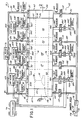
- the powder coating system 10 of this invention includes a spray booth 12 having a ceiling 14, a floor 16, opposed outer side walls 18, 20 and end walls 22, 24 formed with a booth inlet 26 and booth outlet 28, respectively.
- This construction of spray booth 12 forms an interior 30 defining a substantially controlled area in which to apply powder coating material onto objects such as a vehicle body 34 moved by a conveyor 36 through the spray booth 12.
- Oversprayed powder material which does not adhere to the vehicle body 34 passes through gratings 38 located along the floor 16 of the spray booth 12 and into a powder collection and recovery system 40, the function of which is described in more detail below.
- the interior 30 of powder spray booth 12 also includes a pair of inner side walls 42 and 44, spaced inwardly from the outer side walls 18, 20, respectively, which extend longitudinally from the end wall 24 toward the end wall 22 formed with the booth inlet 26.
- a space is formed between the end wall 22 and the leading edge of inner side walls 42, 44 which forms a cut-in zone 46 within the booth interior 30 whose cross sectional area is defined by the ceiling 14, floor 16 and the outer side walls 18, 20.
- Downstream from this cut-in zone 46, in between the inner side walls 42, 44 are a side coating zone 48 and an overhead coating zone 50, both of which are defined by the ceiling 14, floor 16 and the inner side walls 42, 44.
- the side and overhead coating zones 48, 50 thus have a smaller cross sectional area than that of cut-in zone 46.
- the spray coating operation described below includes a three-stage powder coating sequence.
- the vehicle body 34 is transported by the conveyor 36 through the booth inlet 26 into the cut-in zone 46 which has sufficient cross sectional area to permit opening of its doors as schematically depicted in Fig. 2.
- hand-held or robotically manipulated powder dispensers such as spray guns 49 apply powder coating material onto the inside surfaces of the vehicle doors, hood, engine bay, trunk and other hard to reach areas.
- the vehicle body 34 is advanced into the side coating zone 48 where powder dispensers 51 are manipulated by automatically operated dispenser moving devices (not shown) to apply powder coating material onto the vertically oriented surfaces of the vehicle body 34 such as the outside of the doors, the fenders and any other vertical surfaces.
- the vehicle body 34 is then advanced from the side coating zone 48 into the overhead coating zone 50 where powder dispensers 53 located on an overhead carrier 55 above the path of the vehicle body 34 apply powder coating material onto the horizontal surfaces of the vehicle body 34, such as the hood, roof and trunk.
- transition zones 57 and 59 The purpose of the transition zones 57 and 59 is to collect oversprayed powder which is drawn by the slight draft or wake created by the movement of the vehicle body 34 through the booth interior 30. This draft or wake can draw the powder coating material overspray from the cut-in zone 46 into the side coating zone 48, and/or from the side coating zone 48 into the overhead coating zone 50, which, unless collected within the transition zones 57, 59, could adversely effect the spraying conditions in the booth 12.
- transition zone 61 at the booth inlet 26 and another transition zone 63 at the booth outlet 28.
- the transition zone 63 at the booth outlet 28 helps prevent the draft or wake of the vehicle 34 from pulling powder coating material overspray out of the booth which could contaminate vehicle processing areas downstream from the booth or the plant in general.
- the transition zone 61 located at the inlet 26 helps prevent the introduction of thermal currents or layers to the coating zones.
- Each of the coating zones 46, 48 and 50 is provided with a dedicated system for introducing make-up air therein, and for withdrawing filtered air from the bottom of the booth 12 into the powder recovery system 40.
- the transition zones 57 and 59 are provided with one of two alternative systems for introducing make-up air therein and for withdrawing filtered air from the booth interior 30, as described below.
- the make-up air delivery and exhaust system associated with the cut-in zone 46 is described in detail herein, it being understood that the identical structure may be provided for both the side coating zone 48 and overhead coating zone 50.
- the reference numerals used to describe the structure associated with the cut-in zone 46 include the letter "A"
- the identical structure associated with the side coating zone 48 and overhead coating zone 50 include the letters "B" and "C", respectively.
- make-up air is supplied into the cut-in zone 46 by an air house 60A containing a variable speed air feed blower 62A which is connected by a feed duct 64A to an air plenum 66A mounted at the top or ceiling 14 of the spray booth 12 along the length of the cut-in zone 46.
- the plenums 66B and 66C extend along the length of the side coating zone 48 and overhead coating zone 50, respectively.
- the air house 60A introduces make-up or "conditioned" air, i.e., filtered and tempered air, through the feed duct 64A into the plenum 66A which distributes the conditioned air along the length of the cut-in zone 46.
- the feed duct 64A is provided with an air velocity sensor 68A, an adjustable damper 70A and a damper operator 72A which opens and closes the damper 70A.
- the air velocity sensor 68A and damper operator 72A of feed duct 64A are connected to a controller 74 for purposes described in detail below.
- Make-up air is also introduced into the knock-down transition zones 57, 59, 61 and 63 by an air supply system which comprises an air house 76 containing a variable speed air feed blower 78.
- the blower is connected by a feed duct 80 to the plenum 82 of transition zone 57, by a feed duct 84 to the plenum 86 of the transition zone 59, by feed duct 81 to the plenum 83 of transition zone 61 and by feed duct 85 to the plenum 87 of transition zone 63.
- These plenums 82, 86, 83 and 87 effectively distribute the make-up air along the length of the transition zones 57, 59, 61 and 63, respectively.
- the feed duct 80 is provided with an air velocity sensor 88, an adjustable damper 90 and a damper operator 92 which opens and closes the damper 90.
- the feed duct 84 is provided with an air velocity sensor 88, an adjustable damper 90 and a damper operator 92 which are identical in structure and function to those associated with feed duct 80.
- Each of the transition zones 61 and 63 at the ends of the booth 10 are similarly equipped with an air velocity sensor 88, and adjustable damper 90 and a damper operator 92 in their feed ducts 81 and 85, respectively.
- the air velocity sensor 88 and damper operator 92 within each feed duct 80, 84, 81 and 85 are connected to the controller 74 for purposes described below.
- the powder collection and recovery system 40 at the base of the spray booth 12 in the area beneath the cut-in zone 46 is connected by an exhaust duct 94A through a final filter 96A to the intake side of a variable speed air exhaust fan 98A, which is connected to the controller 74.
- the discharge side of the exhaust fan 98A is connected to a discharge duct 100A, which contains a damper 102A.
- the damper 102A may be identical to the damper 70A in air feed duct 64A, and is adjustable between open and closed positions by operation of a damper operator 104A connected to the controller 74.
- the exhaust duct 94A also contains an air velocity sensor 106A operatively connected to the controller 74.
- the side coating zone 48 and overhead coating zone 50 each have the identical exhaust elements as cut-in zone 48, except that such exhaust elements are connected to the powder collection and recovery system 40 in the area of the respective side and overhead coating zones 48, 50 as shown in Fig. 1.
- the exhaust elements associated with the side coating zone 48 which are identical to those in cut-in zone 46 are given the same reference numbers except with the addition of the letter "B", while those in the overhead coating zone 50 are identified with the addition of a letter "C".
- the transition zones 57, 59, 61 and 63 also include a dedicated air exhaust system. Specifically, the area of powder collection and recovery system 40 beneath each transition zone 57, 59, 61 and 63 is connected by exhaust ducts 108, 109, 111 and 113, respectively, through final filters 110 to the intake side of a variable speed air exhaust fan 112. The discharge side of the exhaust fan 112, in turn, is connected to a discharge duct 114 which contains a damper 116 operated by a damper operator 118. In response to a signal from the controller 74, as described below, the damper operator 118 is effective to adjust the position of damper 116 between an open and closed position as required.
- Each exhaust duct 108, 109, 111 and 113 also includes an air velocity sensor 120 which is also connected to the controller 74.
- the powder collection and recovery system 40 functions to receive air and air-entrained, oversprayed powder material from each zone within the booth interior 30, filter the oversprayed powder to form clean air and then discharge the clean air through the exhaust ducts 94A-C, and 108, to atmosphere or back to the air houses 60A-C and 76.
- the collected, oversprayed powder is transmitted from the system 40 to a hopper or other container (not shown) for storage or reuse.
- the blower 62A, air velocity sensor 68A and damper operator 72A which supply conditioned air into the cut-in zone 46 are each connected to the controller 74.
- the velocity sensor 106A, fan 98A and damper operator 104A which withdraw air from the powder collection and recovery system 40 in the area of cut-in zone 46 are also connected to the controller 74.
- These same air supply and exhaust elements associated with the side coating zone 48, overhead coating zone 50 and transition zones 57, 59 are also connected to the controller 74 as depicted schematically by the three groups of bracketed leads shown in Fig. 1.
- the controller 74 is effective to control the operation of the entire system 10 in accordance with the position of one or more vehicle bodies 34 in the booth interior 30.
- the above-described air flow system of spray booth 12 acts to control the air velocity within the booth interior 30.
- the powder coating material discharged from the dispensers 49, 51 and 53 within the booth interior 30 is relatively lightweight, having a specific gravity, for example, in the range from about 0.9 to 1.4, compared, for example, to atomized liquid paint particles, and must be applied with particular attention to the air velocity within the interior 30 of spray booth 12. It has been found that spray conditions for powder coating material vary with the type of application, i.e., side coating, top coating, cut-in, and are most favorable when the air velocity within a coating zone does not exceed a predetermined value.
- a calibration procedure is utilised to obtain air velocity measurements in each coating zone 46, 48 and 50 within the booth interior 30 based on the position therein of a vehicle body 34 of given type and dimension. Initially, all of the air feed blowers 62A-C and 78, and the air exhaust fans 98A-C and 112, are operated at a constant speed when the system 10 is first activated and no vehicle bodies 34 are present within the booth interior 30.
- a calibration procedure is then undertaken in which a vehicle body 34 is first moved into the cut-in zone 46 and the speed of operation of the air feed blower 62A and/or exhaust fan 98A is adjusted to introduce air at an "air flow rate", i.e., an air flow volume per unit time (CFM), such that the downdraft air velocity through the cut-in zone 46 of the booth interior 30 is a constant predetermined value, such as, for example, about sixty feet per minute (18.3 metres per minute).
- an air flow rate i.e., an air flow volume per unit time (CFM)
- This air flow rate is obtained by placing an air velocity measuring device or devices within the cut-in zone 46, and then varying the speed of operation of the blower 62A and/or exhaust fan 98A as the vehicle moves through the cut-in zone 46 to maintain a substantially constant downdraft velocity within the cut-in zone 46. Variation of the blower 62A and/or exhaust fan 98A speed is required because the vehicle body 34 displaces progressively more air within the cut-in zone 46 until it is entirely contained therein, and then progressively less air is displaced as the vehicle body 34 exits the cut-in zone 46.
- a sufficient number of air velocity measurements are taken within the cut-in zone 46 as the vehicle body 34 moves therethrough to obtain appropriate speed settings for the blower 62A and/or exhaust fan 98A so that the air flow rate into the cut-in zone 46 is adjusted as a function of the position of the vehicle body 34 to produce a constant downdraft velocity throughout movement of the vehicle body 34 through the cut-in zone 46.
- speed settings are recorded in the controller 74 for a particular vehicle type.
- the calibration procedure is conducted in the side coating zone 48 and overhead coating zone 50 in the same manner described above.
- sufficient measurements of downdraft velocity are taken to obtain the appropriate speed settings of the blower 62B and/or exhaust fan 98B in the side coating zone 48, and the blower 62C and/or exhaust fan 98C in the overhead coating zone 50, in order to maintain constant downdraft velocity as the vehicle body 34 moves through each zone 48, 50.
- the air velocity calibration measurements in the side coating zone 48 are taken at a location between one of the inner side walls 42 or 44 and a vertically oriented section of the vehicle body 34, e.g., a door or fender, at about the midpoint of the height of such vertical section.
- the highest air velocity within side coating zone 48 is produced within this relatively narrow area between the side walls 42, 44 and vehicle body 34, and thus it is preferable to obtain the speed settings of blower 62B and/or exhaust fan 98B using calibration measurements from this area.
- the air velocity calibration measurements for the overhead coating zone 50 are taken at one or more locations along the horizontally oriented surfaces of the vehicle body 34 such as the hood, roof and/or trunk. This ensures that the speed settings of the blower 62C and/or fan 98C associated with the overhead coating zone 48 are set to obtain an air flow rate within the overhead coating zone 50 which produces the desired, downdraft velocity along those horizontally oriented sections of the vehicle body 34 which are coated therein.
- the speed settings obtained for the blower 62B and fan 98B of the side coating zone 48, as well as those obtained for blower 62C and fan 98C of the overhead coating zone 50, are also stored in the controller 74 for a production run.
- operation of the air flow system of the spray booth 12 proceeds as follows.
- the vehicle body 34 enters into the spray booth 12 through the booth inlet 26 knock-down zone via the conveyor 36 to prevent the introduction of thermal air currents and to prevent the speed of the powder overspray material from leaving the cut-in zone 46.
- the blower 78 of the air house 76 associated with the transition zones is operated at a relatively high flow rate as schematically depicted in Fig. 2.
- the controller 74 sends signals to the feed blower 62A and/or exhaust fan 98A to provide a flow of air to the cut-in zone 46 of the booth interior 30 from the feed duct 64A and plenum 66A at a flow rate profile 122 which was obtained as a result of the above-described calibration procedure.
- the controller 74 sends signals to the feed blower 62A and/or exhaust fan 98A to provide a flow of air to the cut-in zone 46 of the booth interior 30 from the feed duct 64A and plenum 66A at a flow rate profile 122 which was obtained as a result of the above-described calibration procedure.
- the air flow rate decreases or "ramps down" at 122a as the vehicle body 34 enters cut-in zone 46, remains at a substantially constant level 122b when the entire vehicle body 34 is present therein, and then increases or "ramps up” at 122c back to the initial level as the vehicle body 34 leaves the cut-in zone 46.
- powder coating material is applied by hand-held or robotically manipulated powder dispensers 49 as described above.
- the vehicle body 34 proceeds from the cut-in zone 46 toward the side coating zone 48, but in the course of movement to the side coating zone 48 the vehicle body 34 passes through the first transition zone 57.
- the transition zone 57 is provided to collect such oversprayed powder as the vehicle body 34 passes therethrough.
- the blower 78 of air house 76 associated with the transition zones 57, 59 is operated at a relatively high flow rate 124 as depicted in Fig. 2.
- the controller 74 operates to vary the speed of operation of the blower 62B and/or exhaust fan 98B in accordance with the air velocity profile 126 obtained during the calibration procedure. Initially, as the vehicle body 34 enters the side coating zone 48, the air flow rate supplied by duct 64B to the side coating zone 48 and exhausted by duct 94B is decreased or ramped down as depicted at 126a to a lower level 126b illustrated at the center of Fig. 2.
- This lower air flow rate 126b supplied to and from the side coating zone 48 is necessary in order to maintain the air velocity therein below the predetermined maximum level with the entire vehicle body 34 present within zone 48, and may be less than the lowest air flow rate level 122b within the cut-in zone 46 because the vehicle body 34 displaces proportionately more volume within the smaller side coating zone 48 than in the larger cut-in zone 46.
- the air flow rate as depicted at 126c increases or "ramps up" back to the initial level.
- controller 74 is sequenced with the speed at which the conveyor 36 advances the vehicle body 34 through the booth interior 30 such that the speed of blowers 62A, B and/or exhaust fans 98A, B is automatically adjusted in accordance with the position of the vehicle body 34 within the cut-in zone 46 and the side coating zone 48, respectively. This ensures that the air velocity at any location in either zone 46 or 48 does not exceed the predetermined maximum level.
- the vehicle body 34 After having received a coating of powder material on its vertically oriented areas, the vehicle body 34 then proceeds from the side coating area 48 through the second transition zone 59 to the overhead coating zone 50.
- the speed of operation of blower 62B and/or fan 98B associated with side coating zone 48 increases or "ramps up" the air flow rate within such zone 48 as the vehicle body 34 leaves and enters the knock-down or transition zone 57.
- This second transition zone 59 functions in the same manner as the first transition zone 57 and is effective to collect any oversprayed powder coating material which may be drawn by the vehicle body 34 from the side coating area 48 toward the overhead coating area 50. As depicted in Fig.
- the air feed blower 78 of air house 76 associated with the transition zones 57, 59 is operated at a high level 124 compared to the blower 62A-C and/or exhaust fans 98A-C to ensure that essentially none of the oversprayed coating material is transmitted between coating zones.
- blower 62C and/or exhaust fan 98C When the vehicle body 34 enters the overhead coating zone 50, the speed of operation of blower 62C and/or exhaust fan 98C is governed by the air velocity profile 128 obtained during the calibration procedure. Initially, the air flow rate is decreased or ramped-down as depicted at 128a to obtain an an air flow rate 128b within the ducts 64C and 94C supplying and exhausting the overhead coating zone 50 which is appropriate when the entire vehicle body 34 is present therein. As the vehicle body 34 leaves the overhead coating zone 50 and proceeds to the transition zone 63 at the booth outlet 28, the speed of operation of the blower 62C and exhaust fan 98C is allowed to increase as depicted at 128c in preparation for another coating operation on the next vehicle body 34 (not shown).
- the booth outlet may include a knock-down or transition zone to help prevent the overspray material from escaping the booth and contaminating other parts of the plant.
- the blower 78 of the air house 76 associated with the transition zones is operated at a relatively high flow rate 130.
- the achievement of the top coat finish is conducted under the following conditions.
- the powder coating material is manufactured by PPG, and is commercially available under the designation ENVIRACRYL TM ; however, it is believed that other powders would be applicable for use within a coating zone.
- Such powder coating material has a small particle size, i.e., average in the range of 10-12 microns, compared to standard powders Utilizing such powder coating material, the downdraft velocity is maintained such as not to exceed 60 feet per minute (18.3 metres per minute) within the side coating zone 48:
- the downdraft velocity of the cut-in zone 46 is maintained at not less than 100 feet per minute (30.5 metres per minute) to satisfy the NFPA ventilation requirements for a manual operation.
- This downdraft velocity could change, however, in an automatic cut-in operation such as performed by robots.
- the downdraft velocity of the overhead coating zone 50 is within the range of about 120 to 140 feet per minute (36.6 to 42.7 metres per minute).
- the downdraft velocity within the coating zones 46, 48 and 50 of the booth interior 30 can be sufficiently controlled by varying the speed of operation of the feed blowers 62A-C individually, or in combination with the speed of operation of exhaust fans 98A-C.
- some additional flow adjustment may be required. That is, the range of the frequency of operation of the feed blowers 62A-C and/or exhaust fans 98A-C may not be sufficient to increase or decrease the air flow within one or more of the coating zones 46, 48 and/or 50 to the degree required to properly adjust the air velocity therein.
- the controller 74 is effective to partially open or close the damper 70A-C in feed ducts 64A-C, respectively, and/or the damper 102A-C in the discharge ducts 100A-C, respectively, so as to obtain the required air flow into or out of one or more of the coating zones 46, 48 and/or 50.
- the dampers 70A-C and/or 102A-C can be manually adjusted to the desired position in lieu of automatic adjustment. In this manner, the appropriate air velocity can be obtained regardless of the size of the vehicle body 34.
- Each feed duct 64A-C may be provided with a pressure sensor (not shown). This may be accomplished with an individual pressure sensor or with a sensor 68A-C which measures both the flow rate and the pressure. The sensor would only be required in the calibration procedure to assure that the blower motors 62A-C were operating within the appropriate fan curves.
- a slightly negative pressure may be maintained within the interior 30 of spray booth 12 for the purpose of preventing any powder from exiting the booth interior 30 through the booth inlet 26 or outlet 28.
- Maintenance of a slightly negative pressure within the booth interior 30 can be achieved by ensuring that the flow rate of air directed into the spray booth 12 from the air houses 60A-C and 76 is always slightly less than the flow of filtered air withdrawn from the booth interior 30 through the exhaust ducts 94A-C and 108.
- the air velocity sensors 68A-C and 88 each may be a multi-point sensing device which measures the air velocity at a number of different points and averages them to produce a signal corresponding to the average air velocity.
- the signals are sent to the controller 74 which calculates the flow rate of the air from the respective air houses 60A-C and 76 by multiplying the sensed air velocity times the cross sectional area of the respective feed ducts 64A-C, 80 and 84.
- the flow rate of the conditioned air entering the booth interior 30 through the feed ducts 64A-C, 80 and 84 is compared in the controller 74 with the flow rate of the filtered air withdrawn from the booth interior 30 through the exhaust ducts 94A-C, 108, 109 respectively.
- the controller 74 is effective to maintain a predetermined difference between the flow rate in the feed ducts 64A-C, 80 and 84, and exhaust ducts 94A-C, 108 and 109, by adjusting the speed of operation of the variable speed, feed blowers 62A-C and 78 in the air houses 60A-C and 76, respectively, and/or by adjusting the speed of operation of the variable speed exhaust fans 98A-C and 112 connected to the exhaust ducts 94A-C, 108 and 109, respectively. This ensures that a slightly negative pressure is maintained within the booth interior 30 throughout operation of the spray booth 12.
- the controller 74 may therefore fulfil two separate purposes. As mentioned above, one function of the controller 74 is to automatically “ramp down” and then “ramp up” the speed of blowers 62A-C and 78, and/or exhaust fans 98A-C and 112, in accordance with the position of the vehicle body 34 within spray booth 12. At the same time, the controller 74 functions to adjust the operational speed of the blowers 62A-C and 78, and/or exhaust fans 98A-C and 112, to ensure a slightly negative pressure is maintained within the booth interior 30.
- the controller 74 may include one closed loop which controls operational speed of the blowers 62A-C and 78, and/or exhaust fans 98A-C and 112, to perform the "ramp up-ramp down" function, and a second closed loop which maintains negative pressure within the booth interior 30.
- the "ramp up-ramp down” function involves a "macro" or relatively large magnitude of adjustment of the operational speed of the blowers 62A-C and 78, and/or exhaust fans 98A-C and 112, whereas an adjustment to maintain the negative pressure within the booth interior generally requires a relatively small or "micro" adjustment.
- adjustment of the blowers 62A-C and 78, and/or exhaust fans 98A-C and 112, to maintain negative pressure within the booth 12 is accomplished dynamically, i.e., the air velocity sensors 68A-C and 88 in feed ducts 64A-C, 80 and 84, respectively, and sensors 106A-C and 120 in exhaust ducts 94A-C, 108 and 109, respectively, operate to sense the air flow rate throughout the system operation, including the "ramp up-ramp down" period, and send signals to the second closed loop in the controller 74 to obtain the appropriate "micro or small magnitude adjustment.
- a controller 74 such as an Allen Bradley PLC5 or other suitable commercially available, closed loop controllers, P.C.s or microprocessors can be employed in the system herein.
- blowers 62A-c and/or exhaust fans 98A-C may be required to maintain the negative pressure with a zone of the booth.
- the introduction of air introduced into a coating zone by the spray guns 51 and/or 53 may be sufficient to affect the negative pressure within a zone and/or affect the air flow therein. Therefore, in some instances it may be necessary to adjust the speed of a blower 62A-C and/or the associated exhaust fan 98A-C of a zone in conjunction with the operation of the spray guns.
- the exhaust fan speed could be increased in conjunction with the operation of several spray guns of a zone to maintain the negative pressure of the zone and/or booth.
- a single air house 76 and air feed blower 78 is employed to provide conditioned air to a feed duct 80 connected to the plenum 82 of first transition zone 57 and to the feed duct 84 connected to the plenum 86 of second transition zone 59.
- a separate air house and air feed blower could be employed for each knock-down or transition zone 57 and 59 in order to individually control the flow of conditioned air into such zones 57 and 59, if desired.
- This same type of arrangement is employed on the exhaust side of transition zones 57, 59 wherein the exhaust ducts 108, 109 for the respective zones 57, 59 are connected to a single exhaust fan 112.
- Each duct 108, 109 could also be provided with a separate exhaust fan 112, if desired.
- controller 74 is described as being sequenced with the speed of the conveyor which transports the vehicle body 34 through the booth 12.
- position sensors could be provided within the interior 30 of booth 12 to sense the position of a vehicle body 34 within any of the zones 46, 48 or 50 therein and send appropriate signals to drive the controller 74 in accordance with the sensed vehicle position.
- the booth interior 30 could be formed with the same cross sectional area along its entire length.
Landscapes
- Application Of Or Painting With Fluid Materials (AREA)
- Details Or Accessories Of Spraying Plant Or Apparatus (AREA)
- Paints Or Removers (AREA)
- Coating Apparatus (AREA)
Applications Claiming Priority (2)
| Application Number | Priority Date | Filing Date | Title |
|---|---|---|---|
| US594105 | 1990-10-09 | ||
| US07/594,105 US5095811A (en) | 1990-10-09 | 1990-10-09 | Automotive powder coating booth with modulated air flow |
Publications (3)
| Publication Number | Publication Date |
|---|---|
| EP0480664A2 true EP0480664A2 (de) | 1992-04-15 |
| EP0480664A3 EP0480664A3 (en) | 1992-06-03 |
| EP0480664B1 EP0480664B1 (de) | 1995-12-27 |
Family
ID=24377541
Family Applications (1)
| Application Number | Title | Priority Date | Filing Date |
|---|---|---|---|
| EP91309191A Expired - Lifetime EP0480664B1 (de) | 1990-10-09 | 1991-10-08 | Verbesserungen für Pulverbeschichtungskabinen mit geregelter Lüftung zur Beschichtung von Kraftfahrzeugen |
Country Status (9)
| Country | Link |
|---|---|
| US (1) | US5095811A (de) |
| EP (1) | EP0480664B1 (de) |
| JP (1) | JPH04260464A (de) |
| KR (1) | KR920007699A (de) |
| AT (1) | ATE132061T1 (de) |
| AU (1) | AU631515B2 (de) |
| CA (1) | CA2051563A1 (de) |
| DE (1) | DE69115831T2 (de) |
| MX (1) | MX9101492A (de) |
Cited By (11)
| Publication number | Priority date | Publication date | Assignee | Title |
|---|---|---|---|---|
| EP0584638A3 (en) * | 1992-08-28 | 1994-07-20 | Alfred Feige | Ventilation device for spraying booths or similar |
| WO1995031292A1 (de) * | 1994-05-17 | 1995-11-23 | ABB Fläkt AB | Bearbeitungskabine und verfahren zum belüften einer bearbeitungskabine |
| GB2296205A (en) * | 1994-12-19 | 1996-06-26 | Ford Motor Co | Paint spray booth air speed control |
| WO1998028088A3 (de) * | 1996-12-20 | 1998-10-15 | Waelti Ag Geb | Spritzkabine und luftzirkulationssystem für einen arbeitsraum |
| GB2341444A (en) * | 1998-09-08 | 2000-03-15 | Ford Global Tech Inc | Paint booth airflow control system |
| EP0974400A3 (de) * | 1993-05-25 | 2000-04-26 | Nordson Corporation | Pulverbeschichtungssystem |
| US6361605B1 (en) | 1993-05-25 | 2002-03-26 | Nordson Corporation | Vehicle powder coating system |
| EP1493495A2 (de) | 2003-07-02 | 2005-01-05 | Technoplants S.r.l. | Sprühkabine |
| EP2368642A1 (de) * | 2010-01-19 | 2011-09-28 | Thomas Dipl.-Ing. Pilz | Belüftungsvorrichtung für Spritzlackieranlagen |
| WO2015007865A1 (de) * | 2013-07-18 | 2015-01-22 | Fraunhofer-Gesellschaft zur Förderung der angewandten Forschung e. V. | Belüftungssystem für ein gebäude |
| EP2581138A3 (de) * | 2011-10-11 | 2017-01-25 | H. Börger & Co. GmbH | Pulverbeschichtungsanlage mit Sprühmitteln und gegenüberliegenden Absaugöffnungen |
Families Citing this family (41)
| Publication number | Priority date | Publication date | Assignee | Title |
|---|---|---|---|---|
| JP3038052B2 (ja) * | 1991-07-05 | 2000-05-08 | 株式会社大氣社 | 気圧勾配制御装置 |
| US5205783A (en) * | 1991-08-22 | 1993-04-27 | Accu*Aire Systems, Inc. | Air flow control equipment in chemical laboratory buildings |
| US5356334A (en) * | 1992-10-01 | 1994-10-18 | Binks Manufacturing Company | Apparatus and method for airborne particulate booth |
| US5326599A (en) * | 1993-02-11 | 1994-07-05 | Nordson Corporation | Cabin purge system for automotive powder coating |
| JPH06246206A (ja) * | 1993-02-17 | 1994-09-06 | Nordson Corp | 複数のフィルターモジュールを備えた粉体スプレーブース |
| US5443642A (en) * | 1993-10-22 | 1995-08-22 | Wagner Systems Inc. | Apparatus for electrostatic spray painting |
| US5505763A (en) * | 1994-10-07 | 1996-04-09 | Nordson Corporation | System and method for controlling air flow through a powder coating booth |
| KR100461985B1 (ko) * | 1996-05-30 | 2005-07-29 | 이노떼라 토픽 엥떼르나씨오날 에스.아. | 스타킹 또는 타이츠의 압박지지용구 |
| US5664995A (en) * | 1996-06-21 | 1997-09-09 | O.K. Filters Company, Inc. | Environmental enclosure apparatus with air flow control and balancing |
| WO1998000676A1 (en) * | 1996-06-28 | 1998-01-08 | Intelligent Enclosures Corporation | Environmentally enhanced enclosure for managing cmp contamination |
| US5820456A (en) | 1996-10-24 | 1998-10-13 | Sandy J. Pangle | Paint spray booth |
| US5922130A (en) * | 1997-03-31 | 1999-07-13 | Sermatech International, Inc. | Spray booth for applying coatings to substrate |
| DE19726349A1 (de) * | 1997-06-21 | 1999-01-28 | Eisenmann Foerdertech | Verfahren und Vorrichtung zum Aufbringen von Lackbeschichtungen auf Fahrzeugkarosserien |
| US6226568B1 (en) * | 1998-12-07 | 2001-05-01 | Ernest Henry Tong | Method of balancing paint booth air flows |
| US6221160B1 (en) * | 1999-02-03 | 2001-04-24 | Taiwan Semiconductor Manufacturing Co., Ltd | Method and apparatus for environmental control in a process chamber |
| CA2341802A1 (en) | 2001-03-22 | 2002-09-22 | Long Manufacturing Ltd. | Closed capture emission system |
| NL1017818C2 (nl) * | 2001-04-10 | 2002-10-15 | Cfs Bakel Bv | Luchteenheid voor het verwijderen van deeltjesvormig materiaal. |
| US6644092B1 (en) | 2001-05-14 | 2003-11-11 | Robert J. Oppel | Automatic calibration of pressure sensors for paint booth airflow control |
| US6723145B2 (en) * | 2002-01-02 | 2004-04-20 | Dürr Industries, Inc. | Open powder booth collection design |
| MXPA05008084A (es) * | 2003-01-06 | 2006-03-17 | Global Finishing Solutions Llc | Cabina de pintado de aeronave. |
| US7597534B2 (en) * | 2003-03-20 | 2009-10-06 | Huntair, Inc. | Fan array fan section in air-handling systems |
| US11255332B2 (en) | 2003-03-20 | 2022-02-22 | Nortek Air Solutions, Llc | Modular fan housing with multiple modular units having sound attenuation for a fan array for an air-handling system |
| US7137775B2 (en) | 2003-03-20 | 2006-11-21 | Huntair Inc. | Fan array fan section in air-handling systems |
| US7658017B1 (en) * | 2004-01-12 | 2010-02-09 | Thomas Brian Laviolette | Vacuum drying method |
| WO2005107923A1 (en) * | 2004-04-23 | 2005-11-17 | James Wilson Motter | Constant process exhaust system |
| US20070190474A1 (en) * | 2006-02-01 | 2007-08-16 | Su Chao A | Systems and methods of controlling systems |
| US7666077B1 (en) | 2007-11-13 | 2010-02-23 | Global Finishing Solutions, L.L.C. | Paint booth arrangement and method for directing airflow |
| US20100061865A1 (en) * | 2008-09-10 | 2010-03-11 | Lucent Technologies, Inc. | System and/or method for monitoring and/or controlling the relative internal air pressure of a facility |
| DE102008061379A1 (de) | 2008-12-10 | 2010-06-17 | Daimler Ag | Verfahren zur Abluftwärmerückgewinnung |
| US20100272915A1 (en) * | 2009-04-28 | 2010-10-28 | Seth Anthony Laws | Portable spray booth with air handling system |
| JP5401206B2 (ja) * | 2009-08-10 | 2014-01-29 | 株式会社不二製作所 | ブラスト室 |
| JP5591551B2 (ja) * | 2010-02-02 | 2014-09-17 | 日本パーカライジング株式会社 | 粉体塗装装置 |
| ITMO20100263A1 (it) * | 2010-09-21 | 2012-03-22 | Vincenzo Rina | Apparecchiatura per la verniciatura di scafi di imbarcazioni navali o simili |
| US9581347B2 (en) * | 2011-02-16 | 2017-02-28 | John L. Fiorita, JR. | Clean room control system and method |
| DE102011122056A1 (de) * | 2011-12-22 | 2013-06-27 | Eisenmann Ag | Anlage zum Beschichten von Gegenständen |
| HUE050529T2 (hu) * | 2015-05-22 | 2020-12-28 | Duerr Systems Ag | Felületbevonó berendezés és hozzá kapcsolódó mûködési eljárás |
| CN105170387B (zh) * | 2015-09-25 | 2017-08-22 | 佛山信家家具有限公司 | 一种多线程循环家具喷漆生产线 |
| JP6830169B1 (ja) * | 2020-02-10 | 2021-02-17 | 株式会社大気社 | 風量調整方法 |
| IT202100000809A1 (it) * | 2021-01-18 | 2022-07-18 | Bywell S R L | Cabina di verniciatura |
| IT202100000806A1 (it) * | 2021-01-18 | 2022-07-18 | Bywell S R L | Cabina di verniciatura |
| IT202100000815A1 (it) * | 2021-01-18 | 2022-07-18 | Bywell S R L | Cabina di verniciatura |
Family Cites Families (10)
| Publication number | Priority date | Publication date | Assignee | Title |
|---|---|---|---|---|
| DE2932392C2 (de) * | 1979-08-09 | 1988-07-28 | Aktiebolaget Svenska Fläktfabriken, 13134 Nacka | Spritzkabine |
| FR2465961A2 (fr) * | 1979-09-26 | 1981-03-27 | Omia | Dispositif de reglage de debit d'air, notamment pour cabines de peinture |
| DE3006837C2 (de) * | 1980-02-23 | 1983-02-17 | Basf Farben + Fasern Ag, 2000 Hamburg | Verfahren und Vorrichtung zum elektrostatischen Beschichten von Großwerkstücken mit pulverförmigen Medien |
| JPS624464A (ja) * | 1985-07-02 | 1987-01-10 | Honda Motor Co Ltd | 車体塗装装置 |
| JPS62152567A (ja) * | 1985-12-27 | 1987-07-07 | Trinity Ind Corp | 給気付塗装ブ−スの運転方法 |
| JPS62152569A (ja) * | 1985-12-27 | 1987-07-07 | Trinity Ind Corp | 給気付塗装ブ−スの運転方法 |
| US4730553A (en) * | 1985-12-27 | 1988-03-15 | Trinity Industrial Corporation | Method of operating an air-supplied type coating booth |
| SE455674B (sv) * | 1986-10-22 | 1988-08-01 | Lindema Kb | Vertikal sallanordning |
| JPS63171663A (ja) * | 1987-01-10 | 1988-07-15 | Toyota Motor Corp | 塗装ブ−ス |
| JPH026868A (ja) * | 1988-06-25 | 1990-01-11 | Taikisha Ltd | 塗装ブースにおける塗装装置設置方法と塗装ブースの一部を構成する塗装機操作ユニット |
-
1990
- 1990-10-09 US US07/594,105 patent/US5095811A/en not_active Expired - Fee Related
-
1991
- 1991-09-17 CA CA002051563A patent/CA2051563A1/en not_active Abandoned
- 1991-10-08 EP EP91309191A patent/EP0480664B1/de not_active Expired - Lifetime
- 1991-10-08 AU AU85685/91A patent/AU631515B2/en not_active Ceased
- 1991-10-08 KR KR1019910017569A patent/KR920007699A/ko not_active Withdrawn
- 1991-10-08 AT AT91309191T patent/ATE132061T1/de not_active IP Right Cessation
- 1991-10-08 DE DE69115831T patent/DE69115831T2/de not_active Expired - Fee Related
- 1991-10-09 MX MX9101492A patent/MX9101492A/es unknown
- 1991-10-09 JP JP3260935A patent/JPH04260464A/ja not_active Withdrawn
Cited By (20)
| Publication number | Priority date | Publication date | Assignee | Title |
|---|---|---|---|---|
| EP0584638A3 (en) * | 1992-08-28 | 1994-07-20 | Alfred Feige | Ventilation device for spraying booths or similar |
| US7247205B2 (en) | 1993-05-25 | 2007-07-24 | Nordson Corporation | Vehicle powder coating system |
| US6929698B2 (en) | 1993-05-25 | 2005-08-16 | Nordson Corporation | Vehicle powder coating system |
| US6361605B1 (en) | 1993-05-25 | 2002-03-26 | Nordson Corporation | Vehicle powder coating system |
| EP0974400A3 (de) * | 1993-05-25 | 2000-04-26 | Nordson Corporation | Pulverbeschichtungssystem |
| US7166164B2 (en) | 1993-05-25 | 2007-01-23 | Nordson Corporation | Vehicle powder coating system |
| WO1995031292A1 (de) * | 1994-05-17 | 1995-11-23 | ABB Fläkt AB | Bearbeitungskabine und verfahren zum belüften einer bearbeitungskabine |
| US5762548A (en) * | 1994-05-17 | 1998-06-09 | Abb Flakt Ab | Treatment cubicle and a method of ventilating a treatment cubicle |
| GB2296205B (en) * | 1994-12-19 | 1998-04-22 | Ford Motor Co | Paint spray booth air speed control |
| GB2296205A (en) * | 1994-12-19 | 1996-06-26 | Ford Motor Co | Paint spray booth air speed control |
| WO1998028088A3 (de) * | 1996-12-20 | 1998-10-15 | Waelti Ag Geb | Spritzkabine und luftzirkulationssystem für einen arbeitsraum |
| US6264547B1 (en) | 1996-12-20 | 2001-07-24 | WäLTI ROBERT | Spraying booth and circulation system for a working chamber |
| GB2341444A (en) * | 1998-09-08 | 2000-03-15 | Ford Global Tech Inc | Paint booth airflow control system |
| GB2341444B (en) * | 1998-09-08 | 2003-02-26 | Ford Global Tech Inc | Paint booth airflow control system |
| US6146264A (en) * | 1998-09-08 | 2000-11-14 | Ford Global Technologies, Inc. | Paint booth airflow control system |
| EP1493495A2 (de) | 2003-07-02 | 2005-01-05 | Technoplants S.r.l. | Sprühkabine |
| EP1493495A3 (de) * | 2003-07-02 | 2007-10-31 | Technoplants S.r.l. | Sprühkabine |
| EP2368642A1 (de) * | 2010-01-19 | 2011-09-28 | Thomas Dipl.-Ing. Pilz | Belüftungsvorrichtung für Spritzlackieranlagen |
| EP2581138A3 (de) * | 2011-10-11 | 2017-01-25 | H. Börger & Co. GmbH | Pulverbeschichtungsanlage mit Sprühmitteln und gegenüberliegenden Absaugöffnungen |
| WO2015007865A1 (de) * | 2013-07-18 | 2015-01-22 | Fraunhofer-Gesellschaft zur Förderung der angewandten Forschung e. V. | Belüftungssystem für ein gebäude |
Also Published As
| Publication number | Publication date |
|---|---|
| JPH04260464A (ja) | 1992-09-16 |
| EP0480664A3 (en) | 1992-06-03 |
| MX9101492A (es) | 1992-06-05 |
| AU631515B2 (en) | 1992-11-26 |
| DE69115831T2 (de) | 1996-05-23 |
| KR920007699A (ko) | 1992-05-27 |
| CA2051563A1 (en) | 1992-04-10 |
| EP0480664B1 (de) | 1995-12-27 |
| AU8568591A (en) | 1992-04-16 |
| ATE132061T1 (de) | 1996-01-15 |
| US5095811A (en) | 1992-03-17 |
| DE69115831D1 (de) | 1996-02-08 |
Similar Documents
| Publication | Publication Date | Title |
|---|---|---|
| EP0480664B1 (de) | Verbesserungen für Pulverbeschichtungskabinen mit geregelter Lüftung zur Beschichtung von Kraftfahrzeugen | |
| US5397394A (en) | Powder coating booth | |
| EP0974400B1 (de) | Pulverbeschichtungssystem | |
| CA2813097C (en) | Process chamber with device for injecting gaseous fluid | |
| AU678216B2 (en) | Flat line powder coating system | |
| US4662309A (en) | Portable powder spray booth | |
| CN102665931B (zh) | 用于物体的表面处理的设备 | |
| JPH05505976A (ja) | 粉体被覆システム | |
| US6620243B1 (en) | Fluidized bed powder handling and coating apparatus and methods | |
| RU2622125C2 (ru) | Устройство для сбора аэрозоля покрытия | |
| JP2000167453A (ja) | 塗装ブ―スの空気流の平衡化方法 | |
| HUP0001635A2 (hu) | Porlasztó festőfülke és cirkulációs rendszer munkatérhez | |
| CN110681521A (zh) | 用于处理工件的处理设备和方法 | |
| JP2001502239A (ja) | 塗料スプレーブース | |
| JP7500581B2 (ja) | 車両本体を表面処理するための表面処理設備及び表面処理方法 | |
| JPH10507129A (ja) | 粉体コーティング・ブースを介して空気流を制御するシステムおよび方法 | |
| CN101272868A (zh) | 用于分离喷涂湿漆的装置和方法 | |
| KR20120016142A (ko) | 작업편을 코팅하기 위한 방법과 코팅 설비 | |
| US7001262B2 (en) | System for dynamic airflow control in a paint booth using multiple air supply plenums | |
| RU2145526C1 (ru) | Обрабатывающая секция и способ вентилирования обрабатывающей секции | |
| JPH11253855A (ja) | 自動車用塗装ブース | |
| JP2000093860A (ja) | 塗装ブース | |
| JP3708445B2 (ja) | 粉体塗装材料供給装置 | |
| JPS646934Y2 (de) | ||
| JPS60861A (ja) | 多コ−ト1ベ−ク型塗料の塗装方法およびその塗装々置 |
Legal Events
| Date | Code | Title | Description |
|---|---|---|---|
| PUAI | Public reference made under article 153(3) epc to a published international application that has entered the european phase |
Free format text: ORIGINAL CODE: 0009012 |
|
| AK | Designated contracting states |
Kind code of ref document: A2 Designated state(s): AT BE CH DE DK ES FR GB LI NL SE |
|
| PUAL | Search report despatched |
Free format text: ORIGINAL CODE: 0009013 |
|
| AK | Designated contracting states |
Kind code of ref document: A3 Designated state(s): AT BE CH DE DK ES FR GB LI NL SE |
|
| 17P | Request for examination filed |
Effective date: 19921130 |
|
| 17Q | First examination report despatched |
Effective date: 19940318 |
|
| GRAA | (expected) grant |
Free format text: ORIGINAL CODE: 0009210 |
|
| AK | Designated contracting states |
Kind code of ref document: B1 Designated state(s): AT BE CH DE DK ES FR GB LI NL SE |
|
| PG25 | Lapsed in a contracting state [announced via postgrant information from national office to epo] |
Ref country code: NL Free format text: LAPSE BECAUSE OF FAILURE TO SUBMIT A TRANSLATION OF THE DESCRIPTION OR TO PAY THE FEE WITHIN THE PRESCRIBED TIME-LIMIT Effective date: 19951227 Ref country code: LI Effective date: 19951227 Ref country code: ES Free format text: THE PATENT HAS BEEN ANNULLED BY A DECISION OF A NATIONAL AUTHORITY Effective date: 19951227 Ref country code: DK Effective date: 19951227 Ref country code: CH Effective date: 19951227 Ref country code: BE Effective date: 19951227 Ref country code: AT Effective date: 19951227 |
|
| REF | Corresponds to: |
Ref document number: 132061 Country of ref document: AT Date of ref document: 19960115 Kind code of ref document: T |
|
| REF | Corresponds to: |
Ref document number: 69115831 Country of ref document: DE Date of ref document: 19960208 |
|
| ET | Fr: translation filed | ||
| NLV1 | Nl: lapsed or annulled due to failure to fulfill the requirements of art. 29p and 29m of the patents act | ||
| PG25 | Lapsed in a contracting state [announced via postgrant information from national office to epo] |
Ref country code: SE Effective date: 19961009 |
|
| PLBE | No opposition filed within time limit |
Free format text: ORIGINAL CODE: 0009261 |
|
| STAA | Information on the status of an ep patent application or granted ep patent |
Free format text: STATUS: NO OPPOSITION FILED WITHIN TIME LIMIT |
|
| 26N | No opposition filed | ||
| EUG | Se: european patent has lapsed |
Ref document number: 91309191.4 |
|
| PGFP | Annual fee paid to national office [announced via postgrant information from national office to epo] |
Ref country code: FR Payment date: 19970910 Year of fee payment: 7 |
|
| PGFP | Annual fee paid to national office [announced via postgrant information from national office to epo] |
Ref country code: GB Payment date: 19970918 Year of fee payment: 7 |
|
| PGFP | Annual fee paid to national office [announced via postgrant information from national office to epo] |
Ref country code: DE Payment date: 19970922 Year of fee payment: 7 |
|
| PG25 | Lapsed in a contracting state [announced via postgrant information from national office to epo] |
Ref country code: GB Free format text: LAPSE BECAUSE OF NON-PAYMENT OF DUE FEES Effective date: 19981008 |
|
| GBPC | Gb: european patent ceased through non-payment of renewal fee |
Effective date: 19981008 |
|
| PG25 | Lapsed in a contracting state [announced via postgrant information from national office to epo] |
Ref country code: FR Free format text: LAPSE BECAUSE OF NON-PAYMENT OF DUE FEES Effective date: 19990630 |
|
| REG | Reference to a national code |
Ref country code: FR Ref legal event code: ST |
|
| PG25 | Lapsed in a contracting state [announced via postgrant information from national office to epo] |
Ref country code: DE Free format text: LAPSE BECAUSE OF NON-PAYMENT OF DUE FEES Effective date: 19990803 |