EP0480767B1 - Outil pour jonctions simultanées et verticales - Google Patents
Outil pour jonctions simultanées et verticales Download PDFInfo
- Publication number
- EP0480767B1 EP0480767B1 EP91309404A EP91309404A EP0480767B1 EP 0480767 B1 EP0480767 B1 EP 0480767B1 EP 91309404 A EP91309404 A EP 91309404A EP 91309404 A EP91309404 A EP 91309404A EP 0480767 B1 EP0480767 B1 EP 0480767B1
- Authority
- EP
- European Patent Office
- Prior art keywords
- connector
- tool according
- vertical
- lines
- movement
- Prior art date
- Legal status (The legal status is an assumption and is not a legal conclusion. Google has not performed a legal analysis and makes no representation as to the accuracy of the status listed.)
- Expired - Lifetime
Links
- 239000012530 fluid Substances 0.000 claims description 5
- 238000004519 manufacturing process Methods 0.000 claims description 4
- 230000008878 coupling Effects 0.000 claims description 3
- 238000010168 coupling process Methods 0.000 claims description 3
- 238000005859 coupling reaction Methods 0.000 claims description 3
- 230000004308 accommodation Effects 0.000 claims description 2
- 230000004044 response Effects 0.000 claims description 2
- 238000002347 injection Methods 0.000 claims 1
- 239000007924 injection Substances 0.000 claims 1
- 238000012544 monitoring process Methods 0.000 claims 1
- XLYOFNOQVPJJNP-UHFFFAOYSA-N water Substances O XLYOFNOQVPJJNP-UHFFFAOYSA-N 0.000 claims 1
- 238000009434 installation Methods 0.000 description 6
- 238000012423 maintenance Methods 0.000 description 5
- 230000008901 benefit Effects 0.000 description 4
- 230000007246 mechanism Effects 0.000 description 3
- 238000007789 sealing Methods 0.000 description 2
- 230000009471 action Effects 0.000 description 1
- 230000006872 improvement Effects 0.000 description 1
- 230000009467 reduction Effects 0.000 description 1
- 238000009877 rendering Methods 0.000 description 1
- 239000003643 water by type Substances 0.000 description 1
Images



Classifications
-
- F—MECHANICAL ENGINEERING; LIGHTING; HEATING; WEAPONS; BLASTING
- F16—ENGINEERING ELEMENTS AND UNITS; GENERAL MEASURES FOR PRODUCING AND MAINTAINING EFFECTIVE FUNCTIONING OF MACHINES OR INSTALLATIONS; THERMAL INSULATION IN GENERAL
- F16L—PIPES; JOINTS OR FITTINGS FOR PIPES; SUPPORTS FOR PIPES, CABLES OR PROTECTIVE TUBING; MEANS FOR THERMAL INSULATION IN GENERAL
- F16L37/00—Couplings of the quick-acting type
- F16L37/002—Couplings of the quick-acting type which can be controlled at a distance
Definitions
- This invention refers to a universal tool for simultaneous vertical connections, the main purpose of which is to locate in one single instrument, which can be easily handled and operated and is capable of maintenance, the whole active system which includes appropriate mechanisms for correctly positioning a connector bridge on two flow line terminals pertaining to equipment units to be connected.
- DE-A-3802166 discloses a manipulating device for transporting and positioning articles and comprising a rotatable column with at least one arm which extends radially and is extensible and contractable longitudinally. The ends of the arms are provided with gripping devices for holding articles. The pivot for each of the radial arms is adjustable longitudinally (vertically) of the column.
- this invention provides a tool for use in establishing simultaneous vertical connections in a system which introduces a concept of subsea remote connection between two terminal mandrels of flow lines which, being located in different structures or equipment units, present deviations due to for example manufacturing, erection, or installation tolerances. It is necessary for the tool which performs this connection, to be provided with systems which render it compatible with those deviations.
- the connection between the flow line terminals is carried out by way of a module (bridge) containing two hydraulic connectors united by a bridge of flexible or articulated lines which absorb the movements which may become necessary to accommodate the deviations in question.
- the tool makes it possible to fit the connector module, and it is also possible for the module to be recovered for eventual maintenance, thus rendering all the active elements of the system recoverable to allow for greater flexibility in the use of the equipment and a rather significant simplification concerning the problem of tolerances.
- Another advantage is the transfer, to the tool for installation of the intervention connectors, of the whole active system required for the compensation of the deviations, thereby avoiding the use of very strict manufacturing and erection tolerances of the equipment units which directly or indirectly affect the final positioning of the flow line terminals, since the whole system required for the correction of misalignments is located in the tool and is capable of being maintained and adjusted.
- Another advantage is the simplification of the operation of the more complex equipment units and the reduction of the possibility of failure of these equipment units during operation, since they no longer have the active connection of the system. Instead the possibility of failure in the connection is transferred from the complex equipment units to the connector bridge, thereby reducing the possibility of failure in the installation and enabling the maintenance of those equipment units, since those equipment units will have a smaller number of seals, and a smaller number of simultaneous connections, because the connections are distributed in connector bridges (one per well), and there are, in addition, no longer any flexible or articulated lines in those equipment units. The handling of those equipment units is as far as possible avoided since it is sometimes becoming complex and time-consuming.
- Still another advantage is the standardization of one single tool to make connections between terminals containing any arrangement of flow lines, said standardization allowing the tool to be utilized with any arrangement of flow lines pertaining to any equipment units which are to be connected.
- this invention provides a universal tool for simultaneous vertical connections as defined by claim 1.
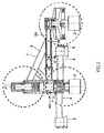
- the universal tool 1 for simultaneous vertical connections can be utilized for the installation of a connector bridge 41 containing a jumper of flexible lines (flow lines, hydraulic umbilical line, and/or electric cable; in any desired arrangement). These lines achieve the connection between two flow line terminals 64, 65.
- the tool 1 includes:
- the tool 1 of this invention thus correctly positions a connector bridge 41 on two flow line terminals 65, 65 pertaining to equipment units to be connected. Firstly the first connector 66 of the bridge is connected on the first flow line terminal 64, where the correct positioning and the necessary load are achieved through the movement of the operating column 61 (Fig. 3); during this movement the second connector 67 of the bridge is out of position.
- upward movement of the structure 6 is achieved by the application of fluid pressure in the upper chamber 28, and the downward movement is achieved through the application of pressure in the lower chamber 29.
- the movement of the structure 6 is achieved by means of the components 9, 10, 11 which are the moving components driven by means of the fluid pressure while the central component 8 forms the rigid stator element of the system so that the components 9, 10, 11 may move relative to it.
- the sealing required for the action of the hydraulic pressure in the chambers 28, 29 is achieved by means of dynamic sealing rings 12, 13.
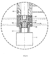
- the central component 8 presents at its upper end (Fig. 3) a female thread 60 compatible with a male thread of the operating column 61, and presents at its lower end (Fig. 4) a male thread 62 for coupling to a body 68 which is supported in a set of bearings 54, 55, 56 which allow rotation of the structure 6 which positions the second connector 3 when the operating column 61 is rotated.
- a body 57 allows the set of bearings to be independent of the first connector 2 which remains locked and fixed during the rotation of the structure 6 with the second connector 3.
- the rotation is transmitted to the structure 6 by means of the slot keys 46, 49, the slot key 46 working in a vertical slot 45 (Fig. 3) in the sleeve 47 so as to allow for the movement of the vertical compensation system.
- extension or retraction causes the shaft 20 to move horizontally, carrying with it the second connector 3.
- the articulation 24 works, in response to accommodation of movements between the second connector 67 of the connector bridge 41 and the second flow line terminal 65, by sliding in the spherical-shaped housings 25, 26.
- said orientation is utilized for the correct positioning of the first connector 66 of the bridge during system installation operation and orientation of the first connector 2 during re-installation of the tool 1 for removal of the connector bridge 41.
- the attachment of the guide arm 4 to the first connector 2 is achieved by means of a slot key 70.
- the tool 1 for simultaneous vertical connections can be utilized for connection between any flow line arrangements, and therefore has a hydraulic telescopic system (Fig. 2) which provides the connector bridge with the necessary spacing of the lines to be connected.
Landscapes
- Engineering & Computer Science (AREA)
- General Engineering & Computer Science (AREA)
- Mechanical Engineering (AREA)
- Manipulator (AREA)
- Earth Drilling (AREA)
- Soil Working Implements (AREA)
Claims (12)
- Outil pour connexions verticales simultanées susceptible d'être utilisé dans l'installation d'un pont de connexion (41) comprenant un cavalier de liaison de conduites flexibles qui assure la connexion entre deux terminaux de conduites d'écoulement (64, 65), comprenant des connecteurs hydrauliques verticaux (2, 3) pour bloquer sur des mandrins d'éclissage (50, 51) du pont de connexion (41), lesdits connecteurs verticaux (2, 3) comprenant des bras de support (68, 27), un système de compensation verticale avec un mouvement ascendant et descendant d'une structure (6) qui supporte le puits du deuxième connecteur (3), un système à rotation pour faire tourner la structure (6) via un jeu de paliers (54, 55, 56) situés dans la partie inférieure d'un boîtier (7) du système de compensation verticale pour permettre la rotation de ladite structure (6) vis-à-vis dudit premier connecteur (2), un système d'orientation de guidage externe au boîtier (7), constitué de deux bras structurels (4), chacun présentant à son extrémité un entonnoir de guidage (5) utilisé pour l'orientation avec des câbles et des supports de guidage, un système à mouvement horizontal ayant un piston de préférence hydraulique (17) couplé à un bras télescopique (20) portant ledit deuxième connecteur (3), un système de compensation angulaire pour ledit deuxième connecteur (3) comprenant une articulation de forme sphérique (24) qui supporte à l'aide d'une broche (58) le bras de support (27) dudit deuxième connecteur (3), et des moyens pour faire tourner ledit deuxième connecteur (3) par extension et retrait d'un piston de préférence hydraulique (21, 22).
- Outil selon la revendication 1, dans lequel, dans ledit système de compensation verticale, le mouvement ascendant de la structure (6) est réalisé par l'application d'une pression de fluide dans une chambre (28).
- Outil selon la revendication 1 ou 2, dans lequel, dans ledit système de compensation verticale, le mouvement descendant de ladite structure (6) est obtenu par l'application d'une pression de fluide dans une chambre (29).
- Outil selon la revendication 2 ou 3, dans lequel le mouvement vertical de ladite structure (6) est obtenu à l'aide de composants mobiles (9, 10, 11) entraînés par une pression de fluide et dans lequel un composant central (8) forme le stator du système par rapport auquel les composants (9, 10, 11) se déplacent.
- Outil selon l'une quelconque des revendications 1 à 4, dans lequel, dans ledit système à rotation pour faire tourner la structure (6), le ou un composant central (8) a, à son extrémité inférieure, un filet mâle (62) pour coupler à un corps supporté par ledit jeu de paliers (54, 55, 56).
- Outil selon la revendication 5, dans lequel ledit jeu de paliers (54, 55, 56) permet de faire tourner ladite structure (6) qui positionne ledit deuxième connecteur (3) par rotation d'une colonne de service (61).
- Outil selon la revendication 5 ou 6, comprenant un corps (57) qui assure l'indépendance dudit jeu de paliers (54, 55, 56) par rapport audit premier connecteur (2), ledit premier connecteur (2) restant bloqué et fixé au cours de la rotation de ladite structure (6) et dudit deuxième connecteur (3) porté par celle-ci.
- Outil selon la revendication 5, 6 ou 7, dans lequel la rotation est transmise à ladite structure (6) à l'aide de clavettes (46, 49), ladite clavette (46) opérant dans une fente verticale (45) du manchon (47) pour permettre le déplacement dudit système de compensation verticale.
- Outil selon l'une quelconque des revendications 1 à 8, dans lequel, dans ledit système de compensation angulaire, ladite articulation (24), en réponse à l'accomodation de mouvements entre le deuxième connecteur (67) du pont de connexion (41) et le deuxième terminal de conduite d'écoulement (65), glisse dans des carters de forme sphérique (25, 26).
- Outil selon l'une quelconque des revendications 1 à 9, dans lequel, dans lesdits moyens de rotation du deuxième connecteur (3), la rotation dudit deuxième connecteur (3) est effectué par un mouvement simultané des tiges desdits pistons (21, 22).
- Outil selon l'une quelconque des revendications 1 à 10, dans lequel, dans ledit système d'orientation de lignes de guidage, la fixation dudit bras de guidage (4) audit premier connecteur (2) se fait en utilisant des lignes de guidage.
- Outil selon l'une quelconque des revendications 1 à 11, lorsqu'il est utilisé pour positionner un pont de connexion (41) contenant deux connecteurs verticaux (66) et (67) unis par des conduites d'écoulement ou de réglage selon n'importe quel agencement souhaité entre les deux terminaux de conduites d'écoulement (64, 65) qui doivent être connectés et dans lequel les conduites d'écoulement ou de réglage sont flexibles ou articulées et comprennent des conduites d'écoulement telles que des conduites de production, des conduites d'essai, des conduites d'extraction de gaz et des conduites d'injection d'eau et également une conduite ombilicale hydraulique (pour le réglage de fonctions) et/ou des câbles électriques pour contrôler et/ou commander l'équipement.
Applications Claiming Priority (2)
| Application Number | Priority Date | Filing Date | Title |
|---|---|---|---|
| BR9005130 | 1990-10-12 | ||
| BR909005130A BR9005130A (pt) | 1990-10-12 | 1990-10-12 | Ferramenta para conexoes verticais simultaneas |
Publications (2)
| Publication Number | Publication Date |
|---|---|
| EP0480767A1 EP0480767A1 (fr) | 1992-04-15 |
| EP0480767B1 true EP0480767B1 (fr) | 1994-05-04 |
Family
ID=4050512
Family Applications (1)
| Application Number | Title | Priority Date | Filing Date |
|---|---|---|---|
| EP91309404A Expired - Lifetime EP0480767B1 (fr) | 1990-10-12 | 1991-10-11 | Outil pour jonctions simultanées et verticales |
Country Status (4)
| Country | Link |
|---|---|
| US (1) | US5195589A (fr) |
| EP (1) | EP0480767B1 (fr) |
| BR (1) | BR9005130A (fr) |
| NO (1) | NO302138B1 (fr) |
Families Citing this family (21)
| Publication number | Priority date | Publication date | Assignee | Title |
|---|---|---|---|---|
| US5320175A (en) * | 1993-01-29 | 1994-06-14 | Shell Oil Company | Subsea wellhead connections |
| AU7900298A (en) * | 1998-05-18 | 1999-12-06 | Cbv Industria Mecanica S.A. | A method of connecting a delivery line to a submerged manifold, and a vertical connection module |
| WO2005112574A2 (fr) * | 2004-05-14 | 2005-12-01 | Exxonmobil Upstream Research Company | Connecteur de câble volant et méthode pour créer des connexions sous-marines |
| US7565931B2 (en) * | 2004-11-22 | 2009-07-28 | Energy Equipment Corporation | Dual bore well jumper |
| US20060201679A1 (en) * | 2005-03-09 | 2006-09-14 | Williams Michael R | Support member for subsea jumper installation, and methods of using same |
| BRPI0500996A (pt) * | 2005-03-10 | 2006-11-14 | Petroleo Brasileiro Sa | sistema para conexão vertical direta entre equipamentos submarinos contìguos e método de instalação da dita conexão |
| GB0625526D0 (en) | 2006-12-18 | 2007-01-31 | Des Enhanced Recovery Ltd | Apparatus and method |
| US7802624B2 (en) * | 2008-09-18 | 2010-09-28 | Vetco Gray Controls Limited | Stabplate connections |
| US8672038B2 (en) * | 2010-02-10 | 2014-03-18 | Magnum Subsea Systems Pte Ltd. | Retrievable subsea bridge tree assembly and method |
| GB2510267B (en) * | 2011-08-23 | 2018-09-26 | Total Sa | A subsea wellhead assembly,a subsea installation using said wellhead assembly, and a method for completing a wellhead assembly |
| US9068450B2 (en) | 2011-09-23 | 2015-06-30 | Cameron International Corporation | Adjustable fracturing system |
| US8978763B2 (en) | 2011-09-23 | 2015-03-17 | Cameron International Corporation | Adjustable fracturing system |
| US10132146B2 (en) | 2011-09-23 | 2018-11-20 | Cameron International Corporation | Adjustable fracturing head and manifold system |
| US8839867B2 (en) | 2012-01-11 | 2014-09-23 | Cameron International Corporation | Integral fracturing manifold |
| GB201216344D0 (en) * | 2012-09-13 | 2012-10-24 | Magma Global Ltd | Connection apparatus |
| US10323475B2 (en) * | 2015-11-13 | 2019-06-18 | Cameron International Corporation | Fracturing fluid delivery system |
| US11066913B2 (en) | 2016-05-01 | 2021-07-20 | Cameron International Corporation | Flexible fracturing line with removable liner |
| US9784074B1 (en) * | 2016-09-29 | 2017-10-10 | Onesubsea Ip Uk Limited | Extender jumper system and method |
| US11015413B2 (en) | 2018-10-31 | 2021-05-25 | Cameron International Corporation | Fracturing system with fluid conduit having communication line |
| US11319757B2 (en) | 2019-12-26 | 2022-05-03 | Cameron International Corporation | Flexible fracturing fluid delivery conduit quick connectors |
| US12612986B2 (en) | 2021-06-01 | 2026-04-28 | Cameron International Corporation | Quick conduit connection system |
Family Cites Families (11)
| Publication number | Priority date | Publication date | Assignee | Title |
|---|---|---|---|---|
| US3331437A (en) * | 1965-01-06 | 1967-07-18 | Cameron Iron Works Inc | Wellhead assembly |
| US3516492A (en) * | 1968-05-23 | 1970-06-23 | Shell Oil Co | Underwater wellhead connector |
| US3545541A (en) * | 1968-08-08 | 1970-12-08 | Shell Oil Co | Wellhead assembly including diverter means |
| US3601189A (en) * | 1969-02-10 | 1971-08-24 | Lockheed Aircraft Corp | Underwater multiple well installation |
| GB2110782B (en) * | 1981-11-27 | 1986-02-19 | Nat Supply Co | Connecting underwater flowlines |
| US4438817A (en) * | 1982-09-29 | 1984-03-27 | Armco Inc. | Subsea well with retrievable piping deck |
| NL8500857A (nl) * | 1985-03-22 | 1986-10-16 | Marcon Ingbureau | Inrichting voor het koppelen en ontkoppelen van slangen of buizen aan moeilijk bereikbare constructies. |
| US4648629A (en) * | 1985-05-01 | 1987-03-10 | Vetco Offshore, Inc. | Underwater connector |
| FR2617233B1 (fr) * | 1987-06-29 | 1989-11-17 | Elf Aquitaine | Station sous-marine modulaire sur chassis monopode |
| DE3802166A1 (de) * | 1988-01-26 | 1989-08-03 | Praemeta | Handhabungsgeraet zum transportieren und positionieren von gegenstaenden |
| US5010956A (en) * | 1990-03-28 | 1991-04-30 | Exxon Production Research Company | Subsea tree cap well choke system |
-
1990
- 1990-10-12 BR BR909005130A patent/BR9005130A/pt not_active IP Right Cessation
-
1991
- 1991-10-10 NO NO913982A patent/NO302138B1/no unknown
- 1991-10-11 EP EP91309404A patent/EP0480767B1/fr not_active Expired - Lifetime
- 1991-10-15 US US07/775,899 patent/US5195589A/en not_active Expired - Fee Related
Also Published As
| Publication number | Publication date |
|---|---|
| BR9005130A (pt) | 1992-04-14 |
| US5195589A (en) | 1993-03-23 |
| EP0480767A1 (fr) | 1992-04-15 |
| NO913982D0 (no) | 1991-10-10 |
| NO302138B1 (no) | 1998-01-26 |
| NO913982L (no) | 1992-04-13 |
Similar Documents
| Publication | Publication Date | Title |
|---|---|---|
| EP0480767B1 (fr) | Outil pour jonctions simultanées et verticales | |
| EP0480765B1 (fr) | Outil pour des connexions verticales simultanées | |
| US6200152B1 (en) | Electrical connection | |
| US6481504B1 (en) | Flowline connector with subsea equipment package | |
| AU727815B2 (en) | Subsea well | |
| EP0515513B1 (fr) | Raccordement electrique et/ou hydraulique detachable pour equipements sous-marins | |
| US8720576B2 (en) | Mounting a module on an underwater structure | |
| EP2520757B1 (fr) | Procédé pour relier deux parties de couplage d'un agencement de couplage sous-marin | |
| BRPI0609212A2 (pt) | sistema de intervenÇço de poÇo submarino e mÉtodo para a construÇço de um sistema de intervenÇço de poÇo submarino sem condutor submarino | |
| CN1228826A (zh) | 旋转接头 | |
| US3545539A (en) | Subsea satellite foundation unit and method for installing satellite body therewithin | |
| US20220090474A1 (en) | System and method for fracturing | |
| US5209673A (en) | Subsea electrical conductive insert coupling | |
| WO2025239907A1 (fr) | Déconnexion à distance de lignes utilitaires dans des opérations de puits en mer | |
| US5163782A (en) | Subsea connection system and active connector utilized in said system | |
| CN1009509B (zh) | 用于连接核反应堆电气设备的接线装置 | |
| IT9067246A1 (it) | Apparecchio per la perforazione di rocce | |
| AU733261B2 (en) | Self-orienting subsea flowline tapping arrangement | |
| RU2853863C1 (ru) | Универсальное подводное соединительное устройство и способ осуществления соединения | |
| NO156500B (no) | Anordning for understoettelse av roer som rager opp fra et bronnhode paa sjoebunnen | |
| CN109921232A (zh) | 一种水下插拔机构 | |
| RU2731481C1 (ru) | Пенетратор гидравлического управления | |
| CN216463021U (zh) | 一种大扭矩立卧两用伺服转台 | |
| GB2519943A (en) | Apparatus and method | |
| RU2291962C1 (ru) | Устройство управления положением выемочной машины |
Legal Events
| Date | Code | Title | Description |
|---|---|---|---|
| PUAI | Public reference made under article 153(3) epc to a published international application that has entered the european phase |
Free format text: ORIGINAL CODE: 0009012 |
|
| AK | Designated contracting states |
Kind code of ref document: A1 Designated state(s): FR GB |
|
| 17P | Request for examination filed |
Effective date: 19921008 |
|
| 17Q | First examination report despatched |
Effective date: 19930215 |
|
| GRAA | (expected) grant |
Free format text: ORIGINAL CODE: 0009210 |
|
| AK | Designated contracting states |
Kind code of ref document: B1 Designated state(s): FR GB |
|
| ET | Fr: translation filed | ||
| PLBE | No opposition filed within time limit |
Free format text: ORIGINAL CODE: 0009261 |
|
| STAA | Information on the status of an ep patent application or granted ep patent |
Free format text: STATUS: NO OPPOSITION FILED WITHIN TIME LIMIT |
|
| REG | Reference to a national code |
Ref country code: GB Ref legal event code: 732E |
|
| 26N | No opposition filed | ||
| REG | Reference to a national code |
Ref country code: FR Ref legal event code: TP |
|
| PGFP | Annual fee paid to national office [announced via postgrant information from national office to epo] |
Ref country code: FR Payment date: 19981009 Year of fee payment: 8 |
|
| PGFP | Annual fee paid to national office [announced via postgrant information from national office to epo] |
Ref country code: GB Payment date: 19981016 Year of fee payment: 8 |
|
| PG25 | Lapsed in a contracting state [announced via postgrant information from national office to epo] |
Ref country code: GB Free format text: LAPSE BECAUSE OF NON-PAYMENT OF DUE FEES Effective date: 19991011 |
|
| GBPC | Gb: european patent ceased through non-payment of renewal fee |
Effective date: 19991011 |
|
| PG25 | Lapsed in a contracting state [announced via postgrant information from national office to epo] |
Ref country code: FR Free format text: LAPSE BECAUSE OF NON-PAYMENT OF DUE FEES Effective date: 20000630 |
|
| REG | Reference to a national code |
Ref country code: FR Ref legal event code: ST |